Advanced Sheet Metal Design Using NX Cad Challenge_2_Box Assembly
SHEET METAL MODELLING OF A BOX ASSEMBLY DESIGN
OBJECTIVE:
The objective of this design is to create a Sheet metal Component of a Box Assembly Design. In this We are Using NX Siemens as a software to create a Sheet metal component by using different commands having a easy interface.
INTRODUCTION:
Nx Siemens is software used for the modeling , aerospace , simulation, sheet metal. It is very well known for the User friendly environment and a user friendly tools which makes the work more easy and accurate . We will design the Box Assembly model in the sheet Metal modelling.
Sheet metal is one of the fundamental process in metal working in which sheet metals are converted to bends for the required purpose. Sheet Metal Modelling is very much necessary in the most of the industries like Aerospace, Utensils, and covering Cases for all electrical components.Sheet metal Modelling now a day had become more easy due to the Use of different softwares .In this we are also creating a Sheet Metal of BOX ASSEMBLY Design using Nx Seimens.
DESIGN METHODOLOGY:
To create a Sheet metal Modelling Of Box Assembly By Using different process steps which Shown in the Below Flow Chart.
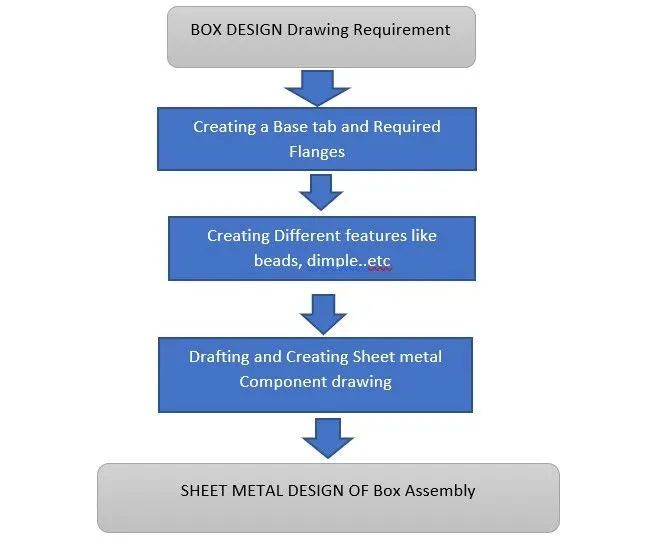
As shown in the Flow chart we will on different stages for the creation of the required sheet metal of Box Assembly and after the completion of the designing stage we will go for drafting phase and create the Flat pattern for drafting which will have the details of the bending of the component. In Nx there are so many tools which are used for making sheet metal designing workflow so easy but in this we will use a set of tools to create the final sheet metal model. Some of the used tools are listed below.
SHEET METAL TOOL FEATURES:
TAB: This tool is used to create a base tab with uniform thickness by create a sketch and adding with this is referred as base an we can create the other tab secondary for the different sheet metal design.
FLANGE: This tool is used to create a tab like attachments which makes it with the base tab and specifying bend radius and the length of the flange and required angles.
DIMPLE: This tool is used to crate a another layer accommodated with the bend radius on the tabs and flanges which is like stamping or will lift the surface by creating a sketch on the required surface of the required face of the tab.
BEAD: This tool is used to create a bead operation which is nothing but it will make a hollow flow operation nothing like a dimple creating only on the line of curve which will select .
UNBEND: This tool is used to unbend the flanges in to sheet metal operation sheet for layouts and this is doing by simply selecting the bend which we want to unbend.
REBEND: This tool is used to rebend the shape of the bend which is unbend and made in to flat shape after the operations like drawn cutout are other . The Nx will now the save the bend and again the shape of the bend is regained
CLOSED CORNER: This tool is used to create a closed two different bends and close them and making closed and having relief and different circular or oval and different corners.
THREE BEND CORNER: This tool is used to create a closed bend of three different bends and making closed and having relief and different corners.
FLAT PATTERN: This tool is used to create a flat pattern for drafting and sheet metal operations and for metal working purposes. We can create the flat pattern by considering the base tab surfaces.
DRAFT: This tool is used to create a draft for and make a document layouts of the required views and bends of the sheet metal we prepared in the sheet metal window.
BREAK CORNER: This tool is very necessary in the sheet metal operations to create a best cutting operation as it removes the pointed edges or corners of the sheet metal by making rounded corners by the specified radius.
HOLE: This tool is used to create different types of holes like screwed holes and of different size by selecting the features of the hole.
MIRROR BODY: This tool is used to create a Mirror of the selected body by taking the reference of the any plan as we specify.
HEM EDGE: This tool is used to create Hem edge by selecting the edge of the flange and giving the details of the loop and distance of the Hem.
NORMAL CUTOUT: This tool is used to create a cutout which is normal after creating a sketch we will select the curve for the required cut out.
DATUM PLANE: This tool is used to create a user specific plane in which we can draw sketch and use the plan for reference.
SKETCH TOOLS IN SHEET METAL:
LINE: This is tool feature which is used to create a line by specifying the coordinated and angles or by selecting the different points on the plane.
RECTANGLE: This is a tool feature which is used to create a rectangle with different ways by three point , or by corner method etc ..after that we can specify the dimensions.
POINT: This tool is used to create a point at the require distance or angle and highlighting it for the further drawings and features on the sheet metal.
CIRCLE: This tool is used to create the circle by consider the point by using the diameter and radius of the circle.
MIRROR FEATURE: This tool is used to create a mirror of the features by selecting the features and sketches of the feature . we have to make sure that we select the sketch of the feature to mirror.
STUDIO SPLINE: This is tool which used to create a spline by taking the reference of points and the tool will automatically create a curve and we have to select points it by clockwise or anticlockwise
MOVE CURVE: This tool is used to move the curve or shift the curve to distance and to rotate the curve by specifying the angle and distance by specifying a center point to move the curve.
PROCEDURE FOR CREATING THE BOX ASSEMBLY BY USING ABOVE LISTED TOOLS:
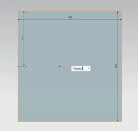
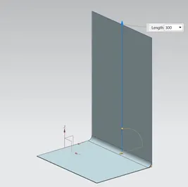
1. In this Modelling of the Box Assembly we will create atb of the dimensions as shown in the below figure . After that we create a two flanges of a distance of 300 mm as shown .
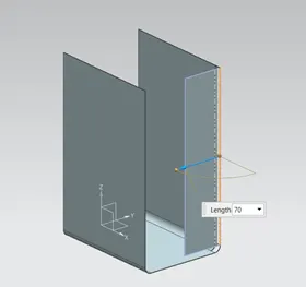
2.After that we create two another flanges each side of the created flange as shown in the figure. After we will use the Closed corner toll to create a closed edge by the selection of two different bends.
3. After that we will create a series of flanges and hem to create a close case structure as shown in the figure.in creating these flanges we will create a flange without any distance only having fillet radius 0.5 mm.
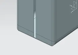
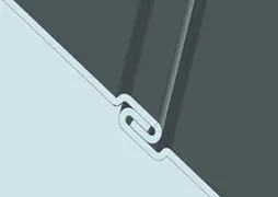
4.After create a mirror body by taking the reference of the YZ plane and a close body is created after that Unite the two bodies by using the Unite Body Tool.
5. After create a sketch and create a profile as shown in the figure by using the rectangle and move curve option to rotate and get the desired sketch . create a dimple form that Sketch with having a depth of 2 mm by selecting the material Outside option.
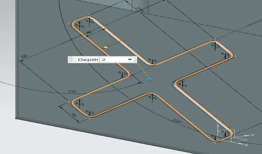
6. We will create a mirror feature by selecting the sketch of the profile along with dimple to create another dimple on the other side by taking the reference XZ plane.
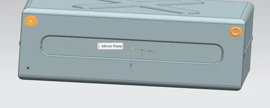
7.After that we will create another dimple at the bottom of the Box Assembly and making at depth of 2 mm by reversing the direction as such that the dimple is inside the box.
8.After that we will create a bead of circle profile of 1mm and create a mirror feature as how in the figure by selecting the respective to create another bead
9. After that we will create hem edges at all flange edges except one edge and after that we will create an datum and plane and create an another base tab at distance of 303 mm with a thickness of 3mm inside .
10. After that we will create a amother sketch and create a tab and break corner for 10 mm at one side . and create flanges at 40 degree angle of 14 mm and create another hem edge but change that to open loop the it will create a loop of radius 6 mm and 325 degrees.
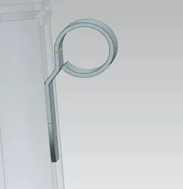
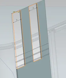
11.After that unbend and create a sketch to make a normal cut out as shown in the figure . Create mirror feature by selecting the ZX plane as reference plane.
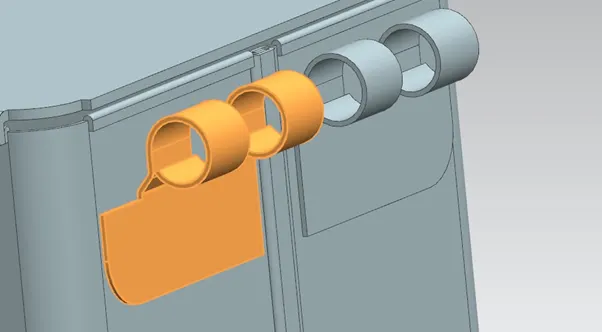
12. After that create another sketch as shown in the figure and create an another base tab .Create a flanges and make another hem edge of the same dimensions with a open loop and we can change until we get a perfect fit . after that unbend and create another cutout.
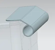
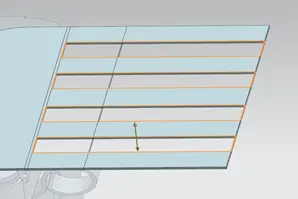
13.In this way after rebending the tab and cutout will take the place of empty places as shown in the above fiugures and a box Assembly will be created .
DIFFERENT VIEWS OF DESIGN:
SIDE VIEW:
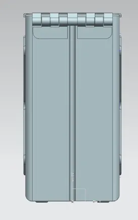
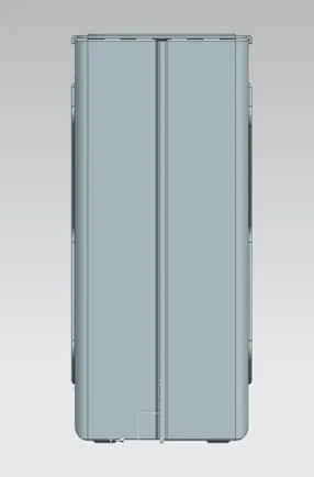
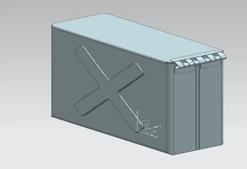
ISOMETRIC VIEW:
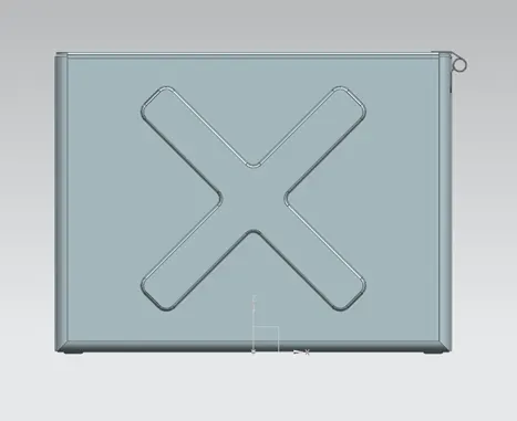
FRONT VIEW:
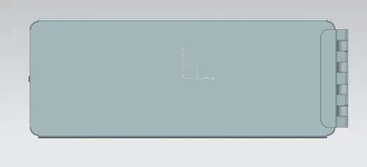
TOP VIEW:
CONCLUSION:
In this Box Assembly design we have made use of the different sheet metal tools and feature knowledge to create the desired modelling of Box for the sheet metal operation.