Advanced Sheet Metal Design Using NX Cad Challenge_2_Box Assembly
ADVANCED SHEET METAL DESIGN USING NX CAD - BOX ASSEMBLY
OBJECTIVE
The objective of this project is to create a box assembly in Siemens NX using the sheet metal tool and to create a draft of the sheet metal casing in NX.
INTRODUCTION
- Sheet metal is metal formed by an industrial process into thin, flat pieces. Sheet metal is one of the fundamental forms used in metalworking, and it can be cut and bent into a variety of shapes.
- Countless everyday objects are fabricated from sheet metal. Thicknesses can vary significantly. Sheet Metal application provides an environment for the design of sheet metal parts used in machinery, enclosures, brackets, and other parts normally manufactured with a brake press.
- Siemens NX sheet metal design software incorporates material and process information in sheet metal-specific modelling features: bends, flanges, tabs, cutouts, beads, dimples, louvres, corner and edge treatments, patterns, and other formable features.
- You can also quickly convert solid models to sheet metal components, and create sheet metal parts that enclose other components. More than 85% of Sheet metal industries use NX CAD as a design tool.
DESIGN METHODOLOGY
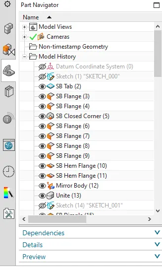
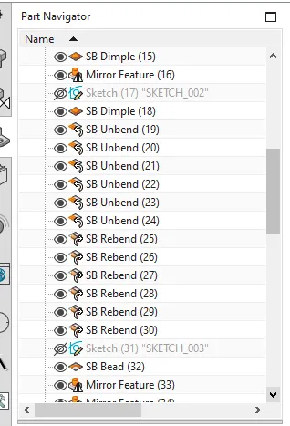
SHEET METAL BOX ASSEMBLY > TAB > FLANGE > CLOSED CORNER > HEM FLANGE > MIRROR BODY > UNITE > DIMPLE > MIRROR FEATURE > DIMPLE > UNBEND & REBEND > BEAD > MIRROR FEATURE > HEM FLANGE > TAB > FLANGE > TAB > BREAK CORNER > FLANGE > HEM FLANGE > UNBEND > NORMAL CUTOUT > REBEND > MIRROR BODY > TAB > BREAK CORNER > FLANGE > HEM FLANGE > UNBEND > NORMAL CUTOUT > REBEND > DRAFTING.
DESCRIPTION
Sketch - It is a basic and initial operation for creating any kind of sheet metal components.
Tab - It is a base feature that forms by extruding the sketch along a vector by providing thickness or adds material to a plane face.
Normal cutout - It cuts the material perpendicular to the sketch.
Bend - It is used for bending the material on one side of a sketch line by adding a bend between two sides.
Flange - It adds a flat flange on basis of edges at an angle to a planar face and adds bend between them.
Break corner - It Rounds a sharp corner at edges. It avoids sharp edges by making it smooth.
Closed corner - It Creates or closes the corner of sheet.
Unbend - It flattens a bend and material adjacent to the bend.
Mirror - It is used to create same features or sketches on basis of plane or sketch.
Mirror body - It mirrors the body w.r.t reference plane.
Datum plane - A new plane is created w.r.t reference Datum.
Unite - It combines two or more bodies into a single body.
Hole - It creates a whole on basis of circle created.
Dimple - It lifts an area along the contour of a sketch that forms an stamping tool.
Bead - It lifts a material along the contour of a sketch that forms an stamping tool.
Rebend - It restores a bend.
Drafting - It is used to draw 2D drawing from a 3D model. The drawing shows dimensions, relations, annotations etc. which is used to manufacture the components.
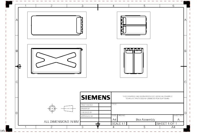
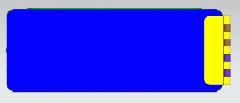
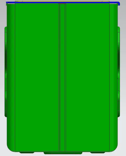
IMAGES OF BOX ASSEMBLY
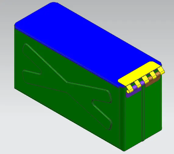
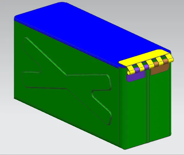
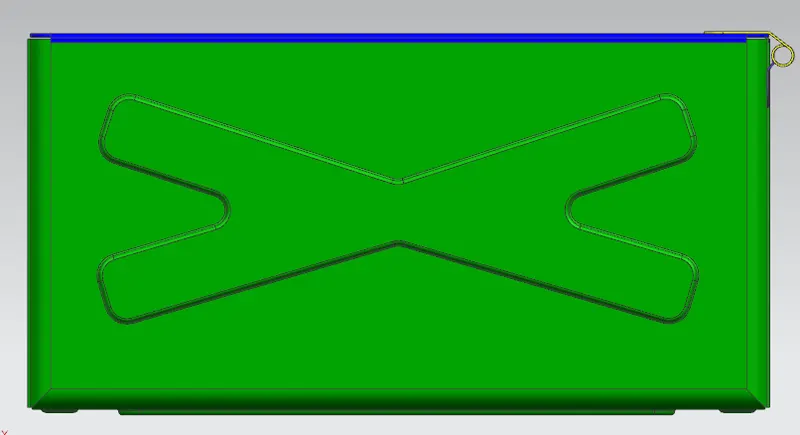
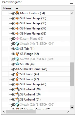
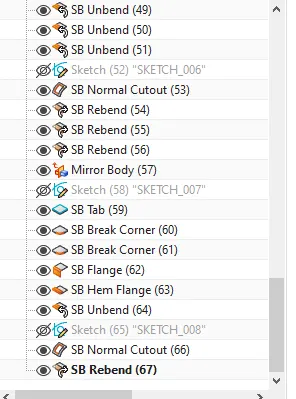
IMAGES OF FEATURE TREE
CONCLUSION
Thus, creating a box assembly is done using sheet metal tools in Siemens NX by understanding the user interface with NX cad.