Advanced Sheet Metal Design Using NX Cad Challenge_1_Casing Design
Sheetmetal Casing Design
using Siemens NX
Objective:
The objective of this project is to create a detailed and accurate 3D model of a sheet metal casing using Siemens NX Sheetmetal application. The model will include various features such as bends, flanges, cutouts, holes, and dimples. The primary goal is to showcase the capabilities of the Sheetmetal tools in Siemens NX and demonstrate a systematic design methodology.
Introduction:
Sheet metal components are widely used in various industries for their lightweight, durable, and cost-effective nature. The Siemens NX Sheetmetal application provides specialized tools for designing and modeling sheet metal parts, ensuring precision and efficiency in the design process.
Design Methodology / Approach:
Sketching:
Begin by creating 2D sketches representing the base shape of the sheet metal casing.
Changing design parameters:
Adjust design parameters such as thickness, material, and overall dimensions as needed.
Adding solid sheet and cutouts:
Apply a solid sheet to the sketch and add cutouts using appropriate commands.
Adding lines and bending at the appropriate angle:
Use the bending tool to introduce bends at specified angles, creating the 3D form.
Adding flanges:
Incorporate flanges to enhance structural rigidity and provide mounting surfaces.
Breaking corners to round off sharp edges:
Apply fillets or rounds to break sharp corners, improving aesthetics and safety.
Unbending the metal sheet:
Utilize the unbending feature to view and modify the flat pattern of the sheet metal.
Creating points to position holes and adding holes:
Define points for hole locations and use hole creation tools to add perforations.
Creating a sketch and adding dimples:
Create sketches to specify dimple locations and use the dimpling tool for added detail.
Rebending:
After adding features like holes and dimples, rebend the sheet to see the final 3D form.
Drafting:
Generate 2D drawings with necessary annotations, dimensions, and other details.
Description (Features Used in Modeling):
Sketching Tools: Used for creating 2D profiles that serve as the basis for sheet metal design.
Design Parameters: Adjusted to meet specific requirements regarding thickness, material, and dimensions.
Bending Tools: Applied to introduce bends in the sheet metal, forming the desired 3D shape.
Flange Tools: Used to add flanges for structural support and mounting surfaces.
Fillet/Rounding: Applied to break sharp edges, improving aesthetics and safety.
Unbending Feature: Used to visualize and modify the flat pattern of the sheet metal.
Hole Creation Tools: Utilized to add perforations in the sheet metal at defined locations.
Dimpling Tool: Applied to create dimples for added design detail.
Rebending: Used to restore the 3D form after adding features like holes and dimples.
Drafting: Employed for creating detailed 2D drawings with annotations.
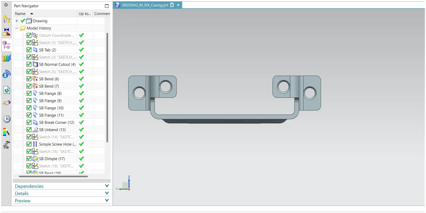
Screenshots of the Model:
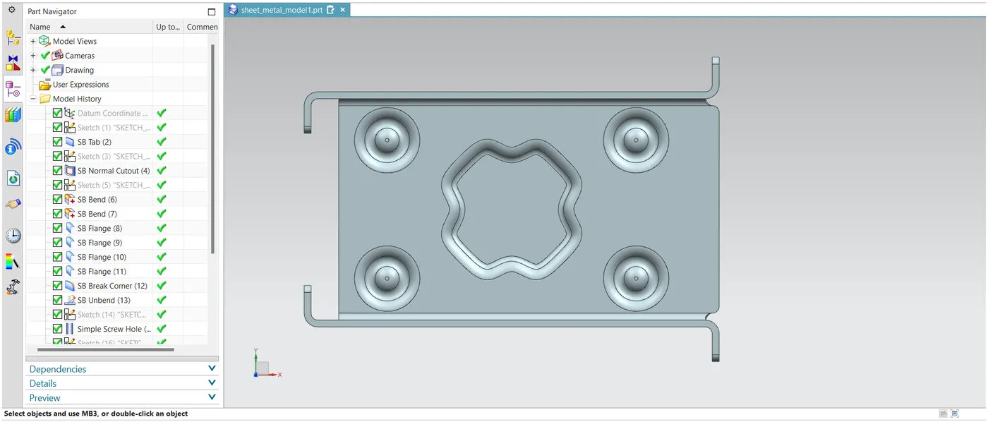
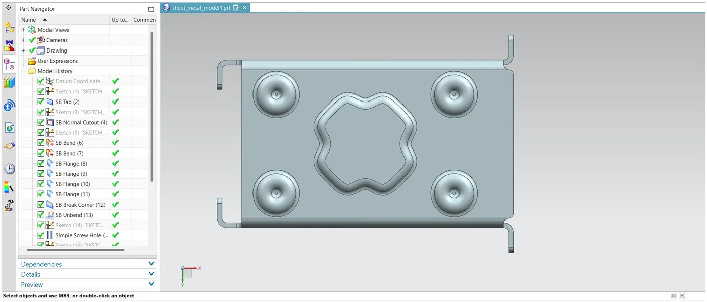
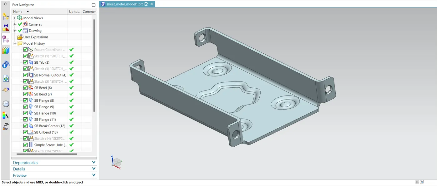
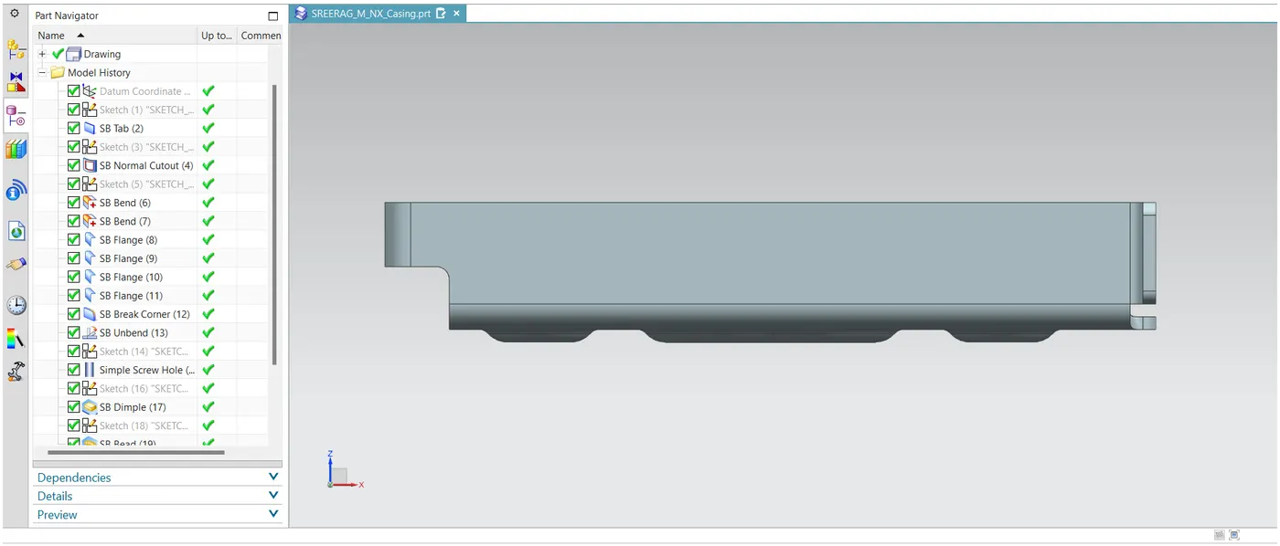
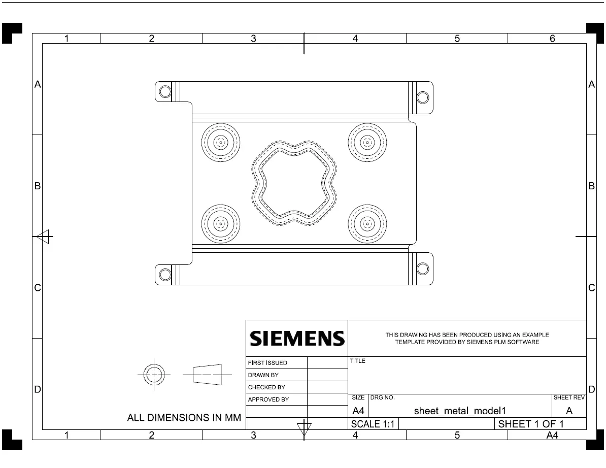
Detailed Drawing Sheet Image:
Conclusion:
In conclusion, the Siemens NX Sheetmetal application provides a comprehensive set of tools for designing intricate sheet metal components. The systematic design methodology employed in this project ensures accurate modeling and showcases the diverse features available in the software. The resulting sheet metal casing demonstrates the capabilities of Siemens NX Sheetmetal in creating detailed and manufacturable sheet metal parts.