Advanced Sheet Metal Design Using NX Cad Challenge_1_Casing Design
Casing Design Using NX CAD
Objective:
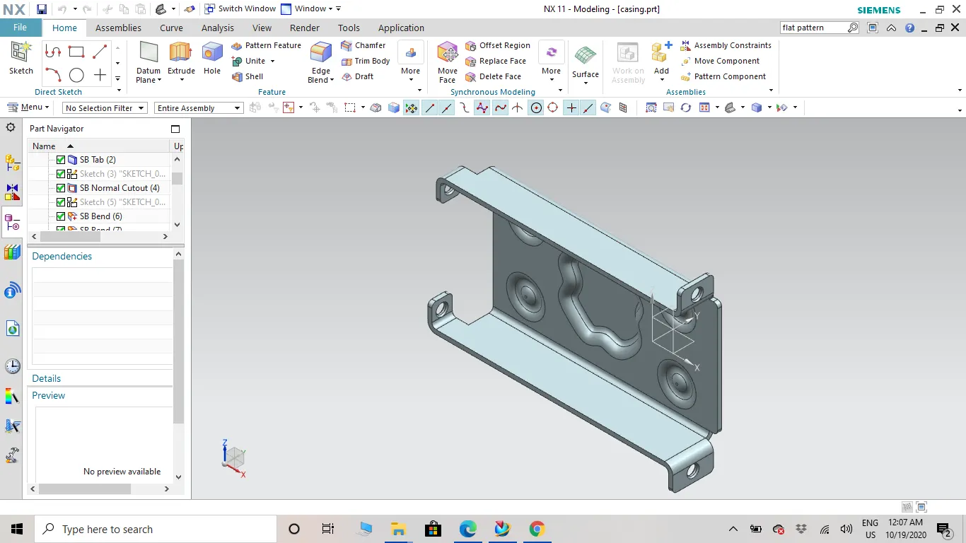
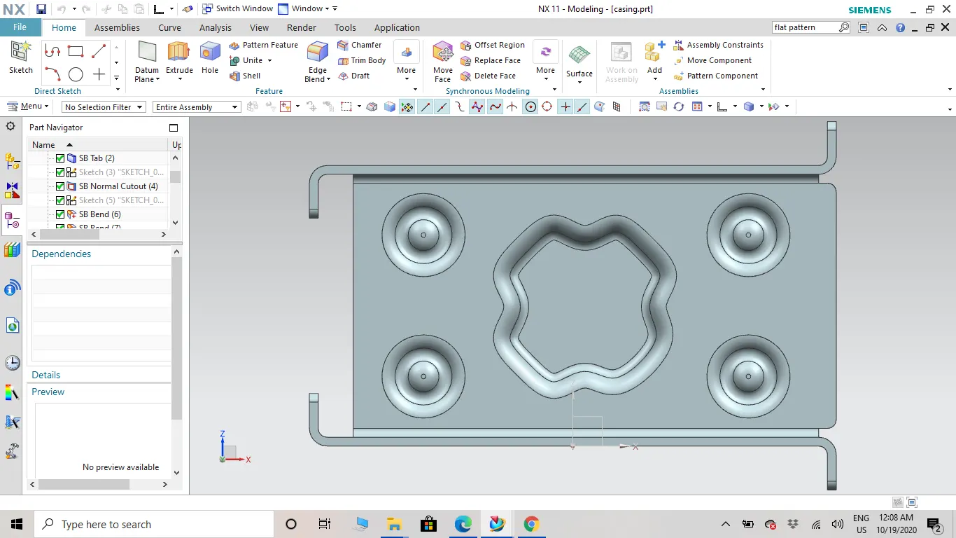
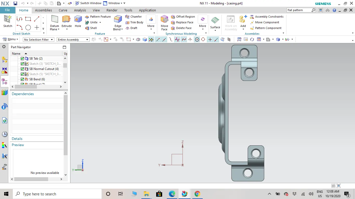
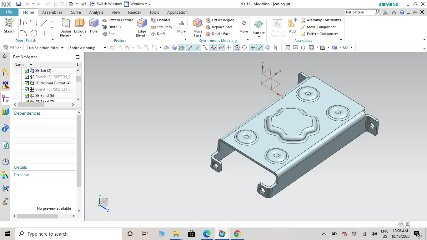
The obejective of this assignment is to learn how to apply sheet metal commands step by step to design casing in NX CAD.
Introduction:
Casing Design is used in many automobile industries while manufacturing the body of an automobile & applications varies according to the design of the body while cosidering aesthetics of an automobile & NX CAD is a modelling software used for modelling of the Casing.
Design Methodology:
1. select the application where it is utilized and calculate the dimensions
2. consider the volume it occupies and consider the other parts where it is to be assembled.
3. Design the dimensions accordingly and create 2d & 3d models using design softwares.
4. Analyse the loads & forces on it and find out the Factor of Safety of the product and recommend changes if needed.
This is the design methodology applied for any components.
Approach in NX CAD.
KEY COMMANDS : Rectangle,tab, Normal cut out,bend, flange,breaking corners, rebend, holes,dimple, bead,drafting(flat sketch) & views.
Step 1: Open NX CAD-sheet metal & sketch.
Step 2: Draw a Rectangle with (60 *50) as dimensions
Step 3: Set Sheet metal preferences(Metal thickness, bend radius, Relief depth, relief width-1mm (these are the parameters which are needed to be set as prefereneces and value changes as per applications).
Step 4: Add tab cammand to the rectangular profile & draw a rectangle on face with dimension (5 *40) and apply normal cut to the profile.
Step 5: Draw a line sketch and exit the sketch and apply the bend command.(set parameters such as curve, face angle (90) and apply them).
Step 6:Add flanges at the corners (set parameters such as (width option, length, angle, length preference, and option such as face, length inset).
Step 7:Add flanges and apply break corner command to all the flanges with required parameters such as face, method, breaking corners).
Step 8: Rebend the edges and apply hole command by drawing holes with required parameters hole type, clearance limit.
Step 9 : Draw a sketch at the axis point and apply stdio spline command to modify the sketch in required spline (in stdio spline set parameters such as type - field to poles, degree-3, movemet- view,parametrisation-closed,).
Step 10.Apply move curve option set parameters such as filed to angle and choose 45 degrees.
Step 11:Select dimple option & set all parameters(Depth-1mm. depth angle-0, depth reference-inside, side walls-materials inside) set rounding parameters to 1mm, set minimum clearance tool-5mm).
Step 12: Draw circles with 5mm diameter mirror them to 4 nos and apply bead withset parameters to 1mm.
Step 13; and bend them in the same pattern in which you applied rebend.
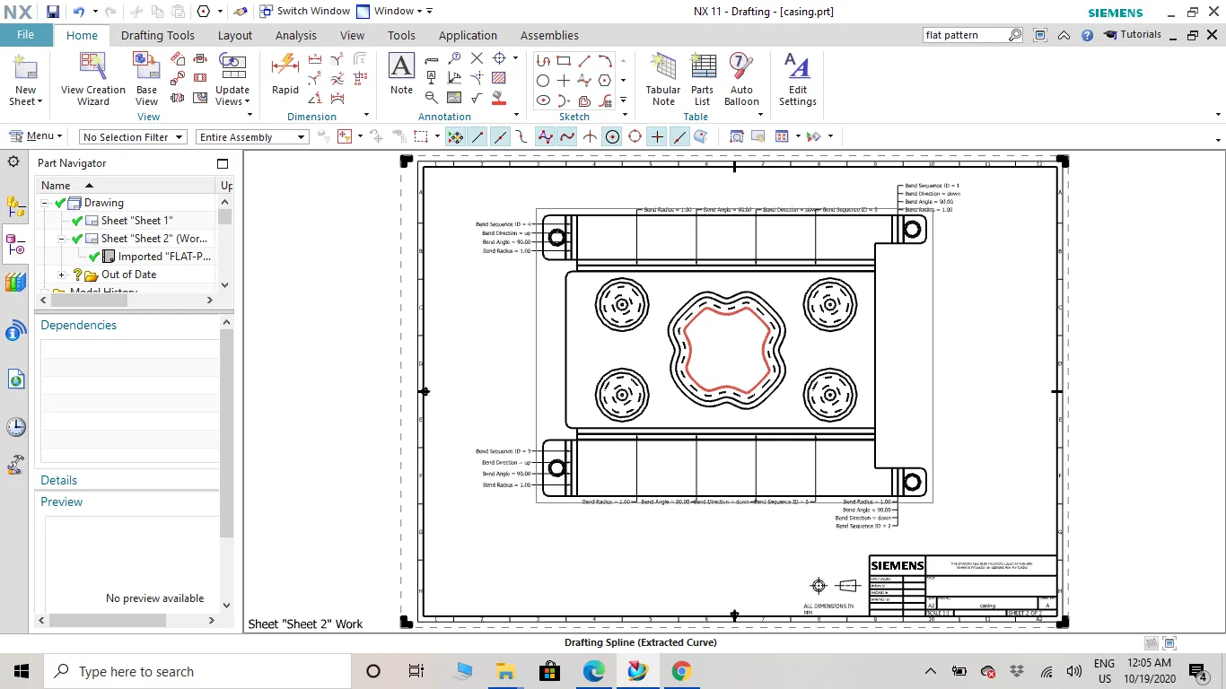
Drafting;
Step 1: create flat pattern option and make it visible in the part navigator
Step 2 : go to application select - drafting
Step 3: Add base view applying flat pattern view.
& save the part
Conclusion: Sheet metal design has lot of applications while creating the automobile bodies such as cars, ship building,& aeroplane bodies, so for manufacturing precise bodies.