Advanced Sheet Metal Design Using NX Cad Challenge_1_Casing Design
Title of the project: Advanced Sheet Metal using NX cad Challenge 1 Casing Design.
Objective: To design a Sheet metal Casing Design using Siemens NX Sheet metal Application.
Introduction:
1. Sheet metal: It is formed by an industrial process into thin, flat pieces, It is one of the fundamental forms used in metalworking and it can be cut and bent into a variety of shapes. 2. NX: It is formerly known as “Unigraphics” and is an advanced high-end CAD/CAM/CAE, which has been owned by Siemens PLM Software. Mostly it is used for Design, Engineering analysis, manufacturing.
Design methodology:
Design methodology can be explained by the following flow chart.
Description:
Step1: A sketch was created in the XY plane(P) a rectangle was of dimension 60X50 mm and then using the TAB button rectangular metal sheet of 1mm thickness was created.Step2: a rectangular sketch of dimension 5X40 mm was created at the left edge of rectangular sheet metal and that part was removed using the feature Normal Cutout.
Step3: In-plane P a horizontal line was drawn at a distance of 10mm from the upper left end corner of the metal sheet. By using the bend feature, the metal sheet was bent at an angle of 90 degrees. And the same process was repeated for a line drawn at a distance of 10mm from the lower left end of the sheet.
Step 4: flanges of length 5mm were added at all joint portions of bent sheet metal by using the feature flange and make the fillet of radius the flange corner edges of radius 1mm using the feature Break corner.
Step 5: The required portions were unbent for adding some punch features by using the feature called Unbend by selecting the larger horizontal sheet metal as the stationary face.
Step 6: For adding holes to the sheet metal, four circles were drawn which were symmetric about the origin and then holes were created by using the feature Hole of clearance hole with M2 Screw size and an H13 fit.
Step 7: In P plane i.e., XY plane requires sketch, where each half side is 5mm in length with centered at (0,0,0) and by using the studio spline, the required finished sketch was drawn at an angle of 45 Degrees. For the drawn sketch dimple was created by using the feature Dimple of depth 1mm.
Step 8: In-Plane P a circle of diameter 5mm was drawn and by using the Bead feature required feature was created of depth 1mm.
Step 9: By using the Mirror feature create other beads on four corners along with the Dimple feature.
Step 10: The bent portions were rebent using the feature Rebend and finally the required casing was made.
Different Views of the model:
1)Front View:-
2)Side View:-
3)Top View:-
4)Isometric View:-
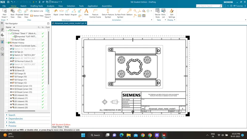
Drawing Sheet:
Conclusion: By this, I have learned how to use simple features like Tab, flange, break corner, dimple, bead, bend and unbend.