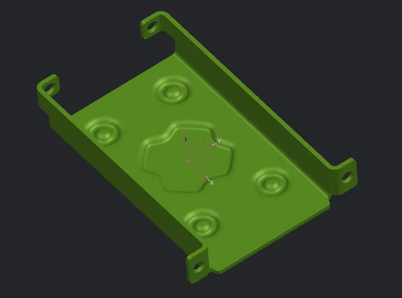
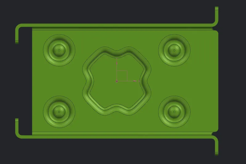
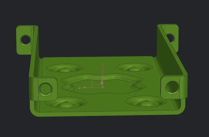
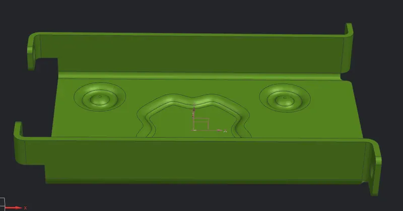
Advanced Sheet Metal Design Using NX Cad Challenge_1_Casing Design
NX-Casing
Aim:
To create Sheet Metal Component with Sheet Metal modelling tools applied throughout the modelling using NX.
Introduction:
In this we are going to create sheet metal casing step by step using seimens NX sheetmetal applicatiion.
Design methodology:
Tab -> Normal cutout -> Bend -> Flange -> Break corner -> Unbend -> Hole -> Dimple -> Bead -> Rebend -> Flat pattern.
Procedure:
Step 1: Tab
- Start Nx and create new file then the first step is to draw a sketch rectangle of length 60mm and width 50mm and exit sketch.
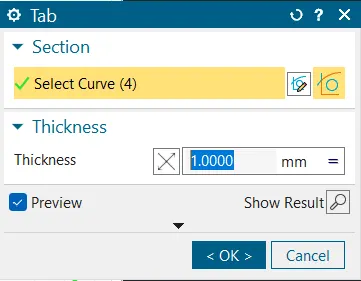
- Edit design parameter Menu -> parameters -> sheetmetal change the global value to 1mm and click ok.
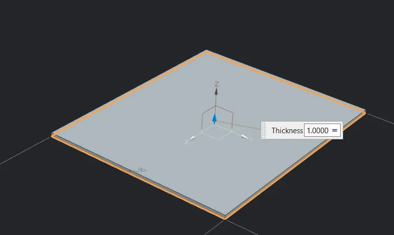
- Then click tab button
 button for creating first sheet metal model.
Step 2: Normal cutout
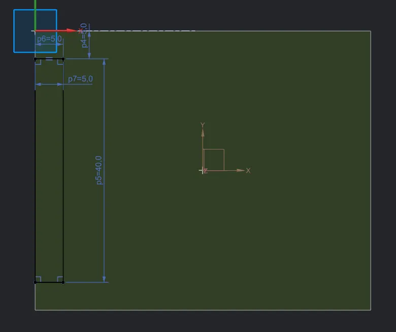
- Sketch a rectangle symmetric w.r.t to x-axis which coincident with the left edge of tab for the width of 5mm and length of 40mm.
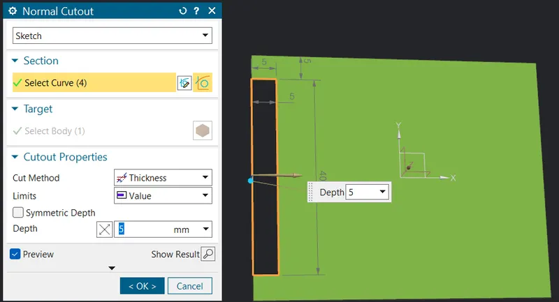
- Exit the sketch mode and use the cutout button
 for making a rectangular hole in the tab.
Step 3: Bend
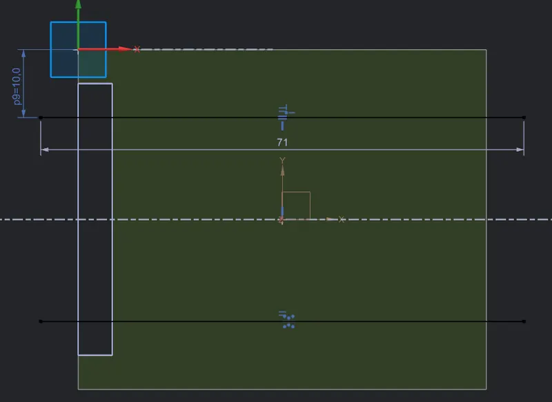
- Sketch two symmetric lines on the face of tab w.r.t to x-axis and the upper line is 10mm from the upper left corner.
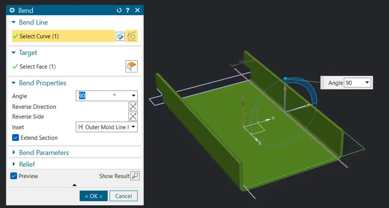
- Exit sketch the click bend button
 give the angle as 90° by selecting the first line and repeat the same for the other symmetric line (reverse the direction for this line) .
Step 4: Flange
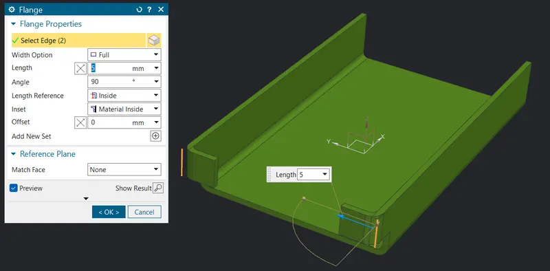
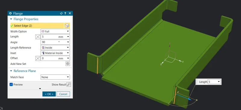
- Click the flange button
 use the length as 5mm and select the outside edge as shown apply the same on the other side of the tab to obtain the final result as shown.
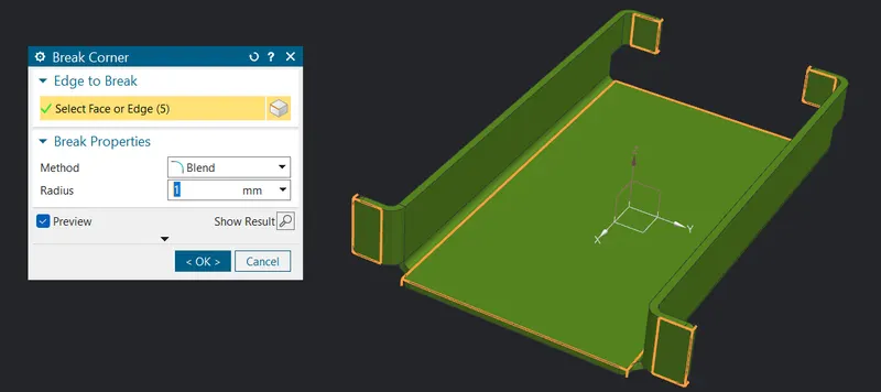
Step 5: Break corner
- Click on the break corner button
 and give the blend radius as 1mm the select the edge or face to apply.
Step 6: Unbend
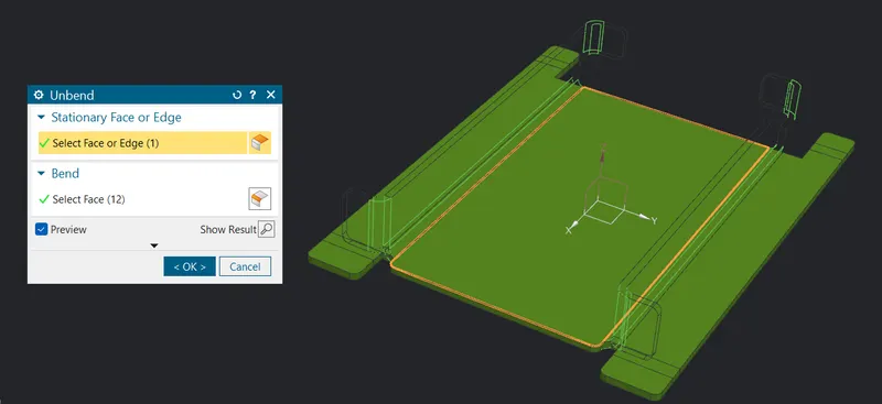
- Select the unbend button
 then give the stationary face as middle one and select the rest as bend.
Step 7: Hole
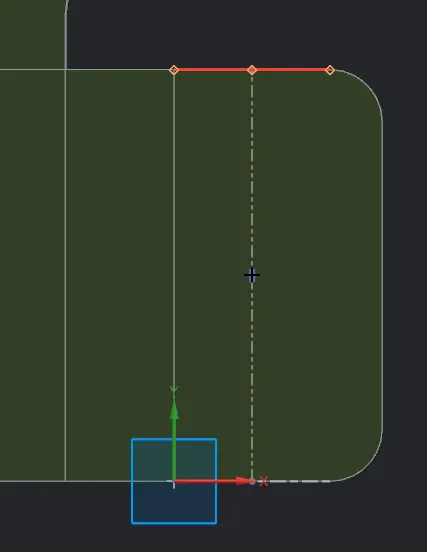
- At first we need four points to create a hole.
- Sketch a line at the flange by using the middle points of edge and then create a point at the center of line.
- Similarly draw them on the other flange symmetric to the previous one and create a point.
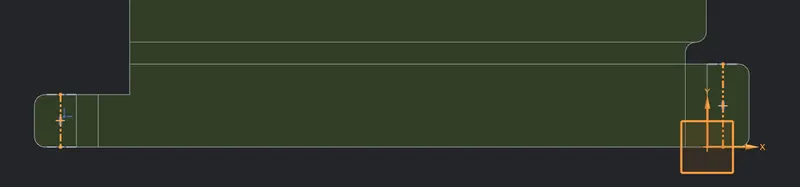
- Then mirror the two points using mirror curve and x-axis as center line as shown.
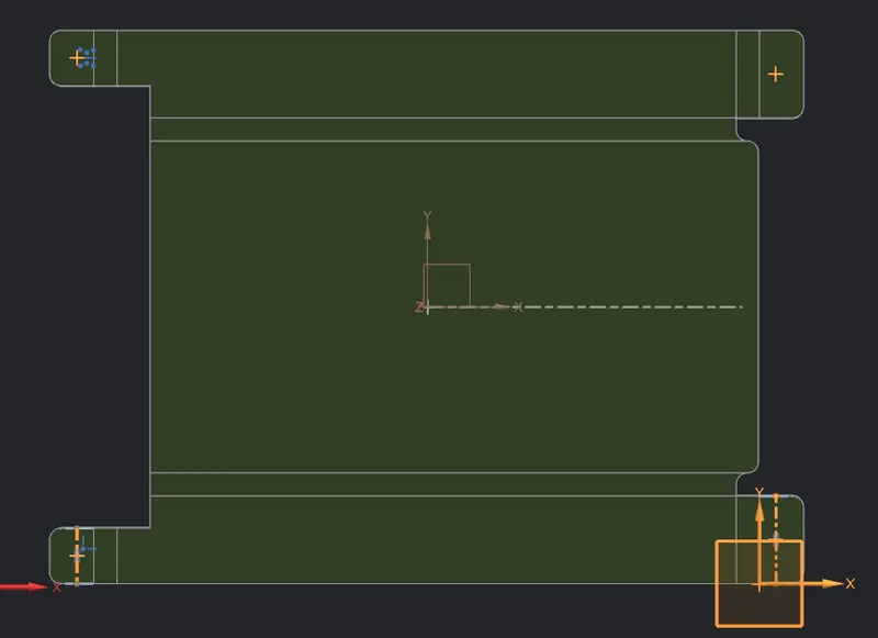
- Select the Hole button
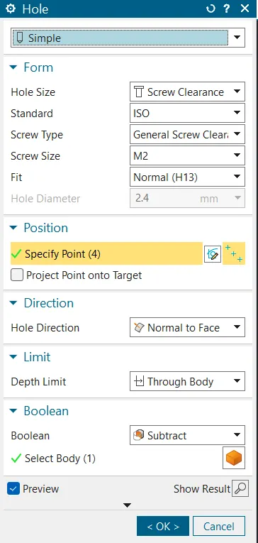
 if you can't find the button use command finder and select them.
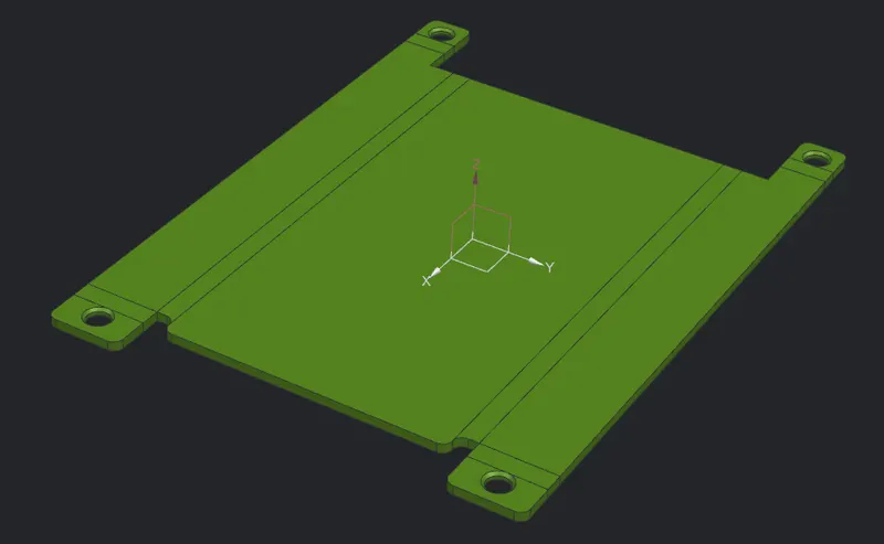
 - And then give the parameters as shown and select the four points.
Step 8: Dimple
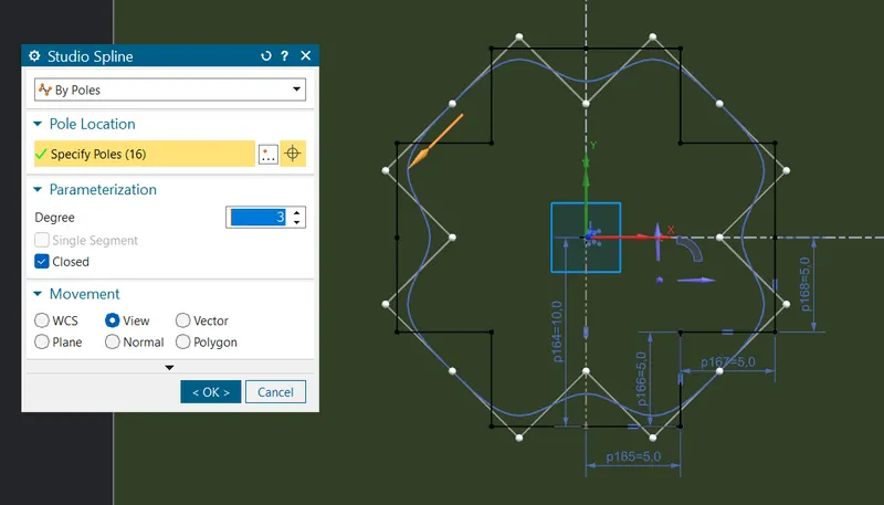
- In the XY-plane create the following cross sketch where each side is 5mm length, the sketch is centered at the origin.
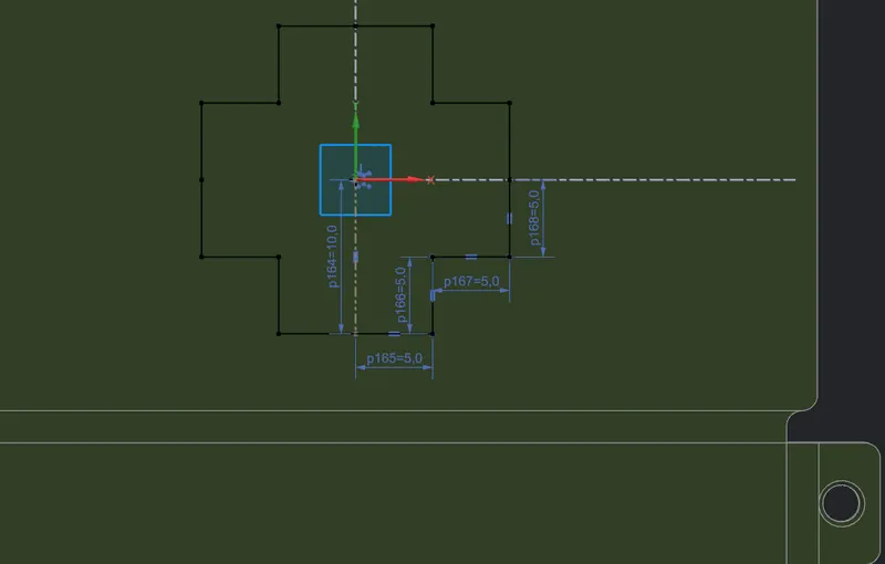
- Click on the spline and select the By poles option as well tick the closed option in dialog box.
- Select one by all the 16 points of the sketch in clockwise direction and click ok.
- Use move curve and select the angle give the value as 45° and final results as shown.
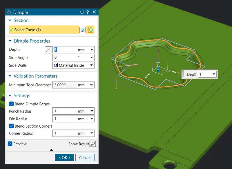
- Select the dimple button
 and give the value as shown.
Step 9: Beads
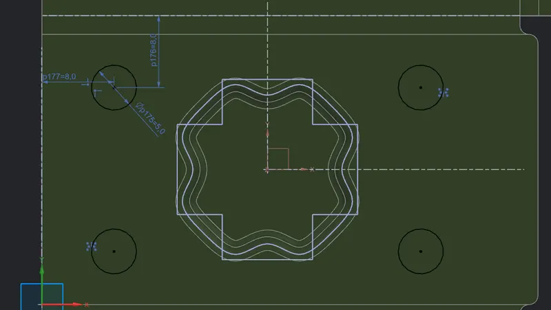
- In XY plane draw circle of 5mm as shown and mirror them using x-axis and y-axis as circular line.
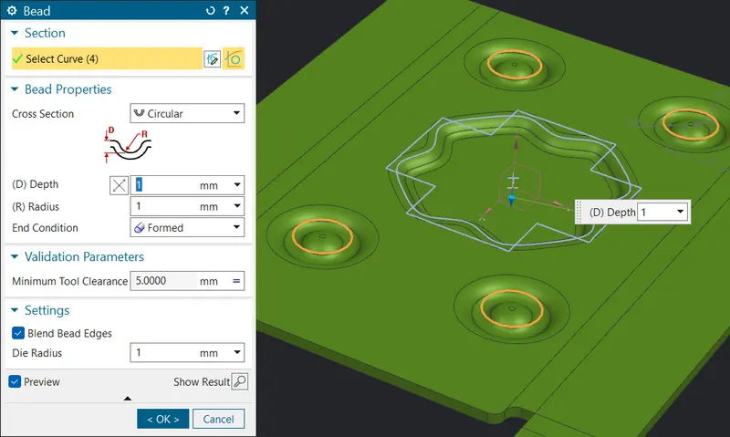
- Click on the bead button from the more option in punch then give the value as shown.
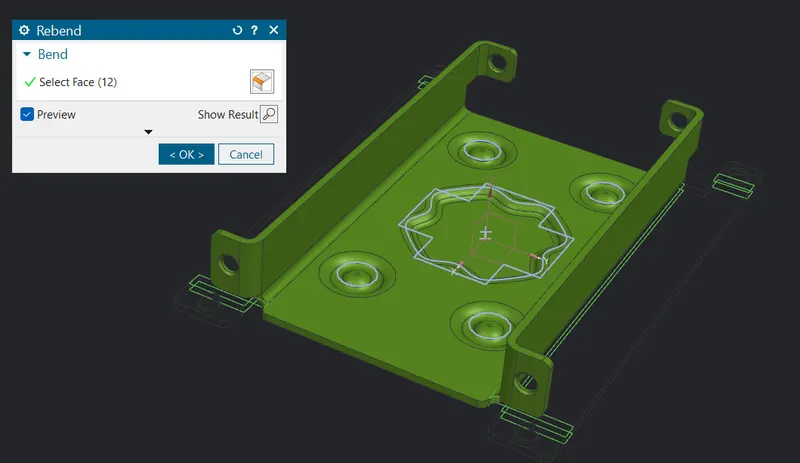
Step 10: Rebend
- Rebend the faces by selecting them in reverse order in which they were bend as shown.
Step 11: Flat pattern
- Select the flat pattern button
 and select the central face.
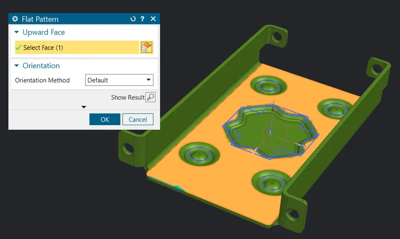
- For the moment the flat pattern will not be visible in part navigator go for the flat pattern view so you can see them.
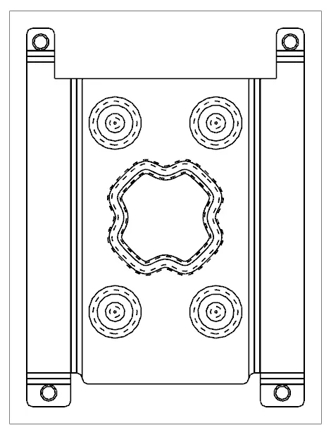
Result: Drafting
- Go for drafting ctrl + shift + D as shortcut a window will pop-up then give paper size and select the flat pattern as view in base view as well as go for 2:1 scale ratio for bigger size.
- Then delete the unwanted text generated along with it you can also give further dimensions and print them if need.
Model: