Advanced Sheet Metal Design Using NX Cad Challenge_1_Casing Design
CASING DESIGN
AIM:
- To design casing in Siemens NX sheet metal as per given instructions
Sheet metal operations:
Bending
Bending is a process whereby a force is applied to sheet metal which causes it to bend at an angle and form the desired shape. Bends can be short or long depending on
what the design requires.
Bending is performed by a press brake machine that can be automatically or manually loaded. Press brakes are available in a variety of different sizes and lengths (20-200 tons) depending on the process requirements.
Bend line– The straight line on the surface of the sheet, on either side of the bend, that defines he end of the level flange and the start of the bend.
Bend radius – The distance from the bend axis to the inside surface of the material, between the bend lines.
Bend angle – The angle of the bend, measured between the bent flange and its original position, or as the included angle between perpendicular lines drawn from the bend lines.Sometimes specified as the inside bend radius. The outside bend radius is equal to the inside bend radius plus the sheet thickness.
Neutral axis – The location in the sheet that is neither stretched nor compressed, and therefore remains at a constant length.
K-factor – The location of the neutral axis in the material, calculated as the ratio of the distance of the neutral axis T, to the material thickness t. The K-factor is dependent upon several factors (material, bending operation, bend angle, etc.) and is greater than 0.25, but cannot exceed 0.50. K factor = T/t
Bend allowance – The length of the neutral axis between the bend lines or the arc length of the bend. The bend allowance added to the flange lengths is equal to the total flat length.
K-Factor
The K-factor is the ratio between the the neutral axis to the thickness of the material.
Importance of the K-factor in sheet metal design
The K-factor is used to calculate flat patterns because it is related to how much material is stretched during bending. Therefore it is important to have the value correct in CAD software. The value of the K-factor should range between 0 – 0,5. To be more exact the K-factor can be calculated taking the average of 3 samples from bent parts and plugging the measurements of bend allowance, bend angle, material thickness and inner radius into the following formula:
| Tolerances | |
|---|---|
|
Forming and Bending:
|
+/- 0,4 mm
|
|
Bend to hole or feature:
|
+/- 0,2 mm
|
|
Linear dimensions excluding locations to bends
|
+/- 0,1 mm
|
|
Diameters with inserts
|
+/- 0,06 mm
|
|
Angularity
|
+/- 2 degrees
|
|
Surface roughness
|
+/- 3,2 micrometers
|
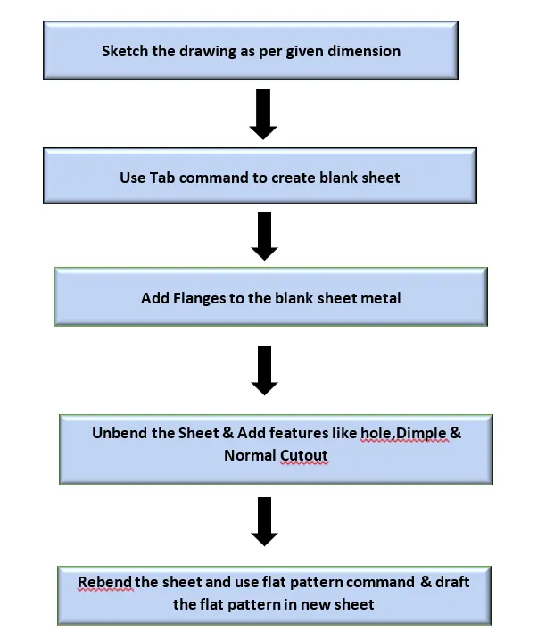
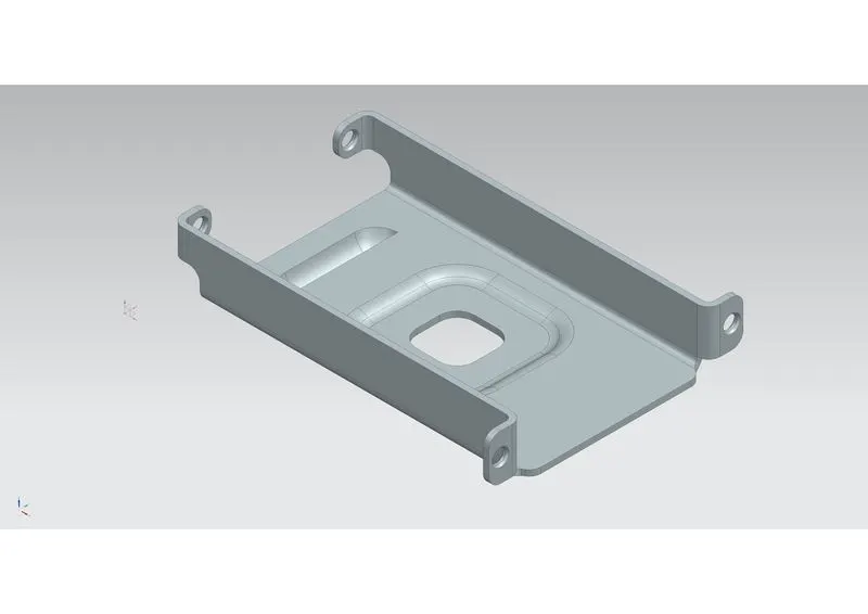
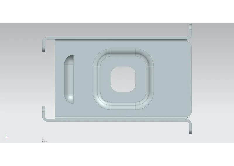
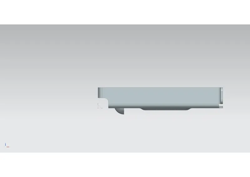
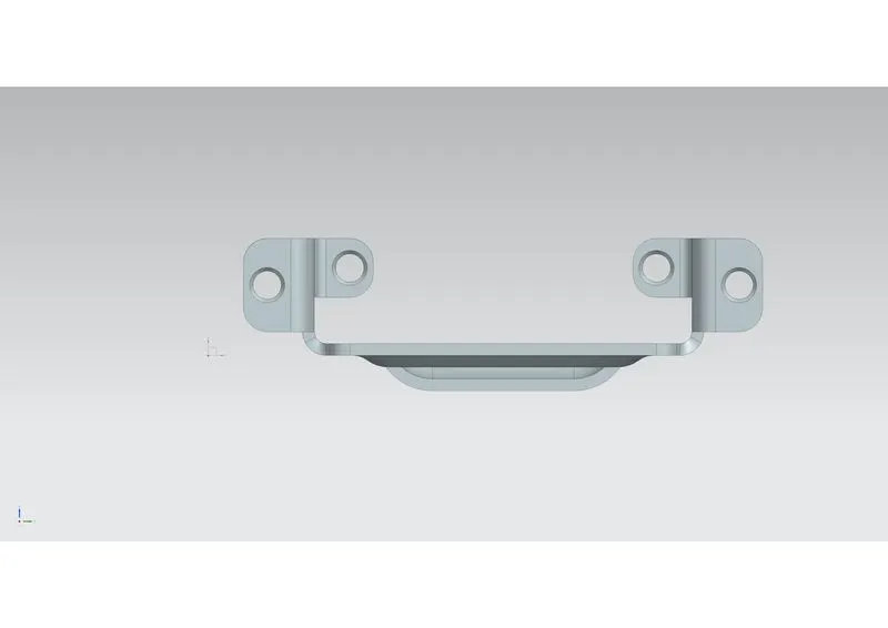
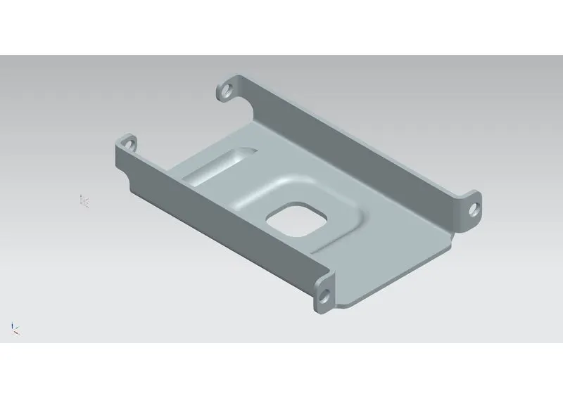
- Tab - Tab is a command used to create a base for any sheet metal part that can be extruded from a sketch. The sketching plane can be selected as per the designer’s choice.
- Flange - It is used to create an extended part (bend) of a sheet metal. It is created at the edge of one side of the model. This command will allow us to select the edge of the base to create a projecting flat extruded surface. The angle, width, length, and type of flange can be determined as per the requirements.
- Unbend - This feature is used to unbend the adjacent bends and flatten them. Here it is used to create more features. This command is used to unbend the sheet metal parts to create geometries and work on complicated designs. In this command, we have to select a stationary face and then select the corners of flanges to unbend.
- Rebend - It is used to rebend the corners that were bent before along with any features added after the unbend feature.
- Bead - It lifts material along the contour of a sketch that simulates a stamping tool, it is used for giving strength to the sheet metal. Here two beads are created on the unbent surface. The selected sketch is lifted off from the base to provide strength to the material. Similar to dimple, the material can be removed in both directions.
- Hole - It adds a hole to one or more solid bodies in a part or an asembly with options for counterbored, countersunk and threaded. Here six simple holes are created on the unbent surface with a diameter of 10mm. It can be used to make customized or standardized holes along with a defined point or path. The dept of the hole can be controlled.
- Flat pattern - It creates a flat pattern feature from the formed sheet metal part. The user chooses this command to create a flat view of the sheet metal after unbending all the sides and faces. This view can be used in drawing the flat pattern along with the bend radius and other dimensions.
- The sheet metal is designed as per given instructions.