Advanced Sheet Metal Design Using NX Cad Challenge_1_Casing Design
Objective:
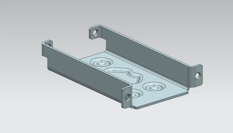
- To design a Sheet metal Casing Design using Siemens NX Sheet metal Application.
Introduction:
- Sheet metal: It is formed by an industrial process into thin, flat pieces, It is one of the fundamental forms used in metalworking and it can be cut and bent into a variety of shapes.
- NX: It is formerly known as “Unigraphics” and is an advanced high-end CAD/CAM/CAE, which has been owned by Siemens PLM Software. Mainly it is used for Design, Engineering analysis, and manufacturing.
Design methodology:
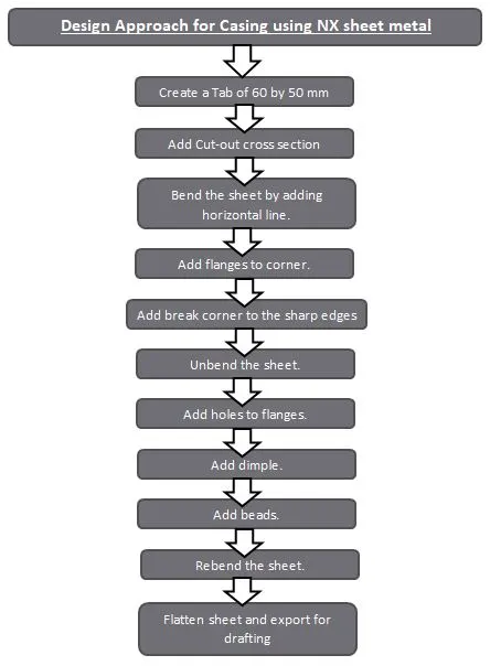
- The following flow chart can explain the design methodology.
Description:
Sketch:
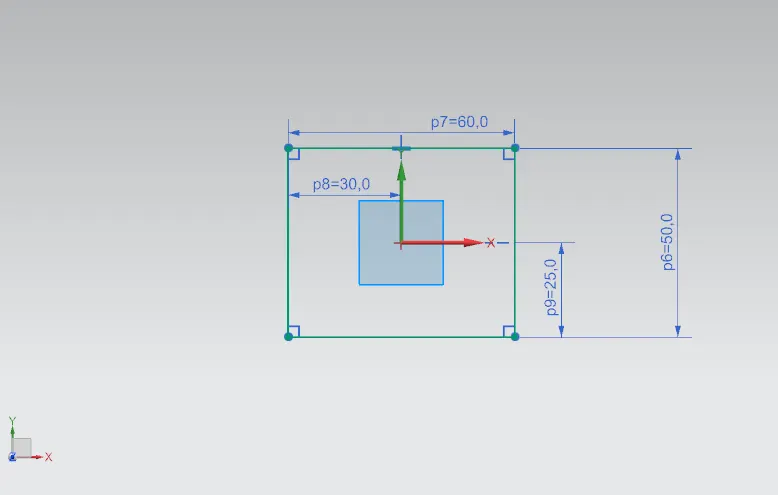
- This is the very basic element in any feature of the design of sheet metal components. This is the first step for the creation of a tab; therefore, it is called a base sketch. In this project, a rectangle of the required size was drawn on the XY plane.
Tab:
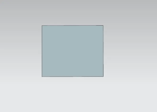
- Before tab creation, parameters and characteristics for sheet metal commands were set with the required material thickness, bend radius, relief width and depth. The tab is a feature that creates a base feature by extruding a sketch along a vector by a thickness value or adding material to a planar face. After this, A sketch was drawn on the XY plane making the normal cut-out at one side of the tab.
Bending:
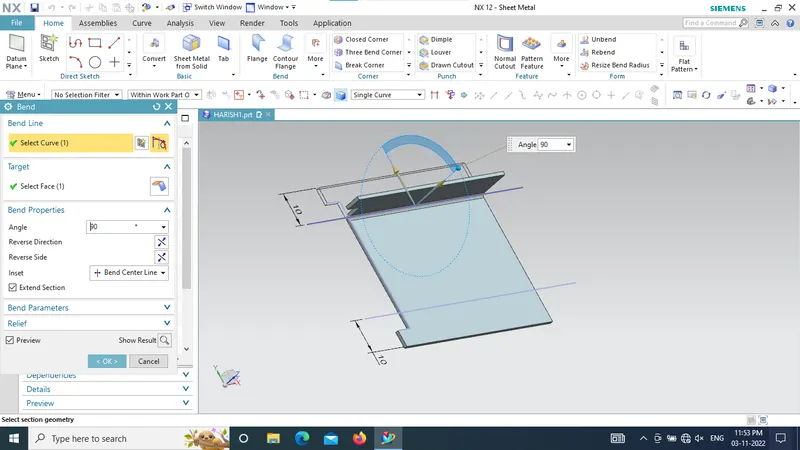
- This feature modifies the model by bending material on one side of the sketch line, adding a bend between the two sides. A sketch consisting of two horizontal lines was drawn on the face of the tab to bend.
Flanges:
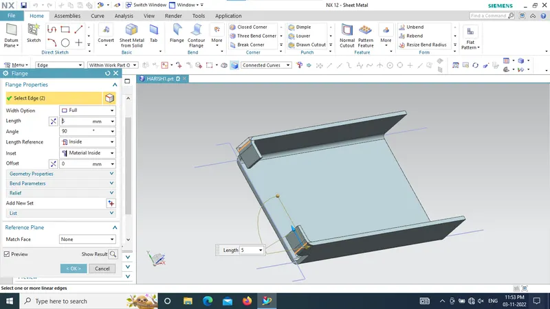
- This feature adds a flat flange at an angle to a planar face and adds a bend between the two. Two flanges facing each other were created and another two flanges facing apart were created.
Break Corner:
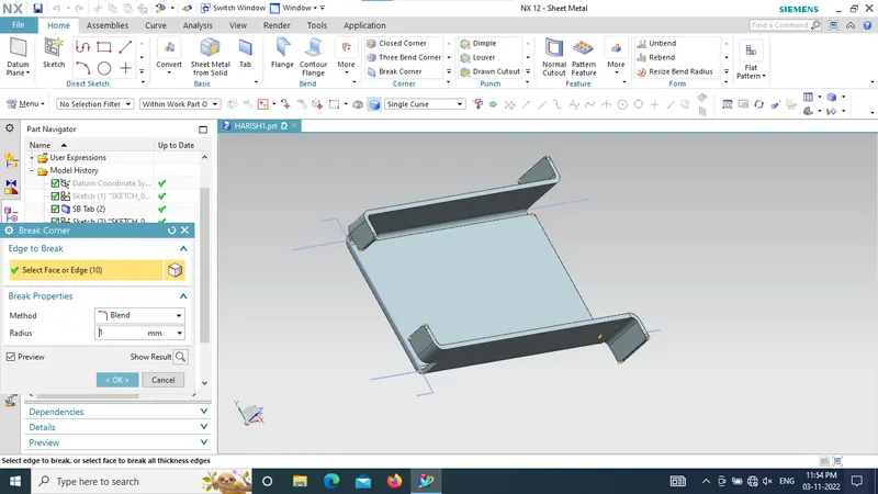
- This is a feature, which rounds or chamfers a sharp corner of a tab or flange. This feature is similar to the fillet feature in some other CAD software. To avoid the stress concentration at the edges, break corners were provided.
Unbend:
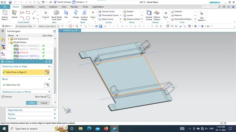
- It is a very useful feature in Siemens NX software. It flattens a bend and the material adjacent to the bend. To achieve the flat configuration of the sheet metal as per the design intent, have to choose the bend in an order. Inbox selection of bend is also possible. Most of the advanced features of the NX sheet metal are only applied after the unbent state.
Holes:
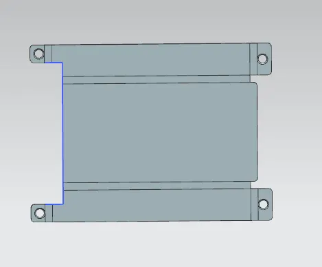
- This feature adds a hole to one or more solid bodies in a part or assembly with options for counterbored, countersunk and threaded. In this project, at four ends of the unbent flanges, points for holes were drawn with the help of points and lines and these points be symmetrical to X-axis.
Dimple:
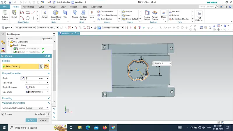
- This is a feature in the NX Sheet metal application which gives structural rigidity to the sheet metal part. This feature lifts an area of the model inside a sketch that simulates a stamping tool. In this project, a sketch consisting of 16 points and a spline was drawn to create the dimple on the unbent blank.
Beads:
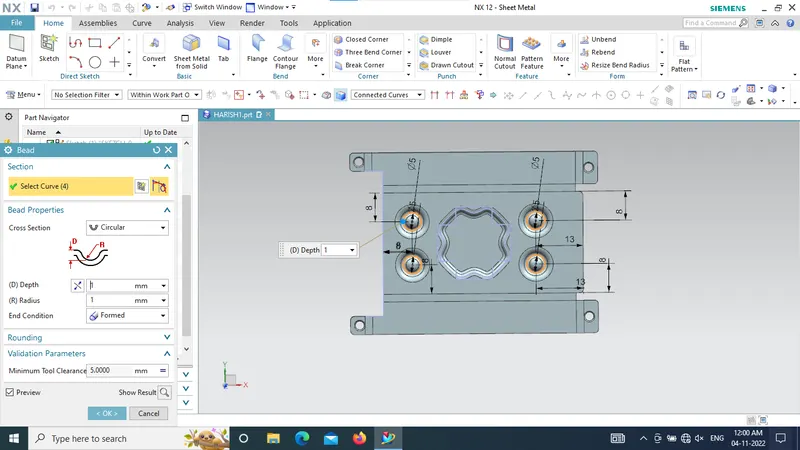
- This feature in the sheet metal modelling gives the required stiffness to the sheet metal part. This feature lifts the material along the contour of a sketch that simulates a stamping tool. The sketch can be either opened or closed sketch. In this project, a circle of the required diameter was drawn on an unbent blank as shown in the figure below. Then the bead feature is applied with the required depth. Later the bead and its sketch were mirrored about the YZ plane. Then these two beads were selected and mirrored about the XZ plane.
Rebend:
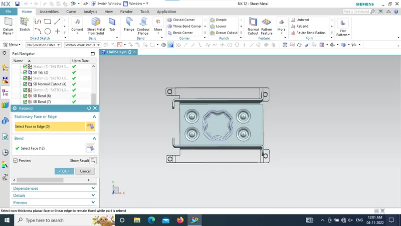
- This feature restores an unbend feature to its previous bent state, along with any features added after the unbend feature. This completes the process of casing design and adding the features.
Flat pattern:
- This creates a flat pattern feature from the formed sheet metal part. This 2d representation of the sheet metal model consists of all the tooling parameters. Flat patterns show bend lines, bend zones, punch locations, and the shape of the entire part with all bends flattened and bend factors considered.
Drafting:
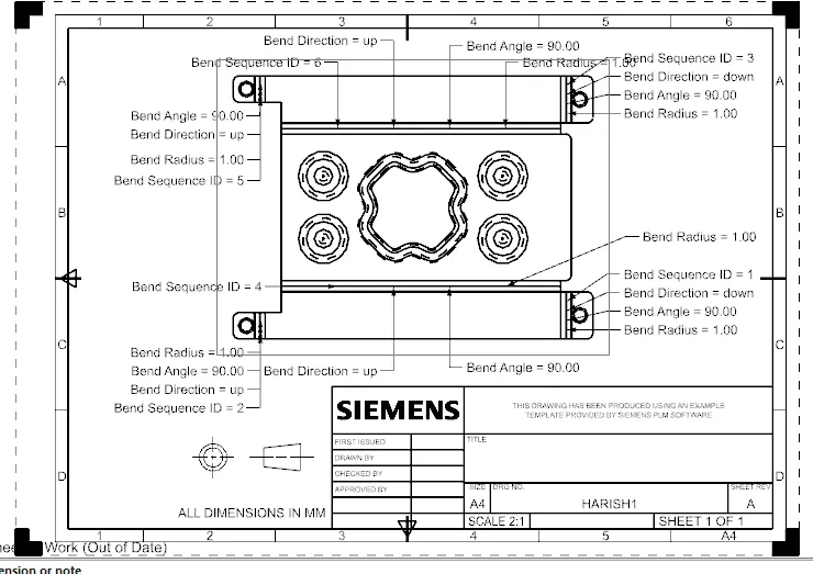
- Once the design was completed, manufacturing of the component requires technical drawing with provided scale and accuracy. The necessary details such as bend table, annotations and other parameters were defined as per the requirement.
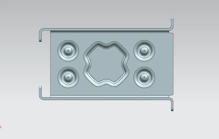
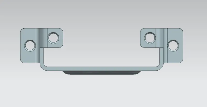
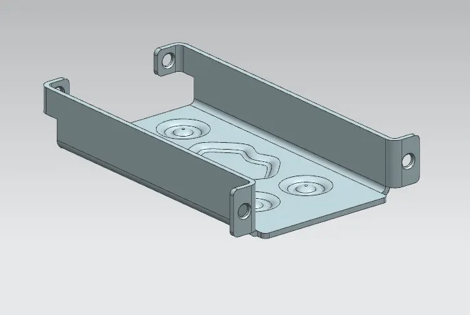
Different views of the model:
Top View :
Front view :
Isometric View :
Conclusion:
-
In this project, we have understood the user interface of the Siemens NX software and the commands used in the software. We have designed the casing using advanced sheet metal and drafted the flat pattern of the sheet metal model consisting of tooling parameters that can be used on the shop floor to manufacture the product.