Advanced Sheet Metal Design Using NX Cad Challenge_1_Casing Design
CASING DESIGN:
Objective:
To design the sheet metal component using sheet metal modelling tools.
Introduction:
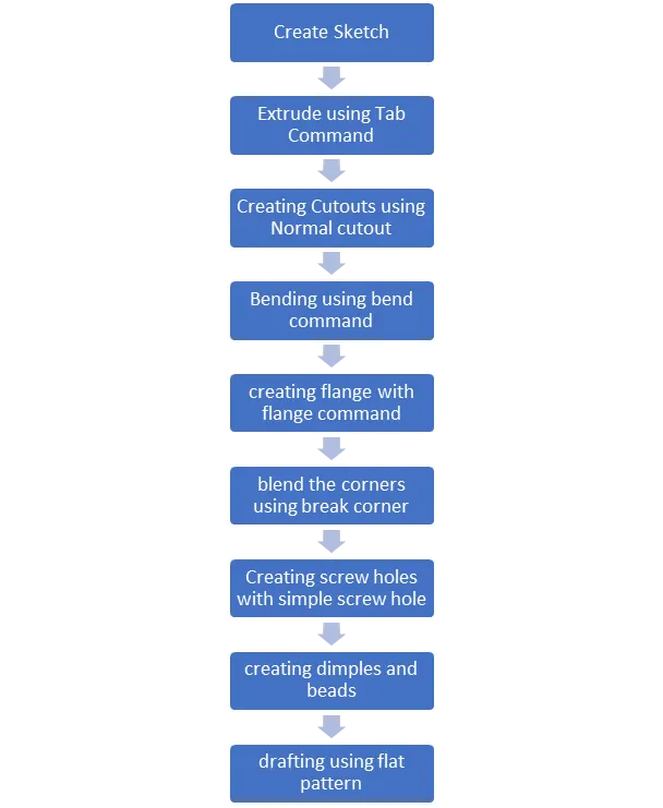
Sheet metal Component modelling is the creation of sheet metal parts by converting existing parts, extruding sketch curves (including arcs and splines to create rolled sheet metal), or thickening faces or sketches. All operations on active sheet metal models are automatically represented as a flat pattern, and joints and bends are listed in a sheet metal table.
Design Methodology:
Sketching:
Sketching is a basic drawing tool which is used to make the primary face of the model from which the various 3 D commands are been done.
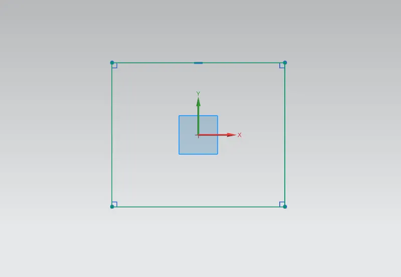
Tab:
Tab is the Extrude command which converts the sketch into the 3D object with the thickness.
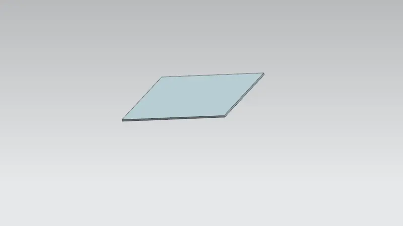
Normal Cutout:
Normal cutout is made using the sketch drawn and make the paticular sketch area to remove from the element.
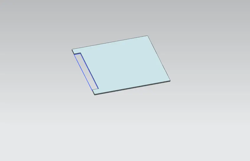
Bend:
Bend is command that used to bend the sheet metal.
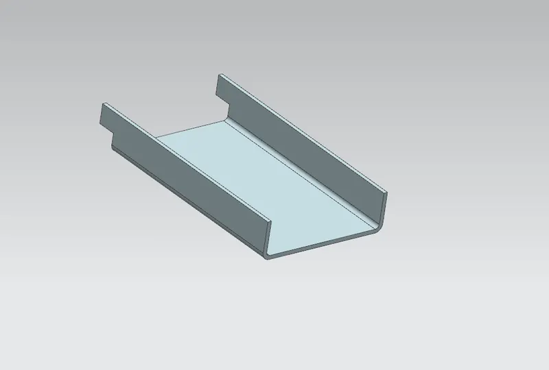
Flange:
A flange feature consists of a face and bend connected to an existing face along a straight edge. This is feature can be created using the Flange command.
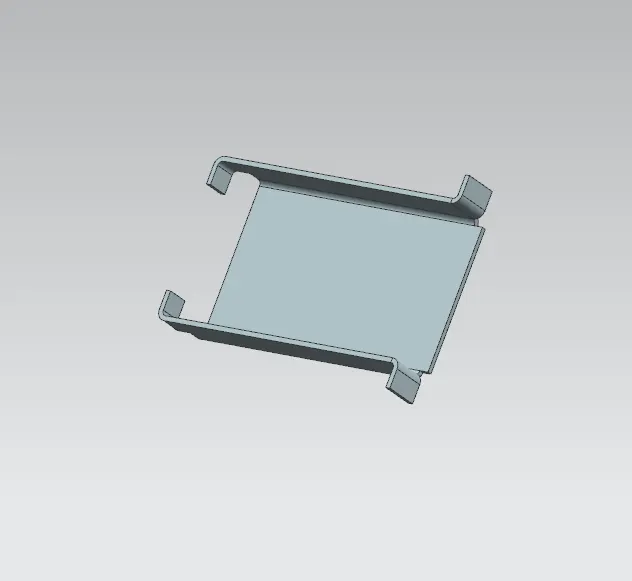
Break Corners:
Make the sharp corners to blend and make a corner in round.

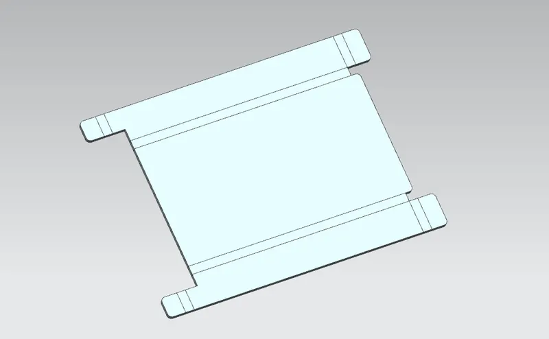
Unbend:
Unbend is the feature helps to view the sheet in the flat manner before all the process.
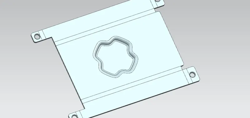
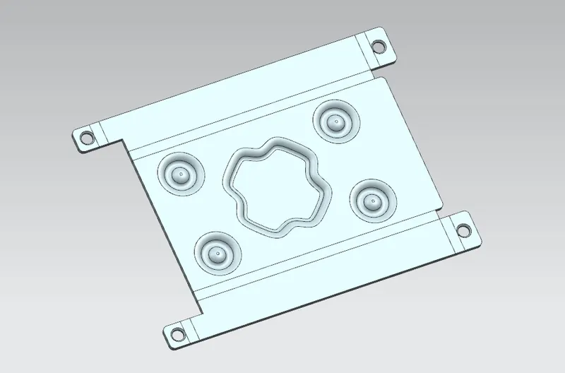
Dimple:
Dimple creation is lifts the particular area as designed in the sketch this helps to create the submerged region in the sheetmetal
Beads:
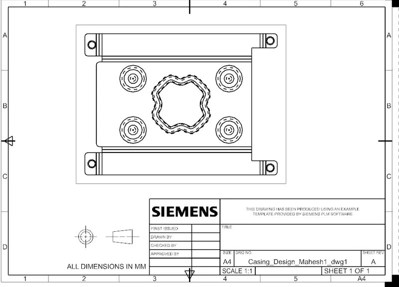
Drafting:
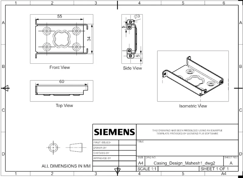
Drafting is the 2 D model which is used in the manufacturing process. this is creating using the drawing modeling in NX cad and this makes the 2D model as requied.
Views of the Model:
FRONT VIEW:
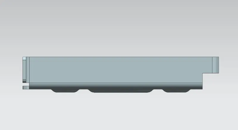
SIDE VIEW:
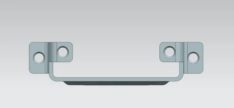
TOP VIEW:
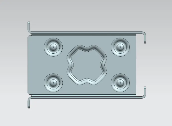
ISOMETRIC VIEW:
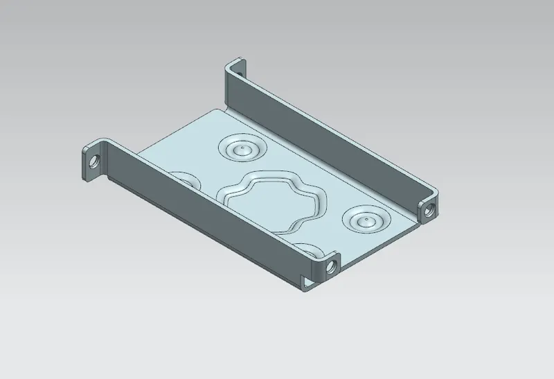
CONCLUSION:
From the above challenge we can get the clear idea of the sheet metal modeling using NX CAD.
- Models are attached below
- Google Drive
- ZIP Fil has been attached.