Advanced Sheet Metal Design Using NX Cad Challenge_1_Casing Design
Advanced sheet metal design using NX CAD Challenge 1 Casing Design
Objective: To design a Casing with the help of NX advance sheet metal.
Introduction:
NX Sheet Metal Provides a set of tools within the NX design environment that allows for simple and fast designing of sheet metal parts, dependent on their material and process information in sheet metal- specific modelling features: bends, flanges, Tabs, cutouts, beads, dimples, louvers, corner and edge treatments, Patterns and other formable features,
We can also Quickly convert solid models to sheet metal components, and create sheet metal parts that enclose other components.
NX Sheet Metal-Specific features such as flanges, tabs, jogs, corner conditions, and Drown cutouts & many more along with productivity enhancements such as automatic bend reliefs.
So, in this Project I am going to design a casing by using sheet metal tools and commands,
Design methodology/ approach
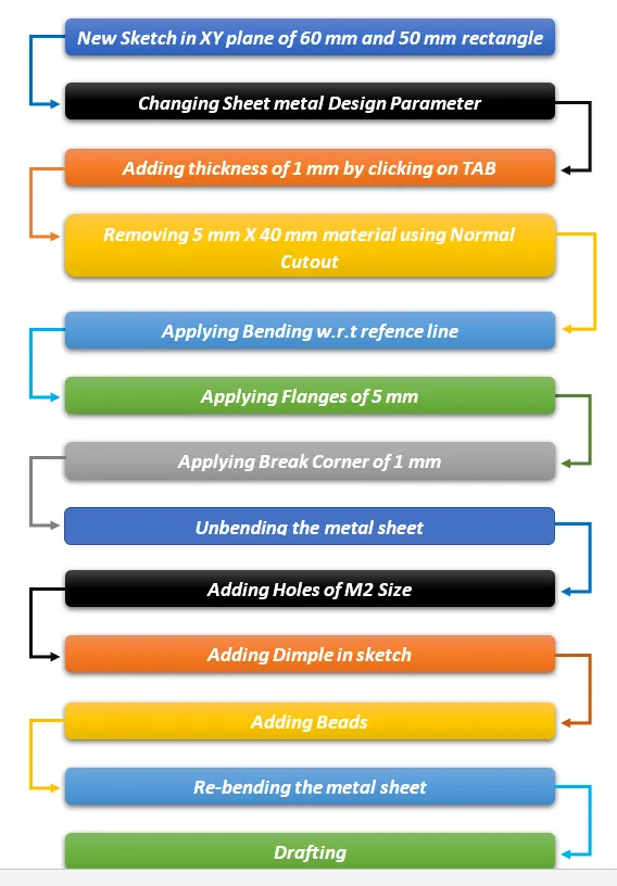
Description
The Important tools which used during designing of casing are as follow:
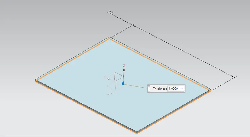
- TAB: Creates a base feature by extruding a sketch along a vector by a thickness value or adds a material to a plane face.
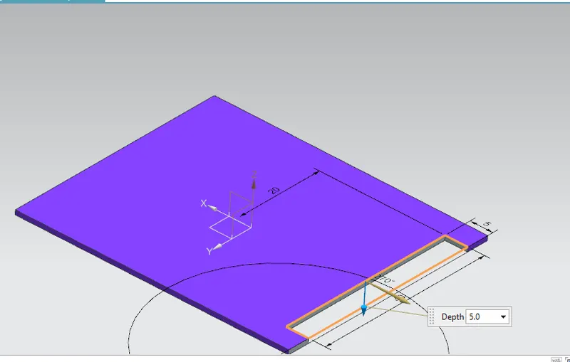
- Cutout: Cuts the model perpendicular to the sketch.
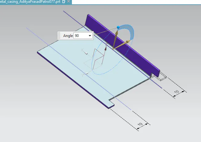
- Bend: Modifies the model by bending material on one side of a sketch line adding a bend between the two sides.
- Flange: Adds a flange to an angle to a planner face and adds a bend between the two.
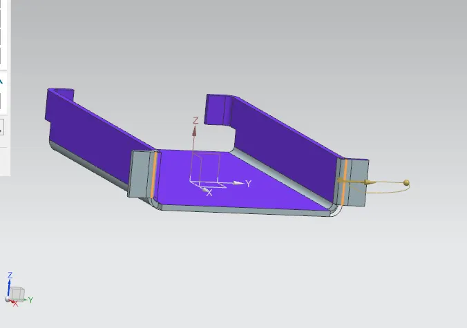
- Break Corner: Rounds a Sharp corner.
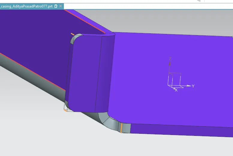
- Unbend: Flattens a bend.
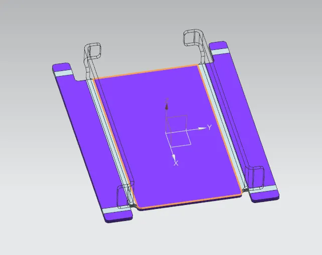
- Hole: Hole Command use to create a hole on one or more solid bodies in a part or assembly with option for counterbored, Countersunk, and threaded.
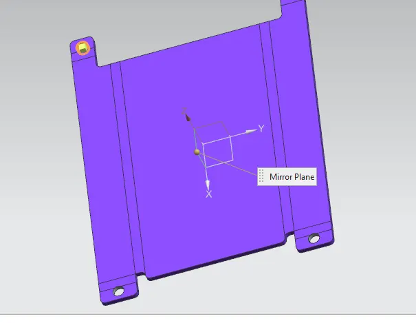
- Studio spline: Creates spline through defined points. We can change positions of points or drag points while the command has been activated.
- Move Curve: We can move our sketch entities according to selected reference and reference points, which makes moving sketch objects very effective.
- Dimple: Lifts an area of the model inside a sketch that simulates stamping a tool.
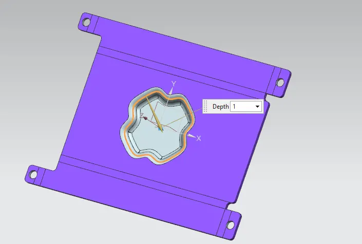
- Bead: Lifts a material along a counter of sketch that simulates stamping a tool.
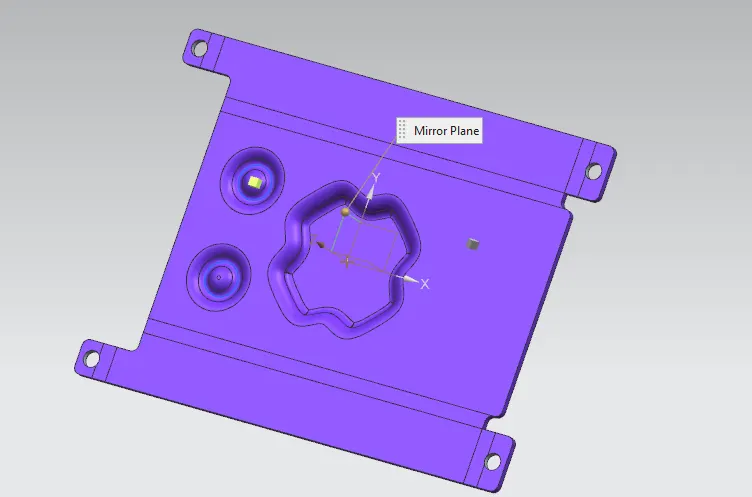
- Mirror feature: used to mirror w.r.t plane or reference.
- Re-bend: Restore the bend.
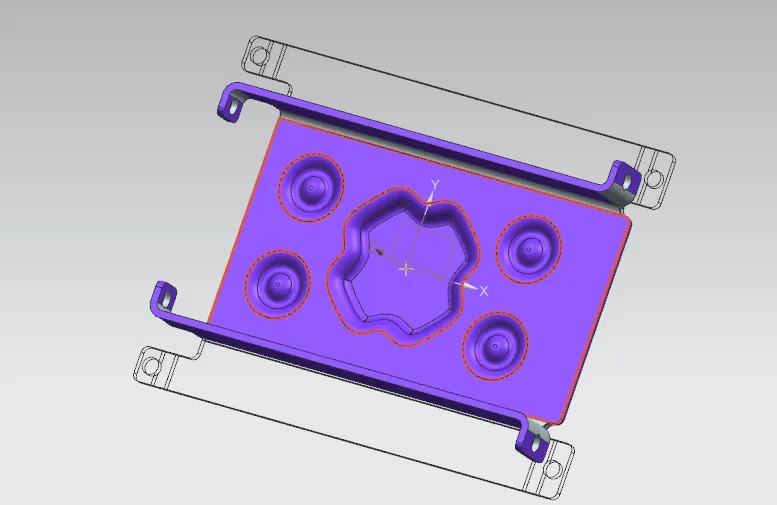
- Flat pattern: Create flat pattern feature from the formed sheet metal part.
- Base View: Used to create model view on the sheet.
Screenshots of the model:
Isometric:
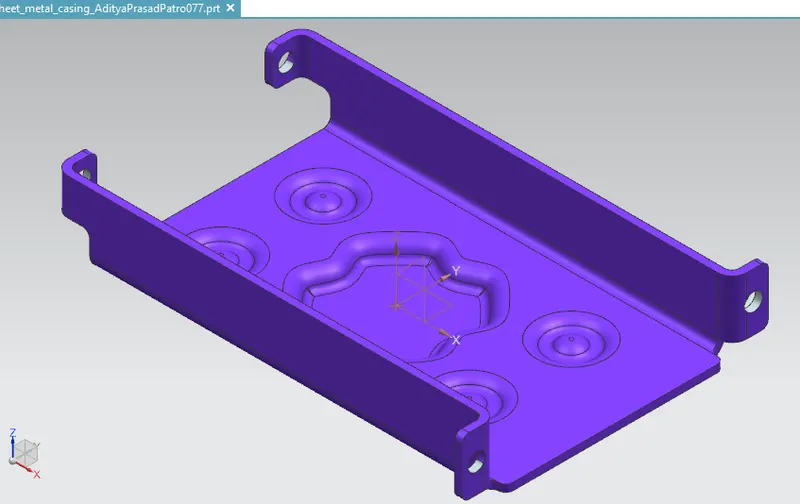
Front:
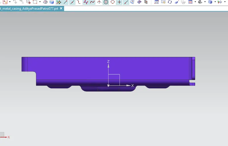
Side:
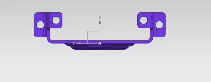
Top:
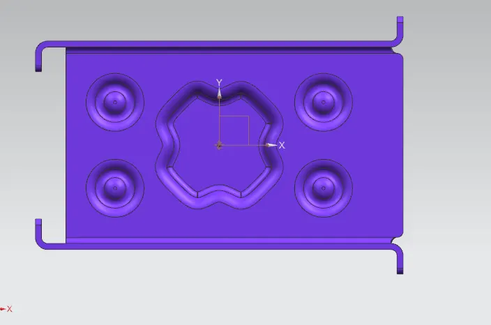
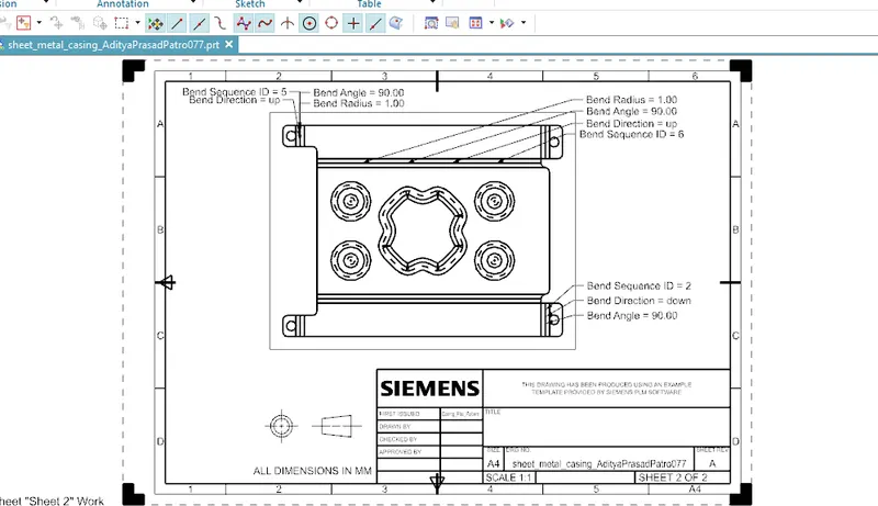
Attach Detailed drawing sheet image
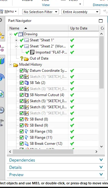
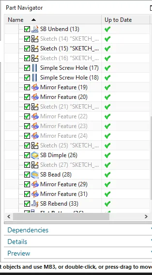
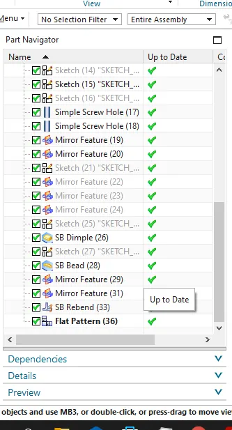
Part Navigator
Conclusion:
While designing a casing I have understand and learnt different tools such as Tab, Flange, Dimple, Bending, Unbending and many more in sheet metal N