Advanced Sheet Metal Design Using NX Cad Challenge_1_Casing Design
CASING DISIGN
Objective:
The objective of this project is used to create a model of Casing Design using Siemans NX cad.
Introduction:
In this challenge, by using NX sheet metal application to design the sheet metal casing by using various tools like a tap, flange, normal cutout, bend, dimple and bead.
Design Methodology:
The following of the CASIGN DISIGN are modeled in Siemans NX cad.
- Sketch
- Tab
- Normal cutout
- Bend
- Flange
- Break Corner
- Unbend
- Hole
- Dimple
- Bead
- Mirror feature
- Reband
Description:
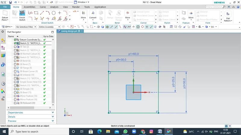
SKETCH
Sketch is the Two dimensional representation of the model with respect to the plane/view from the outside of the model. In NX cad there are different sketch options available to create a sketch. The following sketch options available in NX cad Line, Arc, Circles, Rectangle, etc... .
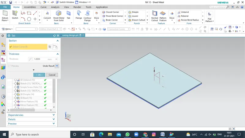
TAB
Tab is use to create a base feature by extruding a sketch along a vector by a thickness value or by adding material to existing faces and bend regions of a sheet metal part.
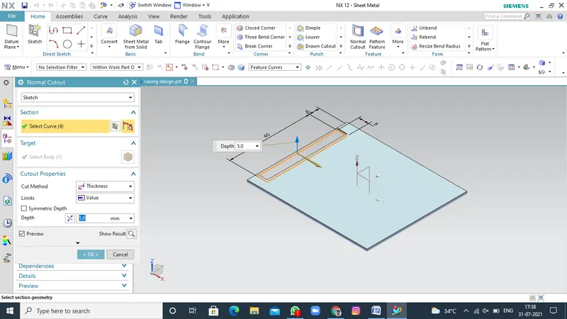
NORMAL CUTOUT
Normal cutout is used to extracts volumes from sheet metal production principles. Cutting faces will be perpendicular to the sheet metal surface.
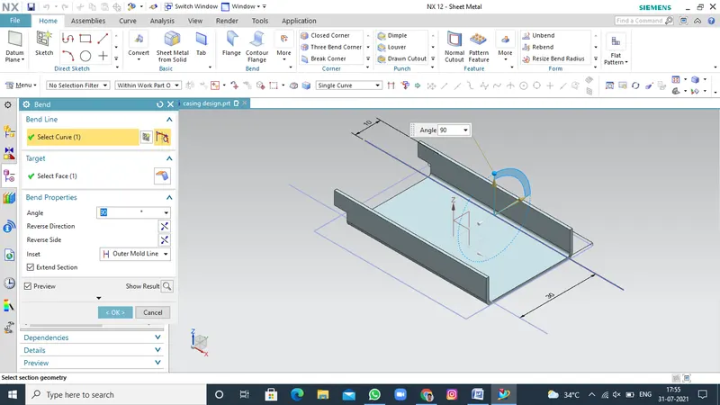
BEND
Bend command is used to create a bend the sheet along a sketch profile. It is create some angle of bend the sheet metal along a sketch profile.
FLANGE
Use this command to add a flat flange at an angle to a planar face and add a bend between the two. A flange consists of a bend region 1 and 2.
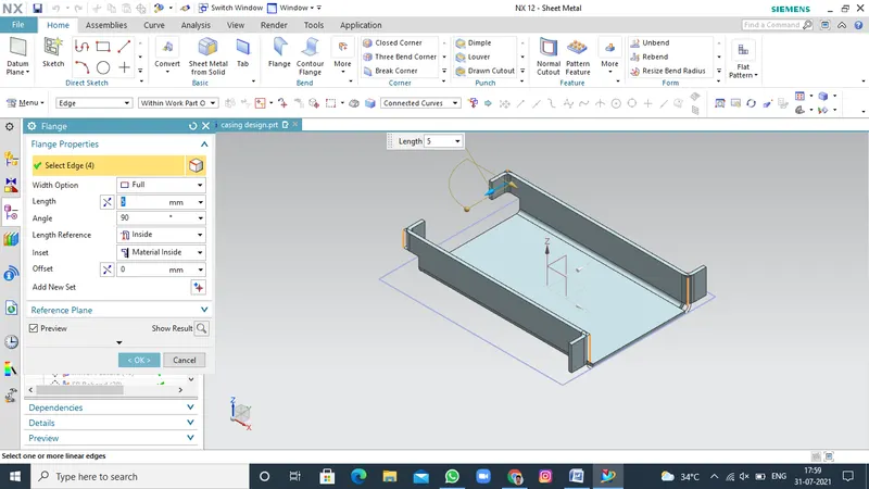
BREAK CORNER
The break corner command is use to create the round or chamfer sharp corner of a tab or flange.
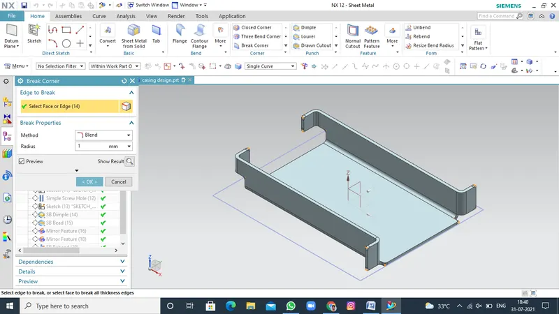
UNBEND
In this command use to bend area is form to unbend the sheet metal. First the stationary face is selected after the bend area selected it will formed unbend.
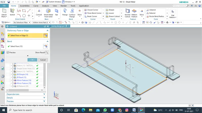
HOLE
The NX cad has a command that user could create or drill standard size holes with it. This command hole and you can active this command by clicking on it. You can create various kinds of hole that generally used in mechanical structures according to accepted standards.
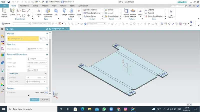
DIMPLE
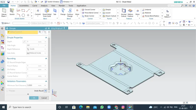
The dimple command use to lift an area of the model inside a sketch that simulates a stamping tool.To create an indentation in a sheet metal part casing a sketched section as the dimple outline.
BEAD
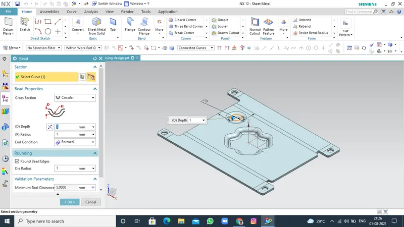
Bead - It lifts material along the contour of a sketch that simulates a stamping tool, it is used for giving strength to the sheet metal.It is create some angle of bend the sheet metal along a sketch profile.
MIRROR FEATURE
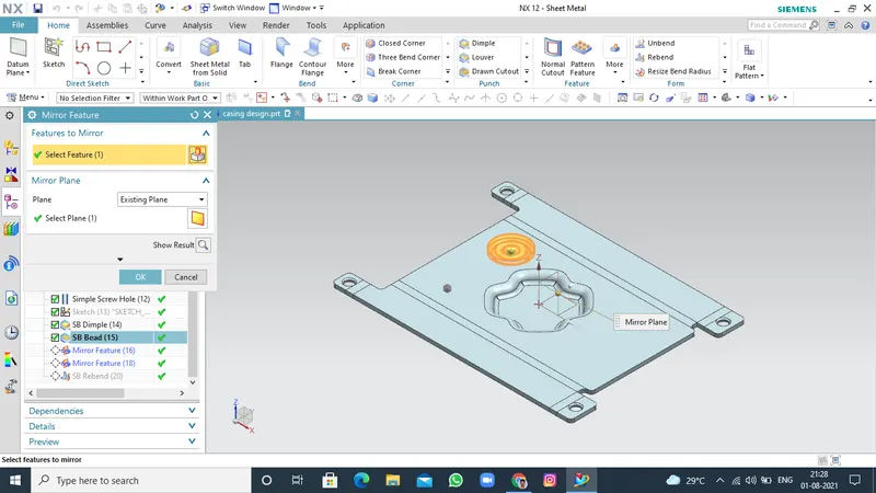
“Mirror Feature” is the command, copies, and pastes features on the model by mirroring through plane or surface.
REBEND
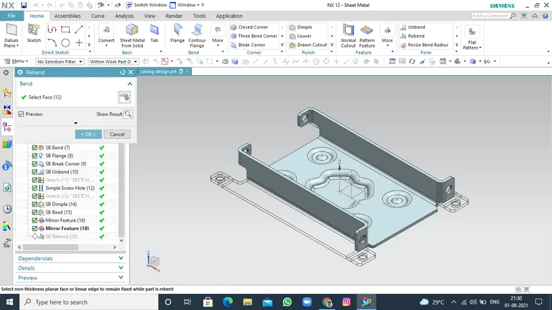
Use the rebend commands to unbend and rebend non-uniform thickness bends.
Views of casing design:
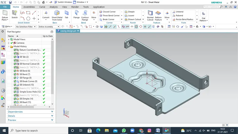
Isometric View
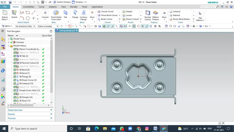
Bottom View
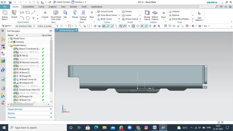
Front View
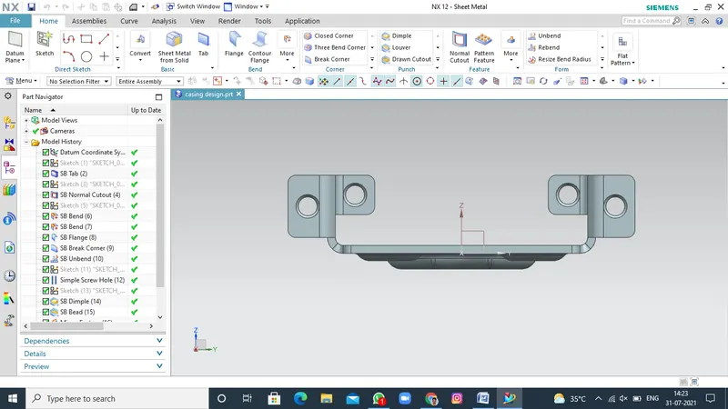
Right Side View
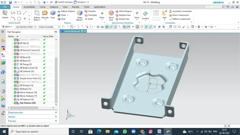
FLAT PATTER VIEW
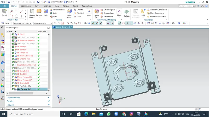
studio view
Conclusion:
By using various commands in sheet metal design Casing Design is created by various features.