Additional Project (FSI Aerothermal-analysis of missile at High Mach no.)
AIM:
- Analyzing a missile with a high Mach number combined with engineering data added to the missile and doing structural analysis.
OBJECTIVE:
- (CASE-1) To create the geometry and meshing domain of a missile and analyze the shock waves encountered for Mach No. 6.
- (CASE-2) To do structural analysis by adding material to the missile using engineering data and by importing thermal load from the Fluent case file and analyzing the structural results of the missile.
THEORY:
- A missile is an intelligent unmanned rocket designed to carry the payload to a designated point with an aim of destroying the object/target. The missile is designed keeping in mind its target, trajectory, warhead, range, velocity, and launch platform.
The major technologies/mechanisms used in a missile are:
- Propulsion system
- Guidance system
- Aerodynamic features include airframe, wings, and fins
- Terminal guidance in case of precision-guided weapons
- Warhead.
The propulsion system in a missile is required to achieve terminal conditions like range, speed, and warhead-carrying capability. The missile is propelled either by rockets or jet engines using solid or liquid fuel. Some missiles use hybrid technology for propelling them to their intended point.
The function of the guidance system is to maintain the missile in its desired flight path by using an altitude control mechanism. This is done by controlling the pitch, roll, and yaw of the weapon. The guidance system operates as an auto-pilot, damping out fluctuations that tend to deflect the missile from its intended flight path.
In some missiles, the guidance commands are generated internally by the missile's computer. In others, the commands are transmitted to the weapon by some external source.
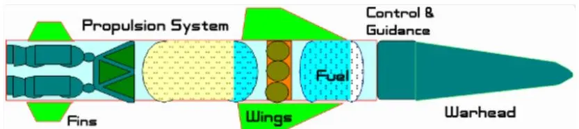
The aerodynamic features of a missile also called controlling surfaces, are used to control the missile's flight. The fins, wings and tail are the three major aerodynamic control surfaces used to steer the missile. The missile's course can be altered by moving these controlling surfaces.
In the case of precision weapons, the target seeker comes into the picture when the missile starts detecting its target. The mechanism also works to determine the time of activating the warhead. After finding out the target, the device sends an electrical impulse to trigger the activation system. The target seeker is based either on radar or infrared (IR) or laser devices.
The warhead of a missile is selected keeping in mind its target type. It inflicts damage on the target and determines the missile's lethality. An optimum position of burst is used to achieve the desired effect on the target limits the closer the burst to the target, the smaller the warhead needed. In other cases where the missile is required to cause destruction on hard targets, before the detonation of the warhead, penetration is achieved by employing a variety of technologies.
SETUP AND SOLUTION:
- (CASE-1) To create the geometry and meshing domain of a missile and analyze the shock waves encountered for Mach No. 6.
GEOMETRY:
- As we mentioned above, there are various types of missiles. Hence, to create the geometry of a missile, here by using the below two reference images, the model has been developed as per my own design.
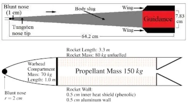
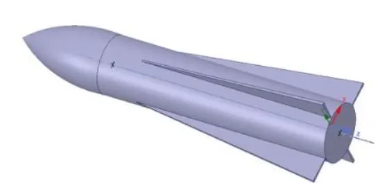
- The geometry was created in SpaceClaim separately and saved externally to work in the different cases.
- Now the geometry is imported into the workbench.
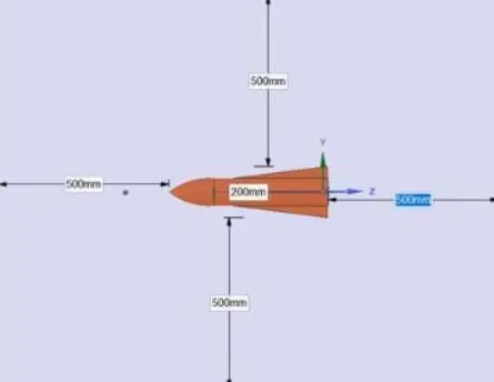
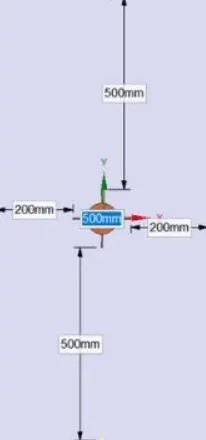
The enclosure was created accordingly with the following measurements.
MESHING:
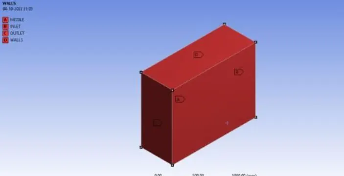
- In this meshing we can assign the named selection for Inlet, Outlet, Symmetry wall, and Predator Wall, We can use the different types of meshing processes for this model.
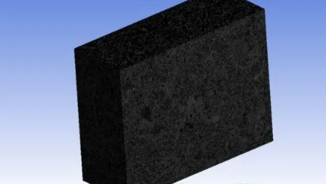
- Meshing will be done for the outer enclosure chosen as a method of the Multizone and this will create the mesh, The element size used for this is 5 mm.
- For the inner enclosure, we choose the body sizing method to make more refinement.
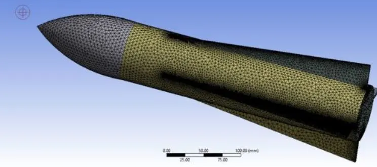
- MESHING for Missile.
- MESHING for Enclosure,
- Statistics:

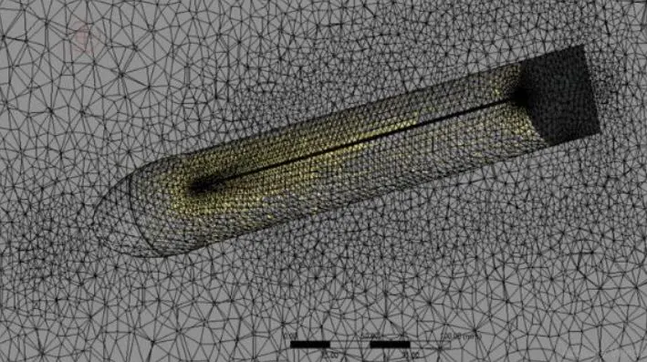
- Sectioning plane:
- NAMING SELECTION:
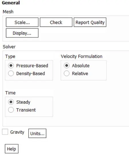
- Solver type: Pressure based
- Check the Energy equation
- Turbulent Model: K-Epsilon, Realizable, Standard Wall Treatment.
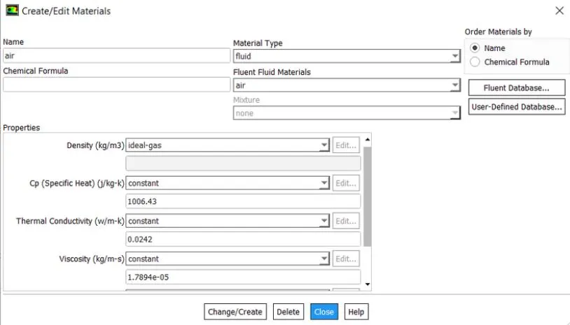
- Fluid Material: Air
Material Selection
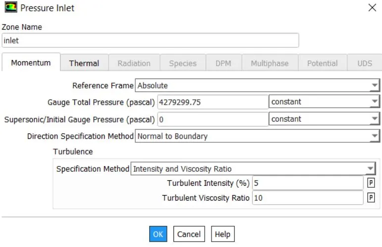
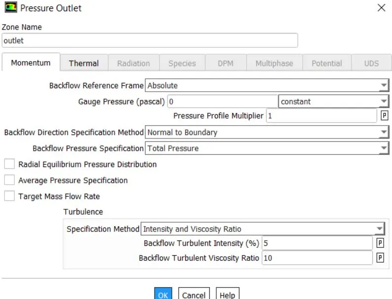
- Boundary conditions:
- For Mach no 6 the following pressure has been calculated accordingly.
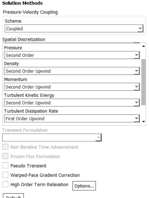
- In the solution method, the second order upwind is selected,
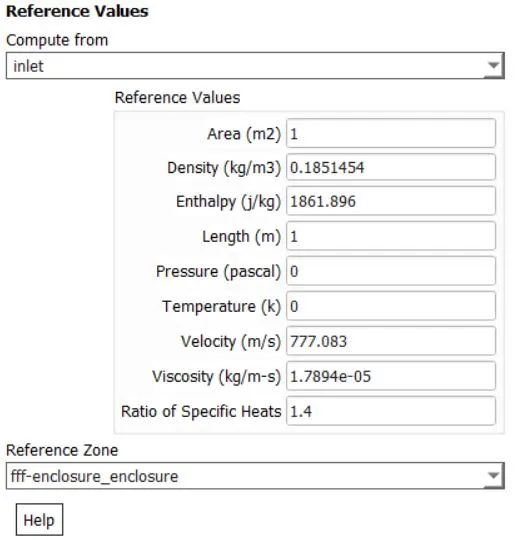
Reference Value
RESULT: (CASE-1)
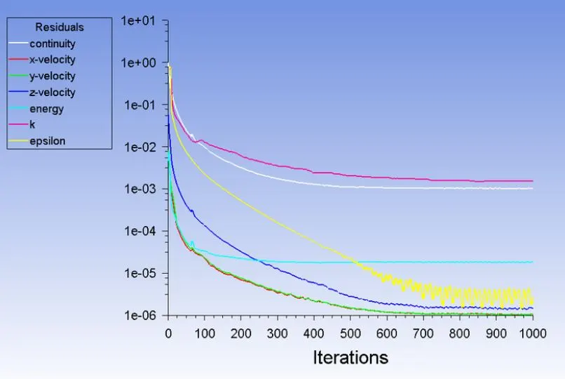
- Residual:
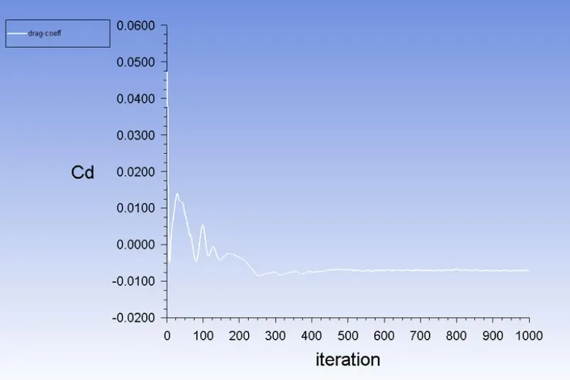
- Drag Coefficient:
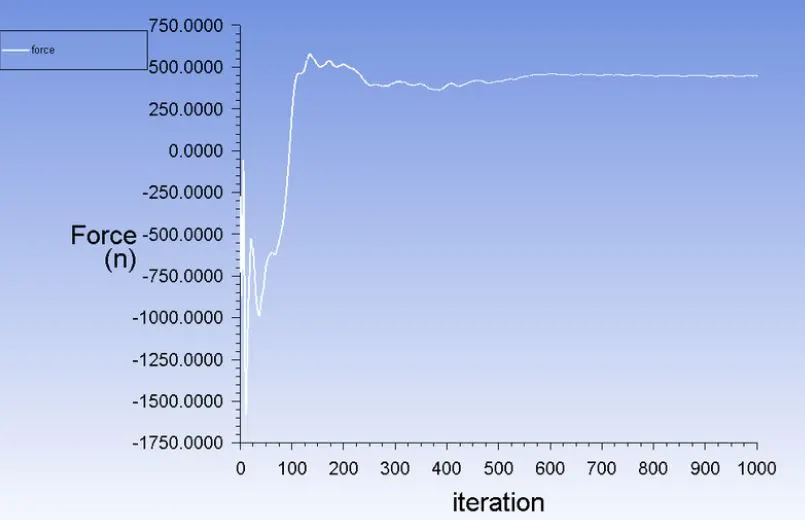
- Drag Force at Y-axis:
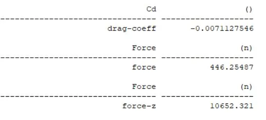
- Computed values:
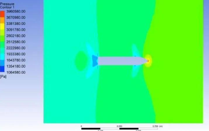
- Pressure Contour:
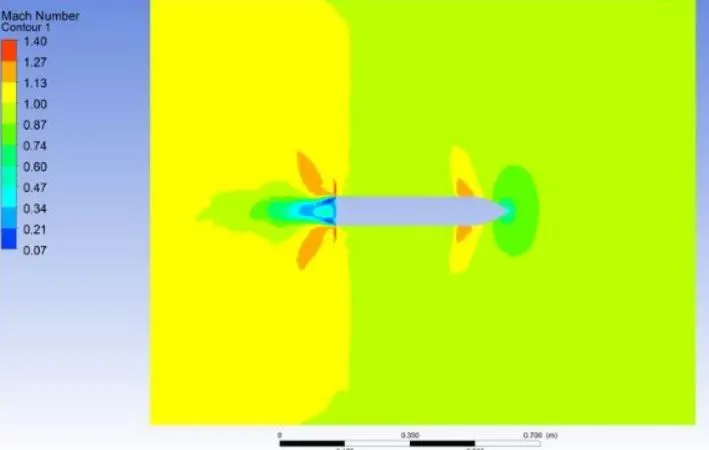
- Due to high MACH no 6, we can see the shock waves formed around the walls.
- MACH NO:
- The maximum Mach number acted along at the body is 1.40
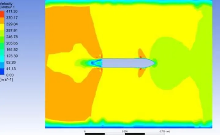
- Velocity Contour:
SETUP & SOLUTION: (CASE-2) To do structural analysis by adding an additional material to the missile using engineering data and by importing thermal load from the Fluent case file and analyzing the structural results of the missile.
- The Same geometry file has been imported to static structural. NOTE: Here the missile body is extracted from all other parts, and the body part is only imported to do the structural analysis
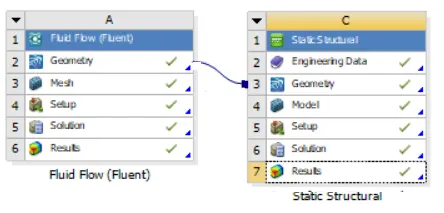
- Here in the B division, faced some errors while expressing the unwanted bodied. so I duplicated the entire structure and worked.
- To import the engineering data the following materials are added to the model.
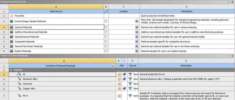
- The material is selected and ready to import to the geometry.
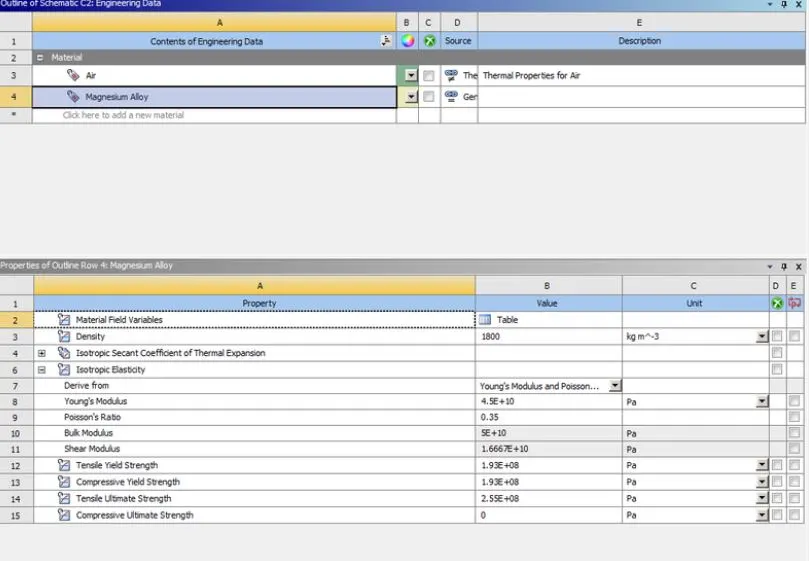
- Here Magnesium alloy is selected because Magnesium alloy developments have traditionally been driven by aerospace industry requirements for lightweight materials to operate under increasingly demanding conditions. Magnesium alloys have always been attractive to designers due to their low density, only two-thirds that of aluminium. This has been a major factor in the widespread use of magnesium alloy castings and wrought products.
Key properties of magnesium alloys:
- Lightweight
- Low density (two-thirds that of aluminium)
- Good high-temperature mechanical properties
- Good to excellent corrosion resistance
GEOMETRY:
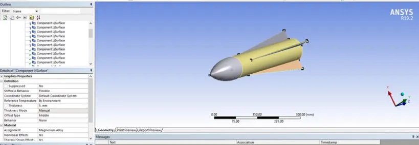
NOW, Suppress the unwanted body and provide the material and the thickness for the component as follows.
MESHING:
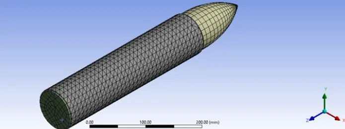
- The default element size has been given and the meshing has been initiated, as we can see below.
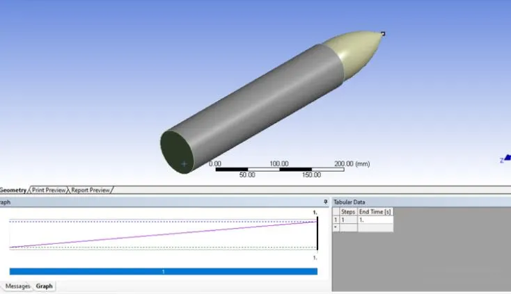
- The analysis is done for only a one-time step as it is already a default setup.
- For the solution, I went through my know method to do the structural analysis as follows:
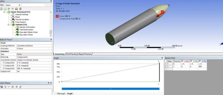
- Force is acted along the z-axis. with a user-defined value of 900 N.
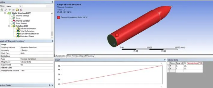
- The thermal condition is given from a reference value of 20 to 50 degrees Celcius applied along the body as we can see below.
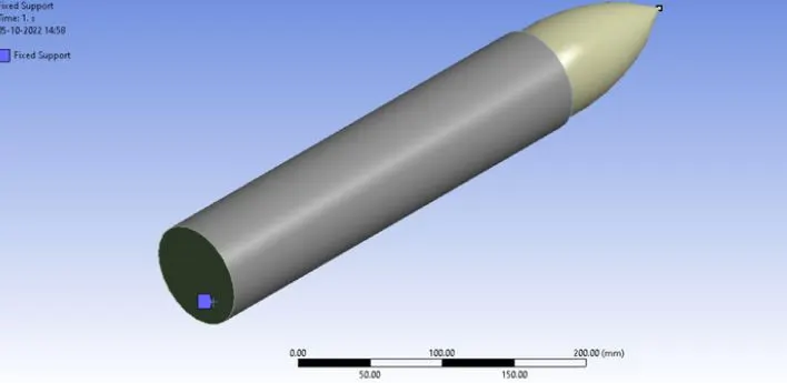
- Inserting fixed support;
- Applying the following properties to do the structural analysing.
- Total deformation:
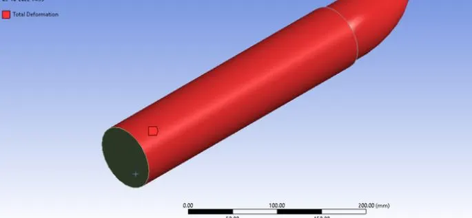
- Stress and Strain Properties:
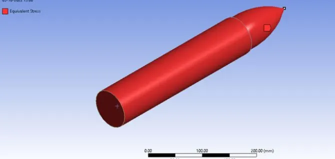
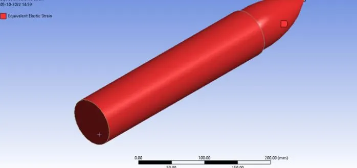
RESULT: (CASE-2)
- Total Deformation:
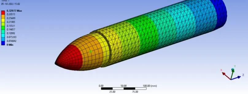
The maximum deformation was 0.32977 mm
CONCLUSION:
- The geometry and meshing domain of a missile and analyse of the shock waves encountered for Mach No. 6. were analysed with the proper report definition plots and contours.
- The structural analysis by adding an additional material to the missile using engineering data and by importing thermal load from the Fluent case file and analysing the structural results of the missile was also analysed.