A pillar Design with Master Section
WEEK 11 - A PILLAR DESIGN WITH MASTER SECTION
TOOLING AXIS CREATION :
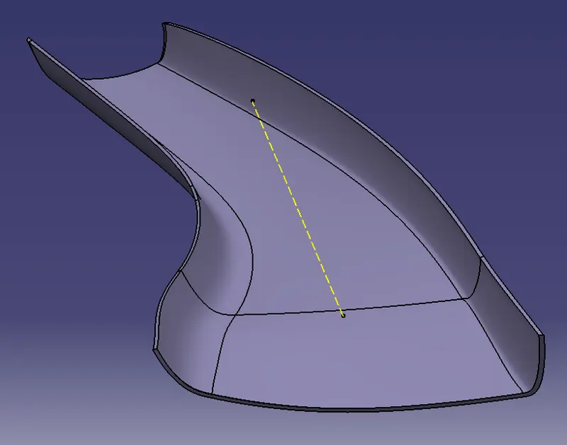
Tooling axis is the direction in which mould travels. basically there are two pieces for mould,one cavity side and one possess projections of the component. the draft angle given for the component for ease of ejection, is drafted with reference to this tooling axis.
conducted visual inspection initially, then checked for,if there is any gaps or corrections by taking boundary of the component.placing tooling axis perpendicular to the largest flat area of the component is more convenient for manufacturing. but for the given inputs, respecting the dog house, extracted side face lines of dog house from given master section and bisected. bisected line is selected as main tooling axis and proceeded to draft analysis to check for the validity of the tooling axis.
DRAFT ANALYSIS ON CLASS A
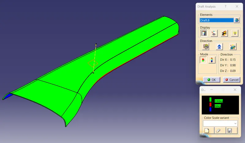
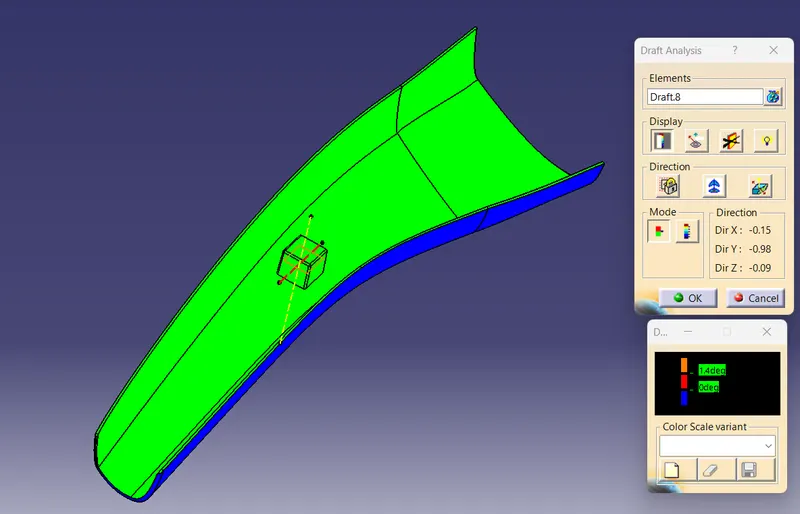
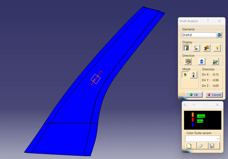
By performing draft analysis on the given class A surface enables to know wheather the component is easily removable or not and the tooling axis which we created is apt for manufacturing . this analysis is based on colour ranges which indicates different colours for different angles.
- go to customize view parameter and select material mode in mesh
- select feature draft analysis from analysis option by going in insert option from tool bar
- place the compass align to tooling axis with the help of compass tool
- select the surface
- click display button on the window
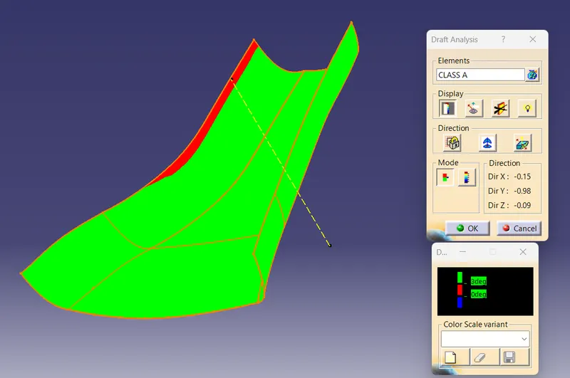
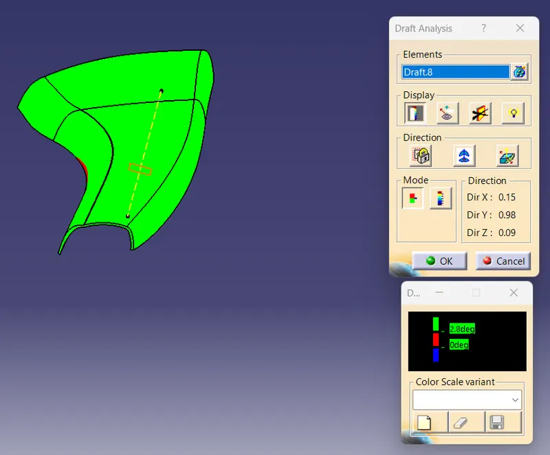
for the given class A surface one edge is less than the nominal draft degree which is 3 degree.it is indicated by red colour
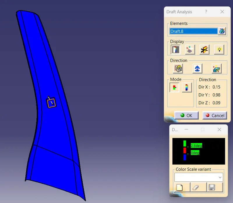
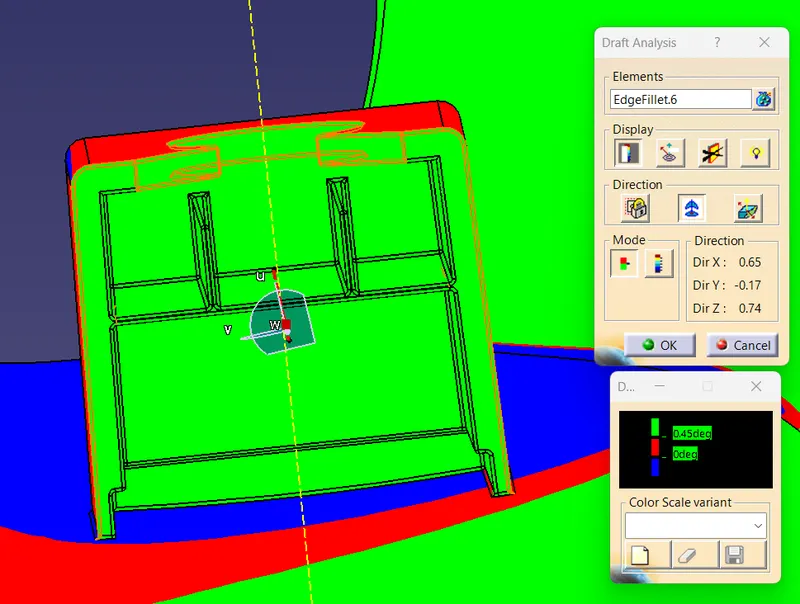
each colour zones indicates each drafting angles,green indicates within given draft angle , red indicates zero and blue indicates negative angle
CREATION OF CLASS B SURFACE
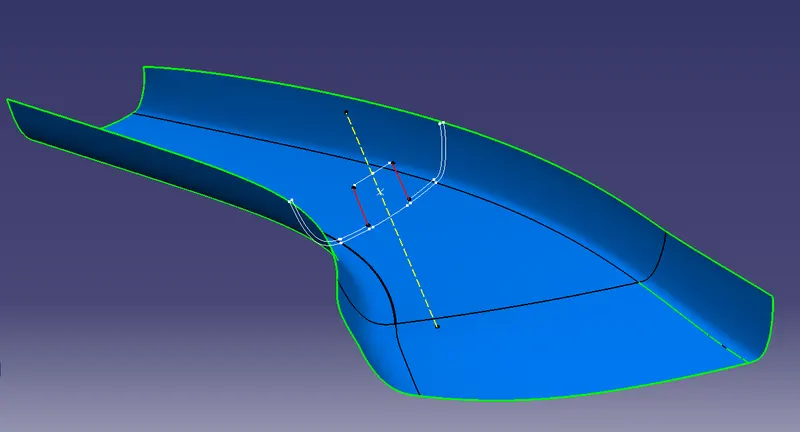
start with creating seperate geometrical set for class b, take an offset of the given class surface to a value of 2.5mm in inside direction. some patches would be there in the offsetted plane,most of the times,fillets are the cause of patches.
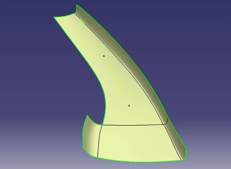
here, one curve face is missing .
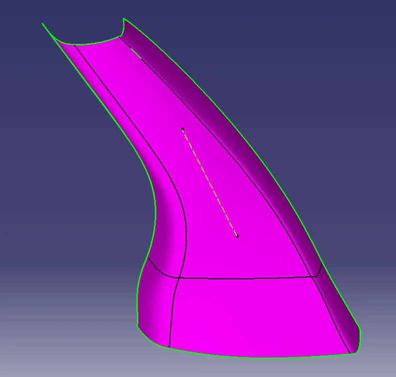
it is resolved with the help of multisection tool. thus class B surface is obtained
CLASS C CREATION:
- create boundaries at edges of class a
- select sweep with draft direction from sweep option.
- select the created boundary as guide curve and tooling axis as draft direction,with 3 degree angle projecting out from class a
- follow above sweep procedure for planes which are perpendicular to tooling axis
- for planes parallel to axis,sweep in 90 degree refence to the class a surface
- extrapolate the ends of swept planes and trim altogether to get the c surface
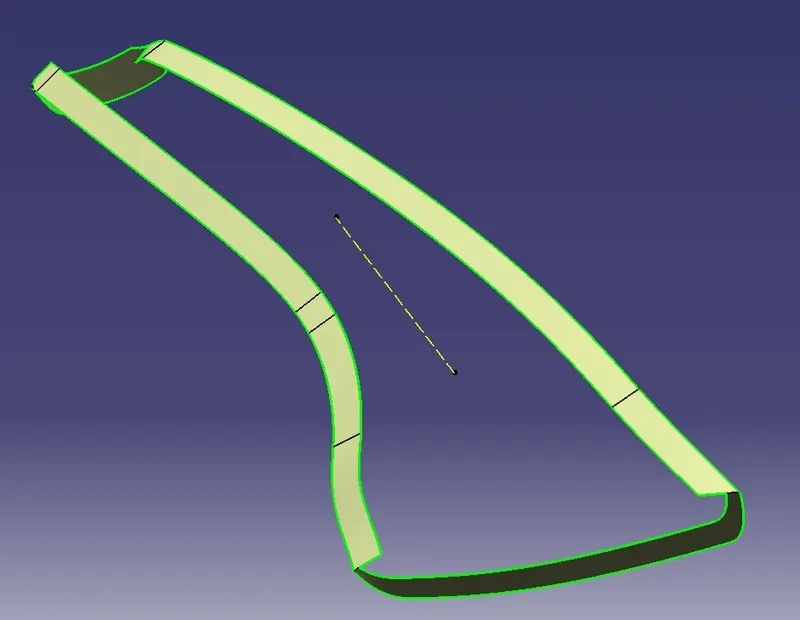
always remember to give a 1 mm of second limit when sweeping,because it helps class c to trim properly with class a.
TRIMMED CLASS A & C
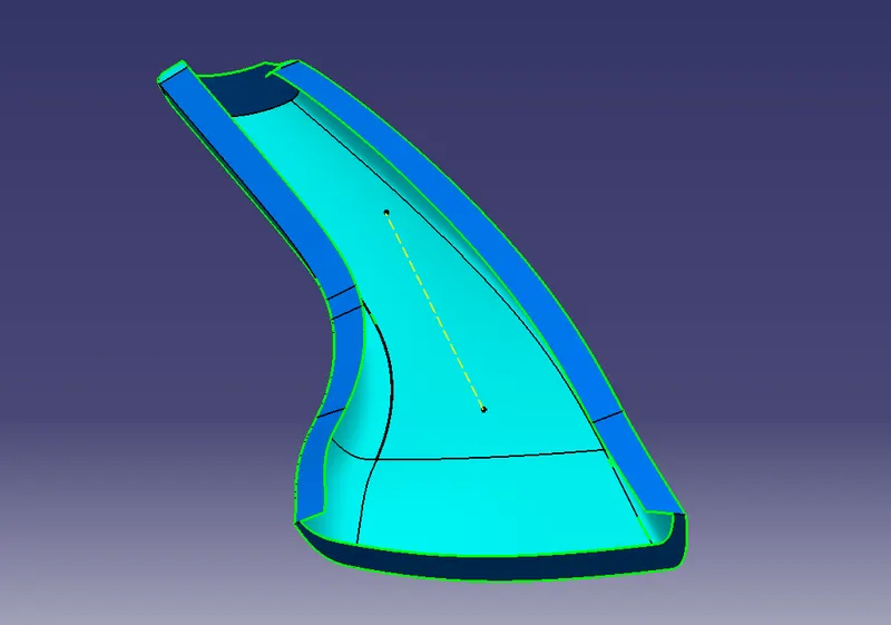
trimming class A,B & C gives final closed body
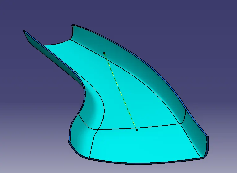
moving to part workbench, opting closed body tool and selecting our final trim obtains solid body
DRAFT ANALYSIS ON SOLID COMPONENT :
CREATION OF DOG HOUSE:
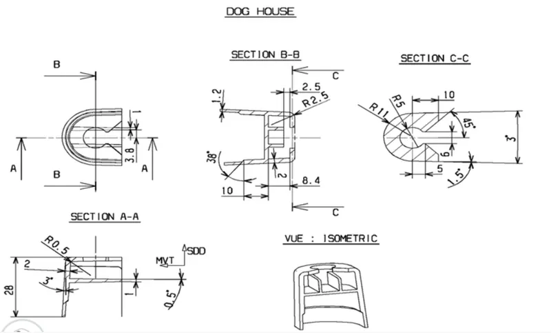
reference for dog house
PROCEDURE :
- extracted the outlines of dog house from given master section
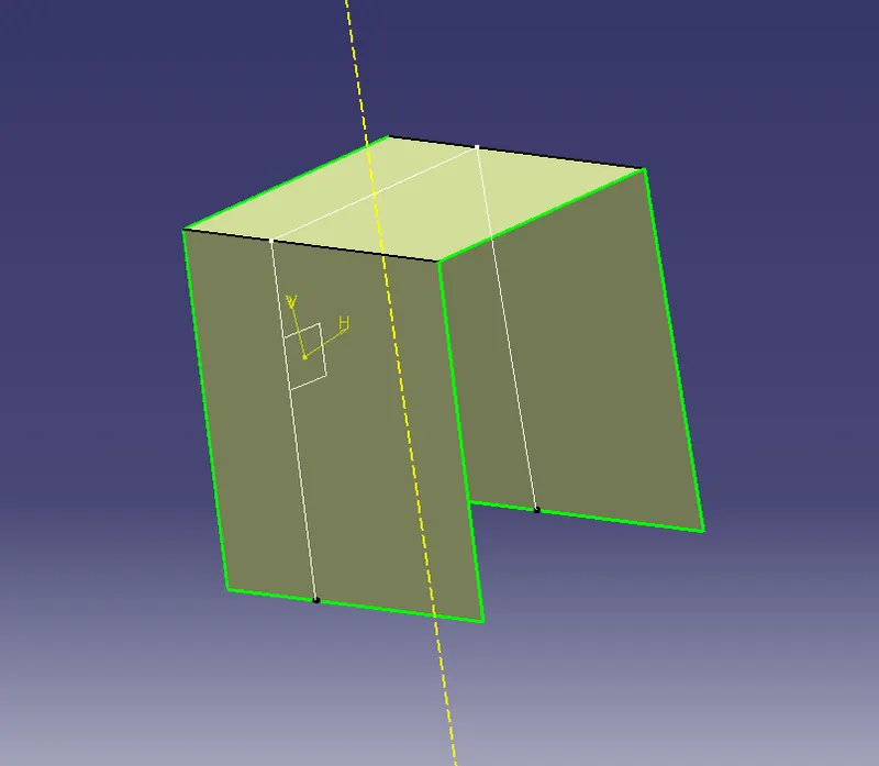
- created a plane on the curve 2 parallel to the curve.
- openend a positioned sketch on reference to the new plane and point on the curve
- extracted outlines of the doghouse and iso constrained
- extruded the sketch in shape workbench,perpendicular in direction to the plane
- created a new plane on curve 1 parellel parallel to the same curve
- opned a new positioned sketch on reference to the created plane
- extracted other outlines of the doghouse from the given master section
- extruded the sketch
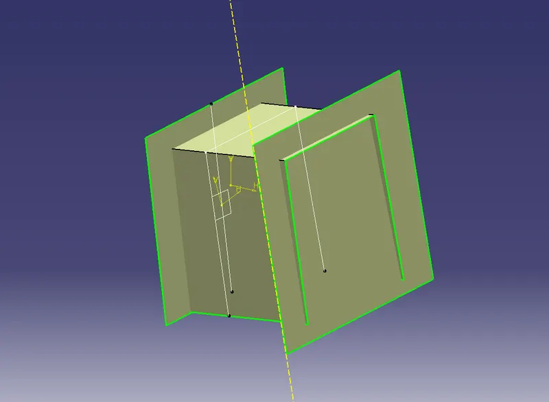
- trimmed both extruded surfaces
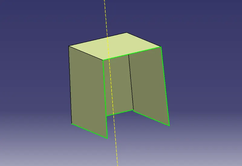
- thickened the surface using thickening tool in part workbench
- drafted and filletted the faces
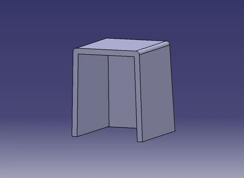
- offsetted the 2 sides and top inward to desired value
- splitted the thickened object with this surafce.
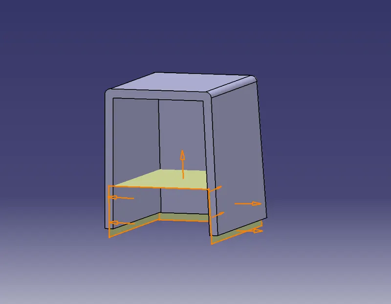
- drafted the splitted surface and filletted
- union trimmed the part with partbody selecting the projected parts beyond the closed surface as faces to remove
- opened another geometrical set
- openend a new sketch as same reference of the first sketch
- extracted the inside features of the dog house from the master section
- extruded it perpendicular in direction to the plane
- trimmed it with extruded front and rear surfaces of dog house,thus obtained a closed body
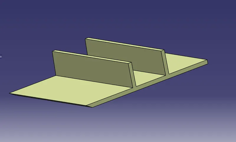
- selecting closed body tool from part workbech made this trimmed surface to a solid body
- union trimmed it with the part body selecting the projected parts beyond the dog house as faces to be removed
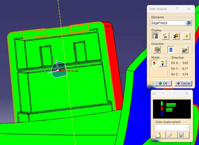
- drafted to a value of 0.5 degree and filleted to value of 0.25 radius
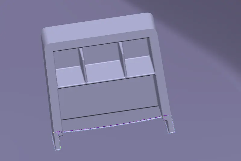
- created a new plane on the top surface of the dog house
- opened a positioned sketch on reference to this new plane
- created the drawing as shown on the given reference image of dog house with assumed values
- extrude the sketch in shape work bench
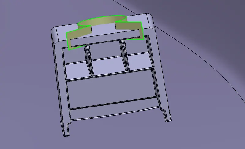
- splitted it with the closed body in part workbench
- filletted the edges
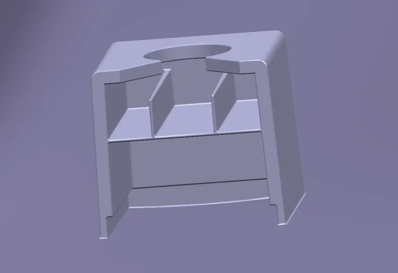
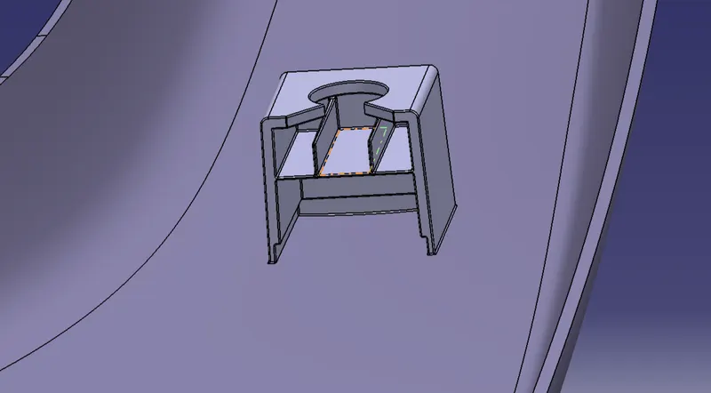
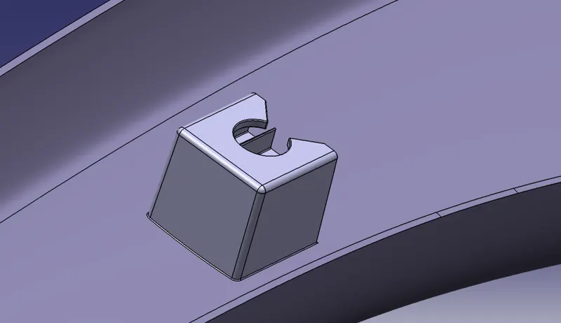
DIFFRENT VIEWS OF FINAL SOLID PART
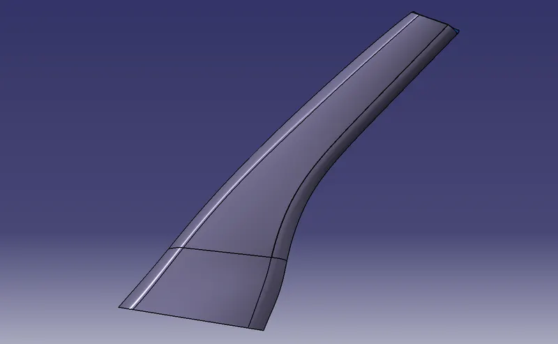
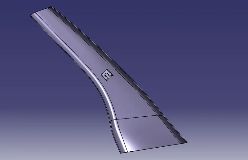
DRAFT ANALYSIS ON FINAL COMPONENT
RESPECTING MAIN TOOLING AXIS
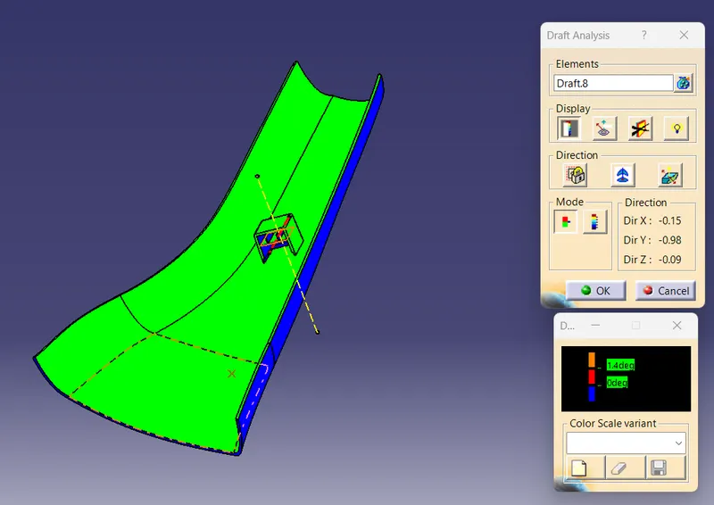
RESPECTING SIDE CORE AXIS
 KK
KK