A Matlab code for solving an Otto cycle plotting PV Diagram and calculating its thermal efficiency
AIM : To write a Matlab code for solving an otto cycle
THEORY :
ABBREVIATIONS USED :
- V: Volume
- P: Pressure
- T: Temperature
- B: Bore
- S: Stroke
- l : Connecting rod length
- cr: Compression ratio
- Vs: Swept Volume
- Vc: Clearance Volume
- a : crank radius
- R : Ratio of connecting rod length and crank radius(l/a)
Air Standard Cycle : An air standard cycle is an idealized cycle used to simplify the analysis of an engine.
Otto Cycle : An Otto Cycle is an air standard cycle used for analysis of SI( Spark Ignition) IC( Internal Compression) engine.
Assumptions used in Otto Cycle:
- Piston movement is frictionless
- Walls are adiabatic(no heat dissipation from walls)
- Working fluid is an Ideal gas(Ideal gas laws can be applied)
- Gas is calorifically perfect(specific heat values are constant)
Processes in Otto Cycle :(A four stroke engine otto cycle)
- Process 0-1 : INTAKE : The working fluid, air is drawn at constant pressure and the inlet valve is open.
- Process 1-2 : ISENTROPIC COMPRESSION : The gas is compressed isentropically, both the inlet and outlet valves are open.
- Process 2-3 : ISOCHORIC HEAT ADDITION : Heat is added through combustion at a constant volume
- Process 3-4 : ISENTROPIC EXPANSION : The gas is now expanded isentropically
- Process 4-5 : BLOW DOWN : Heat is rejected through open exhaust valve at constant volume
- Process 5-1 : EXHUAST : The products are expelled out of the cylinder through exit valve by the piston at constant pressure
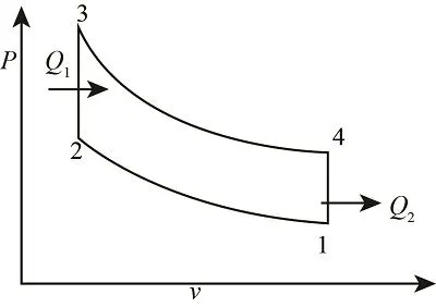
( A pv diagram for an otto cycle) (image courtesy: https://study.com/academy/answer/compare-the-otto-cycle-and-the-diesel-cycle-a-draw-the-p-v-t-s-and-t-v-diagrams-b-discuss-the-similarity-and-the-difference-about-their-thermal-efficiencies-c-based-on-these-two-cycles-draw.html)
Engien Geometry :
The main four geometry parameters for an IC engine are:
1. Bore(B) 2. Stroke(S) 3. Connecting Rod length(l) 4. Compression ratio(cr)
The piston moves from Top Dead Center to Bottom Dead Center in a loop and is attached to crank through a connecting rod both undergoing rotational movement as piston undergoes linear.
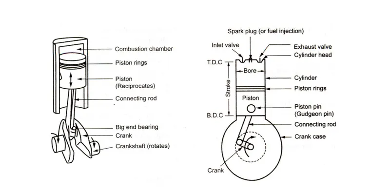
( Diagram showing Engine Geometry)(image courtesy: https://rajeshsky.webs.com/ENGINES%20MATERIALS.pdf)
KEY GOVERNING EQUATIONS :
- Ideal Gas Equation : PV=nRT
- Isentropic Relation : PV^`gamma`=constant
- Swept Volume : Vs = `pi`/4*B^2*S
- Clearance Volume : Vc= Vs/(cr-1)
- Volume change : V=Vc[1+1/2(cr-1){R+1-cos`theta`-(R^2-sin^2`theta`)^1/2}]
- Crank radius : a= S/2
- Thermal Efficiency : `eta`= 1- [(T4-T3)/(T3-T2)] = 1- 1/cr^`gamma`-1
CODE :
MAIN CODE
 % A simple demonstration of an otto cycle
% PART A GEOMETRICAL INPUTS
bore=0.1; % in meters
stroke=0.1;% in meters
con_rod=0.15; % in meters
cr=12;
% PART B OTHER INPUTS
t3=2300; % in Kelvin
gamma=1.4;
Vs=pi/4*bore^2*stroke;
Vc=Vs/(cr-1);
%PROCESS 1 ISOENTROPIC COMPRESSION
% State 1 inputs
p1=101325;
t1=500;
V1=Vs+Vc;
V2=Vc;
% State 2 parameters
p2=p1*(cr)^(gamma);
t2=p2*V2*t1/(p1*V1);
% variation of parameters during compression process
Vcomp=engine_kinematics(bore,stroke,con_rod,cr,180,0);
pcomp=p1*(V1./Vcomp).^gamma;
%PROCESS 2 CONSTANT VOLUME HEAT ADDITION
% State 3
V3=V2;
p3=p2*t3/t2;
%PROCESS 3 ISENTROPIC EXPANSION
% State 4 parameters
V4=V1;
p4=p3*(V3/V4)^gamma;
% variation of parameters during expansion process
Vexp=engine_kinematics(bore,stroke,con_rod,cr,0,180);
pexp=p3*(V3./Vexp).^gamma;
% THERMAL EFFICIENCY
eff = 1-1/cr^(gamma-1);
% PLOTTING
figure(1)
hold on
plot(V1,p1,'*','color', 'r')
plot(Vcomp,pcomp)
plot(V2,p2,'*','color','r')
plot([V2,V3],[p2,p3],'color','y')
plot(V3,p3,'*','color','r')
plot(Vexp,pexp)
plot(V4,p4,'*','color','r')
plot([V4,V1],[p4,p1],'color','b')
xlabel('Volume')
ylabel('Pressure')
FUNCTION GENERATED FOR ENGINE KINEMATICS
function [V] = engine_kinematics(bore, stroke, con_rod,cr, start_crank, end_crank)
theta=linspace(start_crank,end_crank,100);
a=stroke/2;
R=con_rod/a;
Vs=pi/4*bore^2*stroke;
Vc=Vs/(cr-1)
term1=1/2*(cr-1);
term2=R+1-cosd(theta);
term3=(R^2-sind(theta).^2).^0.5;
V= [1+term1*(term2-term3)].*Vc;


end
EXPLANATION FOR THE CODE AND FUNCTION
- The geometric parameters are input and are used to calculate the swept volume and clearance volume
- crank radius is kept half of the stroke
- The state parameters pressure and volume at all stages are to be calculated to get a pv plot
- for isentropic compression the isentropic relations ae used to calculate the pressure and volume is the clearance volume at stage 2
- Then for isochoric heat adddition the volume remains constant. The temperature after combustion is given and hence pressure is found by the ideal gas laws.
- Again then the isentropic relations are used to find the pressure while the volume at station 4 is equal to volume at station 1.
- The curve joining station 2-3 and 4-1 are straight line depicting isochoric process and hence can be easily plotted by plot command
- But the curve for joining 1-2 and 3-4 are isentropic process and cant be simply jined by plot command
- A special function is created to plot these curves by getting different values of volume for different values of crank position by using the volume change inside the cylinder equation.
- The value of Pcomp and vcomp are found by varying the angle from 180 degrees to zero degrees.
- The value of Vexp and Pexp are found by varying the angle from zero to 180 degrees.
- Hence by connecting all the points the final plot is found.
- The thermal efficiency formula is used to find the thermal efficiency.
OUTPUT :
The plot is generated and the thermal efficiency is found out to be 0.6299
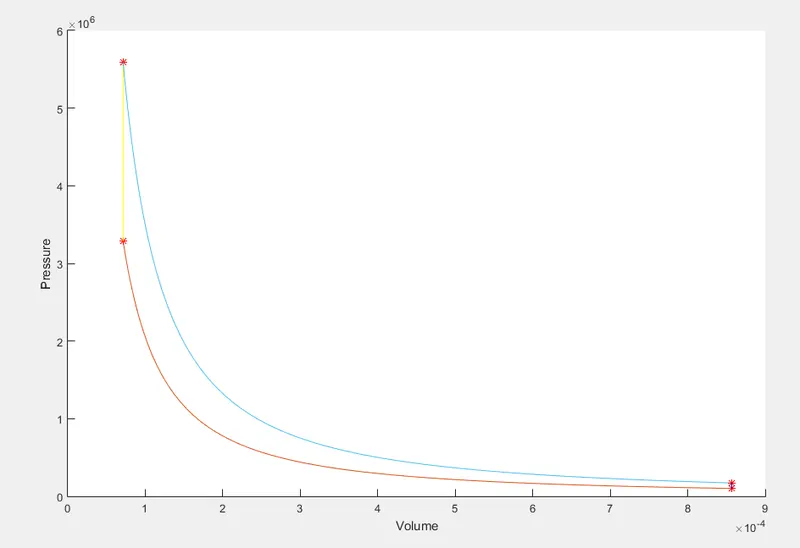
(Plot output generated by Matlab)
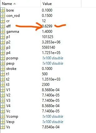
(The value of efficiency is marked in the figure above which shows workspace of he code)
ERROR ENCOUNTERED :
- I used the ideal gas equations wrong by confusion and typed t2=p1V1t1/p2V2 instead of the correct p2V2t1/p1V1
- I used the formula for efficiency wrong as i used `eta`=1-1/cr^`gamma` instead of 1-1/cr^`gamma`-1, i got to know about the error as i got eff of 0.9 by using wrong formula and i realised something is wrong as eff cant be this much high.
REFERENCES :
- https://study.com/academy/answer/compare-the-otto-cycle-and-the-diesel-cycle-a-draw-the-p-v-t-s-and-t-v-diagrams-b-discuss-the-similarity-and-the-difference-about-their-thermal-efficiencies-c-based-on-these-two-cycles-draw.html)
- https://rajeshsky.webs.com/ENGINES%20MATERIALS.pdf)
- Nag,P.K. , "Basic Applied Thermodynamics",2002,McGraw Hill Publishing Limited.