#9 Thermal Management of battery
1)Prepare a report summarizing thermal management techniques for electric car battery pack
To operate an electric vehicle with a particularly high level of efficiency, it is necessary to maintain an optimal temperature range for the battery and other electronic systems. This requires a sophisticated thermal management system
Refrigerant-based system (or direct battery cooling)
The circuit of the refrigerant-based system consists of the main components: Condenser, evaporator and battery unit (battery cells, cooling plate and electric auxiliary heater). It is supplied by the refrigerant circuit of the air-conditioning system and controlled separately via valves and temperature sensors. The functions of the individual components are described in the explanation for the illustration of the coolant and refrigerant-based system
Phase changing material (PCM)
A phase changing material used as a conductor that will transition between solid and liquid. When the battery gets too hot, the PCM will absorb the heat.
Aluminium Foil heat transfer
Some manufacturers are placing a aluminium foil surrounding each cell which will conduct the heat from inside the battery pack to outside.
2)Create a simple simscape model with a battery and show the temparature dependance in the performance.Also connect a resistor load of 10 Ohm
 |
This block creates a physical signal constant |
 |
Controlled current source block will create a output current corresponding to the input physical signal. |
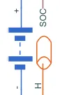 |
This block models a battery based on tabulated characteristics as functions of state of charge (SOC) and optional temperature (T). |
 |
This block represents an ideal energy source in a thermal network that can maintain a constant absolute temperature at the port regardless of the heat flow rate. |
 |
This block models heat transfer in a thermal network by convection due to fluid motion. The rate of heat transfer is proportional to the temperature difference, heat transfer coefficient, and surface area in contact with the fluid. |
 |
This block measures temperature in a thermal network. There is no heat flow through the sensor. The physical signal port T reports the temperature difference across the sensor. The measurement is positive when the temperature at port A is greater than the temperature at port B. |
 |
This block represents a reference point in a thermal network where the temperature is equal to absolute zero. |
 |
The voltage-current (V-I) relationship for a linear resistor is V=I*R, where R is the constant resistance in ohms. |
 |
Electrical reference port. A model must contain at least one electrical reference port (electrical ground). |
 |
Scope block used to plot the obtained results with respect to the simulation time. |
The model explanation:
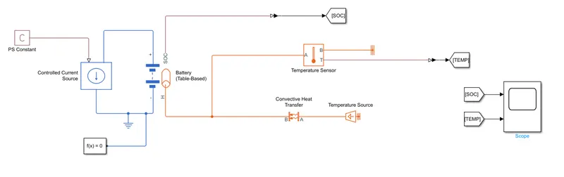
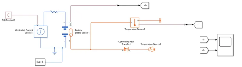
To create a thermal model of the battery i have used a table based battery block with instrumented thermal port. The capacity of the battery is 4.2Ah and the temperature of battery is 298.15K. The input to the battery is given by the controlled current source using a PS constant block.
Discharge current of 2.1A (0.5C) is used in PS constant block.
A temperature source at 293.15K along with convection heat transfer is connected to the thermal port of the battery. Surface area in contact fluid used here is 1m2. The change in temperature is monitored using temperature sensor which is connected to scope to plot the results.
The SOC is also plotted using scope.
In second case, a resistor of 10ohms is connected in series with a battery to observe the effect on SOC and temperature.
Results
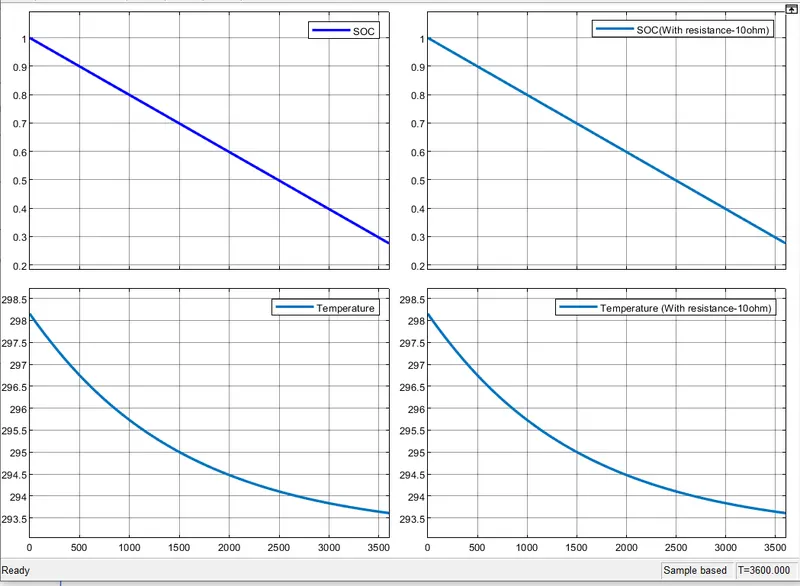
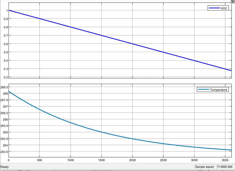
When the battery is discharged at 0.5C rate, the temperature of the battery is continously decreasing from 298.15K to 293.15K.
The State of charge is also start decreasing from 1 and at the end of 1hour(3600s) the soc is less than 0.3.
When a resistor of 10ohms is connected in series, there is no change in the behaviour of the soc and temperature. This might be because a low value of resistance is used.
Area of contact with fluid is 10m2.
When the area of contact with fluid is changed to 1m2 and the change in behaviour of the temperature is shown below.
Your Assets
| Filname | Size | Action |
|---|---|---|
| Thermal…tery.slx | 32.88 KB |