#9 Induction Motor-2
Question
- Discuss about the equivalent circuit network of induction motor MATLAB model.
- 3 phase, 50 Hz induction motor, represented by equivalent circuit constants X1 = X2 = 0.1 ohm and R1 = R2 = 0.2 ohm is operated at half of rated voltage and frequency. Calculate the ratio of starting torque at half voltage & frequency to rated values.
- Make a comparison of square wave inverter output voltage with sine modulated one.
Use the "INSERT CODE SAMPLE" option to paste your code.
SUBMISSION RULES
Use the "INSERT CODE SAMPLE" option to paste your code and attach screenshots of the output. 10 points will be reduced for not doing so. Just showing the code and not explaing the results. 20 points will be reduced if this happens.
If your program or model fails to compile then you will score 0, in that particular challenge. This is applicable only for challenges where you are asked to code or submit the model files
Create a zip file with all the necessary .m files model files etc. in google drive and them as a single zip file.
Copying code from others - If you copy code from others, your score will be 0. If you copy from others on more than 1 assignments your challenges will no longer be graded. You can still access the course but your challenges will not be graded.
If you have attached links to images or videos, make sure that they work before you hit submit. At the time of grading broken links will not be taken into account.
Once graded future submissions will not be valid
Make sure you provide open links while attaching Google Sheets file
Make sure you follow the constraints given in the question, violating them will results in 0 marks.
GENERAL INSTRUCTIONS:
The codes, plots, images, GIFs, and videos should be submitted only through the answer box.
Use the Google Drive to share only the cad models or other answers which couldn't be done through the answer box.
NOTE:
Violating the above instructions will lead to ZERO marks.
Link sharing should be enabled while sharing the Google Drive link, else the challenge will be awarded ZERO marks.
Your Answers
1.Discuss about the equivalent circuit network of induction motor MATLAB model.
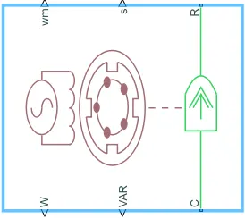
Induction motor with AC supply Block:
Description
The Simplified Induction Motor block represents the electrical and torque characteristics of an induction motor powered by an ideal AC supply. The following figure shows the equivalent circuit model of the Simplified Induction Motor block.
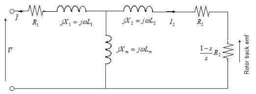
In the figure:
-
R1 is the stator resistance.
-
R2 is the rotor resistance with respect to the stator.
-
L1 is the stator inductance.
-
L2 is the rotor inductance with respect to the stator.
-
Lm is magnetizing inductance.
-
s is the rotor slip.
-
‾‾V and ‾I are the sinusoidal supply voltage and current phasors.
Rotor slip s is defined in terms of the mechanical rotational speed ωm, the number of pole pairs p, and the electrical supply frequency ω by
s=1−pωmω
This means that the slip is one when starting, and zero when running synchronously with the supply frequency.
For an n-phase induction motor the torque-speed relationship is given by:
T=npR2sωVrms2(R1+R2+1−ssR2)2+(X1+X2)2
where:
-
Vrms is the line-neutral supply voltage for a star-configuration induction motor, and the line-to-line voltage for a delta-configuration induction motor.
-
n is the number of phases.
You can parameterize this block in terms of the preceding equivalent circuit model parameters or in terms of the motor ratings the block uses to derive these parameters.
This block produces a positive torque acting from the mechanical C to R ports.
Thermal Ports
The block has two optional thermal ports, one per winding, hidden by default. To expose the thermal ports, right-click the block in your model, and then from the context menu select Simscape > Block choices > Show thermal port. This action displays the thermal ports on the block icon, and exposes the Temperature Dependence and Thermal Port parameters. These parameters are described further on this reference page.
Use the thermal ports to simulate the effects of copper resistance losses that convert electrical power to heat. For more information on using thermal ports in actuator blocks,
Assumptions and Limitations
-
The block does not model the starting mechanism for a single-phase induction motor.
-
When you parameterize the block by motor ratings, the block derives the equivalent circuit model parameters by assuming that the effect of the magnetizing inductance Lm is negligible, and the magnetizing inductance is not included in the simulated component.
Equivalent Circuit of an Induction Motor
The Equivalent Circuit of an Induction motor enables the performance characteristics which are evaluated for steady-state conditions. An induction motor is based on the principle of induction of voltages and currents. The voltage and current are induced in the rotor circuit from the stator circuit for the operation. The equivalent circuit of an induction motor is similar to that of the transformer.
Stator Circuit Model
The stator circuit model of an induction motor consists of a stator phase winding resistance R1, stator phase winding leakage reactance X1 as shown in the circuit diagram below:
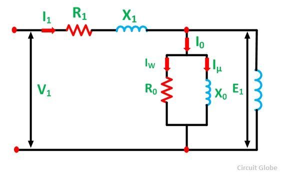
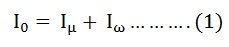
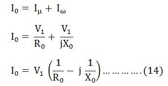
The no-load current I0 is simulated by a pure inductive reactor X0 taking the magnetizing component Iµ and a non-inductive resistor R0 carrying the core loss current Iω. Thus,
The total magnetizing current I0 is considerably larger in the case of the induction motor as compared to that of a transformer. This is because of the higher reluctance caused by the air gap of the induction motor. As we know that, in a transformer, the no-load current varies from 2 to 5% of the rated current, whereas in an induction motor the no-load current is about 25 to 40% of the rated current depending upon the size of the motor. The value of the magnetizing reactance X0 is also very small in an induction motor.
Rotor Circuit Model
When a three phase supply is applied to the stator windings, a voltage is induced in the rotor windings of the machine. The greater will be the relative motion of the rotor and the stator magnetic fields, the greater will be the resulting rotor voltage. The largest relative motion occurs at the standstill condition. This condition is also known as the locked rotor or blocked rotor condition. If the induced rotor voltage at this condition is E20 then the induced voltage at any slip is given by the equation shown below:
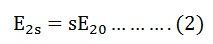
The rotor resistance is constant and is independent of the slip. The reactance of the induction motor depends upon the inductance of the rotor and the frequency of the voltage and current in the rotor.
If L2 is the inductance of the rotor, the rotor reactance is given by the equation shown below:
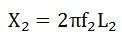
But, as we know,

Therefore,
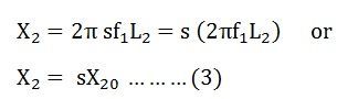
Where X20 is the standstill reactance of the rotor.
The rotor circuit is shown below:
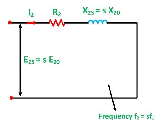
The rotor impedance is given by the equation below:
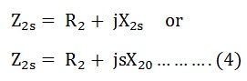
The rotor current per phase is given by the equation shown below:
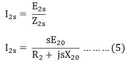
Here, I2 is the slip frequency current produced by a slip frequency induced voltage sE20 acting in the rotor circuit having an impedance per phase of (R2 + jsX20).
Now, dividing the equation (5) by slip s we get the following equation:
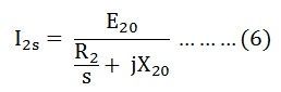
The R2 is a constant resistance and a variable leakage reactance sX20. Similarly, the rotor circuit shown below has a constant leakage reactance X20 and a variable resistance R2/s.
Equation (6) above explains the secondary circuit of an imaginary transformer, with a constant voltage ratio and with the same frequency of both sides. This imaginary stationary rotor carries the same current as of the actual rotating rotor. This makes it possible to transfer the secondary rotor impedance to the primary stator side.
Approximate Equivalent Circuit of an Induction Motor
The equivalent circuit is further simplified by shifting the shunt impedance branches R0 and X0 to the input terminals as shown in the circuit diagram below:
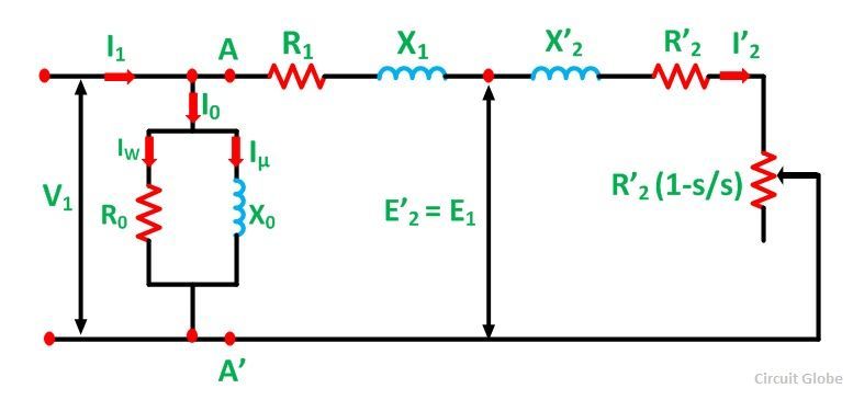
The approximate circuit is based on the assumption that V1 = E1 = E’2. In the above circuit, the only component that depends on the slip is the resistance. All the other quantities are constant. The following equations can be written at any given slip s is as follows:
Impedance beyond AA’ is given as:
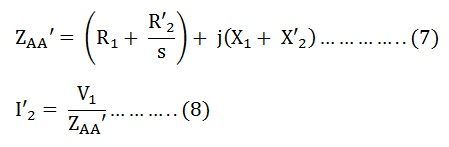
Putting the value of ZAA’ from the equation (7) in equation (8) we get,
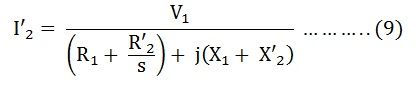
Therefore,
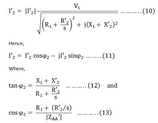
No-load current I0 is
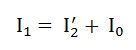
The total stator current is given by the equation shown below:
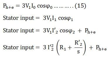
Total core losses are given by the equation shown below:
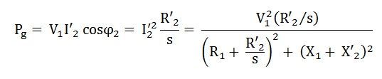
The air gap power per phase is given as:
The developed torque is given by the equation shown below:
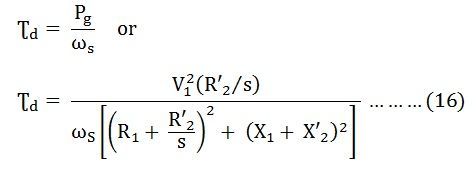
The above equation is the torque equation of an induction motor. The approximate equivalent circuit model is the standard for all performance calculations of an induction motor.
2. 3phase, 50 Hz induction motor, represented by equivalent circuit constants X1 = X2 = 0.1 ohm and R1 = R2 = 0.2 ohm is operated at half of rated voltage and frequency. Calculate the ratio of starting torque at half voltage & frequency to rated values.
Using Kirchoffs law, the established Torque equation is
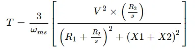
where ω_ms- Synchronous speed of the motor.
R1-Stator Resistance =0.2ohm
R2-Rotor Resistance = 0.2ohm
X1-Stator Inductance = 0.1ohm
X2-Rotor Inductance = 0.1ohm
S-Slip
for starting torque S=1
For synchronous speed of the motor
ω_ms= 120*f/P
f=frequency supplied
P-No.of. poles
For full rated frequency (50Hz) for half rated frequency (25HZ)
ω_ms1= 120*50/P ω_ms2=120*25/P
ω_ms1=6000/P ω_ms2=3000/P
ω_ms1=2*ω_ms2
Now for starting torque by appling above known values in the torque equation,
T=3/ω_ms[(V^2*0.2) / ((0.2+0.2)^2+(0.1+0.1)^2))]
For full rated voltage (V) For Half rate Voltage (V/2)
T1=3/ω_ms1[(V^2*0.2)/ (0.20)] T2=3/ω_ms2[(V/2)^2*0.20)/0.20]
T1=3/(2*ω_ms2) [v^2] T2=3/ω_ms2[V^2/4]
T1=1.5V^2/ω_ms2 T2=0.75 V^2/ω_ms2
Therefore the ratio of starting torque will be
T2/T1= 0.75V^2/ω_ms2 * ω_ms2/1.5V^2
T2/T1= 0.5 =1/2
Therefore the ratio of starting torque will be T2=0.5T1
3.Make a comparison of square wave inverter output voltage with sine modulated one.
Sine Wave Inverter:
sine wave inverters transform direct current (DC) from a battery into an alternating current (AC). The AC power can then be used to run appliances, lamps and light strips, compressors and other devices that cannot run directly on battery power.
The concept of a sine wave inverter is relatively straightforward, but things can get a bit more complicated when you start to browse through all the different sine wave inverters out there. You’ll find two main types of inverters: pure sine wave inverters and modified sine wave inverters(square wave inverters).
Pure sine wave inverters are typically the most expensive of the bunch. That’s because they produce AC power that most closely matches an actual sine wave, or the power provided by wall outlets. A pure sine wave is a steady, continuous wave that provides a smooth, periodic oscillation.
Pure sine wave inverters are at the top of the list of functionality, with the ability to run any and all equipment designed to work on a pure sign wave. All devices you power with a pure sine wave inverter will work to their full specifications.
Devices that require pure sine wave inverters include:
- Appliances with AC motors, such as refrigerators, compressors or microwaves
- Other devices, like bread makers, certain battery chargers and light dimmers
- Audio and video equipment, satellite systems
- Certain medical equipment, such as many CPAP devices for sleep apnea and oxygen concentrators
Pure sine wave inverters cover all bases, ensuring everything you power with it will be running to its full functionality and capacity.
Square wave inverters:
Square wave inverters are usually the least expensive sine wave inverters, as they create a type of sine wave that’s easiest to produce. Their polarity rapidly switches from positive to negative, which creates a waveform that is more like a square wave than the rounded arc found with the pure sine inverters.
Most equipment may still work fine with a modified sine wave inverter, although there are certain exceptions. Some devices will run at reduced power or risk damage with a modified sine wave inverter, while others won’t run at all. Check your manufacturer’s guide for specifics, especially for laptops.
Devices you don’t want to try to run on modified sine wave inverters include:
- Motors, along with devices and appliances with motors, like fans, refrigerators, microwaves. The lower efficiency of the modified sine inverter will cause the motors to require too much power to function, overheating or damaging the unit.
- Any appliance with digital clocks or electric timers will not operate properly, with the clocks and timing devices often getting their power from the peak of the sine wave. The flattened wave pattern doesn’t provide the peak they need, and it can cause malfunction.
- The same type of issue arises with equipment that use electric temperature controls or variable speeds. A variable speed drill, for instance, may only run on high or low speeds with a modified sine inverter, rather than all the speeds in between.
- Certain fluorescent lighting devices will not operate as brightly, and others may make annoying buzzing or humming noises.
Unless you have equipment that specifically falls into the exceptions, modified sine wave inverters can provide a cost-effective option for many devices. They’re also the most common and popular inverters on the market.
| List of Features | Square Wave Inverter | Sine Wave Inverter |
|
Supported Appliances |
Square wave inverters are usually used to support motors alone. |
Sine wave inverters are used to support household appliances such as refrigerators ovens, computers, laptops, etc. |
|
Overall Safety Level |
Square wave inverters are less reliable and also unsafe to use for appliances. | Sine inverters are highly safe to use. |
|
Noise Interference |
Square wave inverters produce a very loud noise when used. | Sine wave inverters produce normal sound only. |
|
Cost |
Square wave inverters are less expensive than Sine wave inverters. | Sine wave inverters are more expensive than Square wave inverters. |