#8 Multi cell Battery Pack
Question
1. How weakest cell limits the usable capacity of the battery pack?
2. Explain the cell balancing techiniques with relevant figures.
Your Answers
How weakest cell limits the usable capacity of the battery pack?
consider a four cells with different state of charge are in series/parallel to power our electronic device.
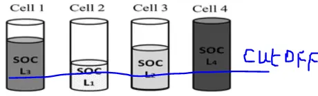
When we start discharging the battery the cell-2 which is in Low SOC will reach its cut-off voltage in short period of time(for example: 2 hrs). The other cells which are at high SOC are having more capacity still left to deliver. In this case, we can discharge the battery pack only upto 2hrs becuase it is absolutely not desirable to discharge a battery/cell beyond cut-off voltage(such a case is called abusing the battery pack). The cell-2 is the weakest cell which determines the usable capacity of the battery pack.
Similarly while charging the battery pack, the cell-4 which is in high SOC will get fully discharged in short period of time(for example: 2 hrs). The other cells like cell-2 which is deeply discharged will take more time to get fully charged. If we continue charging then cell-4 will get overcharged which is also called abusing the battery, so we can only charge for 2hrs which is also determined by the weakest cell(Cell-4 incase of charging).
The solution to such a problem is called cell balancing.
Explain the cell balancing techiniques with relevant figures.
Cell balancing is a technique that improves battery life by maximizing the capacity of a battery pack with multiple cells in series, ensuring that all of its energy is available for use. A cell balancer or regulator is a functionality in a battery management system that performs cell balancing often found in lithium-ion battery packs electric vehicles and ESS applications
Types of cell balancing
- Active balancing
- Passive balancing
- Lossless Cell Balancing
- Redox Shuttle
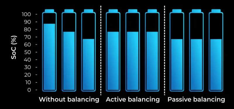
1)Active Cell Balancing
An active cell balancer generally transfers energy from one cell to another. That is from high voltage/ high SoC to a cell with a lower SoC. The purpose of an active balancer is that if you have a pack of cells with lower capacity, you can extend the life or the SoC that you have on the pack by moving energy from one cell in the pack with more energy than the other cell.
Instead of wasting all that energy as heat, an active cell balancer efficiently balances cells with tiny converter circuits that pass energy from the highest voltage cells to the lowest voltage cells. There are two different categories of active cell balancing methods: charge shuttling and energy converters. Charge shuttling is used to actively transport charges from one cell to another to achieve equal cell voltage. Energy converters use transformers and inductors to move energy among the cells of a battery pack.
Other active cell balancing circuits are typically based on capacitors, inductors or transformers, and power electronics interface. These entail:
Based on capacitors
- Single capacitors – this method is simple because it uses a single capacitor regardless of the number of cells connected in the battery. However, this method requires a large number of switches and intelligent control of the switches.
- Multiple capacitors – this method with multiple capacitors connected to each battery transfers unequal cell energy by multiple capacitors. It does not require a voltage sensor or closed-loop control.
Based on inductors or transformers
- Single/ multiple inductors – a cell balancing circuit with a single inductor has a small volume and low cost while multiple inductors have fast balancing speed and decent cell balancing efficiency.
- Single transformer – this method has a fast balancing speed with low magnetic losses.
- Multiple transformers – this cell balancer has a fast equalizing speed. However, it requires an expensive and complex circuit that prevents the transformer from being flooded.
Based on Power Electronics Interface
- Flyback/ forward converter – the energy of a high voltage cell is stored in the transformer. This cell balancer has high reliability.
- Full-bridge converter – this cell balancer has fast equalization speed and high efficiency.
Active balancers are capable of pushing a lot of current from one cell to another.
Advantages of Active Cell Balancing:
- It improves capacity usage. It performs great when you have different cell capacities in a series.
- It increases energy efficiency. It saves energy instead of burning the excess energy in a cell by transferring the excess energy to a lower energy cell.
- Lifetime extension. It improves the life expectancy of a cell.
- Fast balancing.
Disadvantages of Active Cell Balancing:
- When you transfer energy from one cell to another, approximately 10-20% of the energy is lost.
- The charge could be transferred only from higher cell to lower cell.
- Although an active cell balancer has high energy efficiency, its control algorithm may be complex and its production cost is expensive because each cell should be connected with an additional power electronics interface.
2)Passive Cell Balancing
A passive system potentially burns off excess energy from the high cells through a resistive element until the charge matches the lower energy cells in the pack. If you have cells packed in series and you notice that some of the cells have higher energy than the other lower energy cells, you can balance the cells in burning energy of the top cells simply by attaching a resistor to the cells which releases the energy into heat thereby equalizing the cell energy of the battery pack.
Initially, you burn off the excess energy until you have balanced cells. Passive cell balancing allows all cells to appear to have the same capacity. There are two different categories of passive cell balancing method: fixed shunting resistor and switching shunting resistor. A fixed shunting resistor circuit is usually connected to the fixed shunting to prevent it from being overcharged. With the help of the resistors, the passive balancing circuit can control the limit value of each cell voltage without damaging the cells. Energy consumed by these resistors for balancing a battery may result in thermal losses in the BMS. This, therefore, proves the fixed shunting resistor method to be an inefficient cell equalizing circuit.
The switch shunting resistor cell balancing circuit is currently the most common method in cell equalizing. This method has a continuous mode and a sensing mode, where the continuous mode all switches are controlled to be turned on or off at the same time and in the sensing mode, a real-time voltage sensor is required for each cell. This cell balancing circuit consumes high energy through a balancing resistor. This cell balancing circuit is suitable for a battery system that requires a low current when it is charged or discharged.
Advantages of Passive Cell Balancing:
- You should never have to balance a pack that is working perfectly.
- A cell cannot waste energy that it does not have. As soon as the energy bank is full, that is only when the cell has enough energy to balance.
- It allows all cells to have the same SoC.
- It provides a fairly low-cost method for balancing the cells.
- It can correct for long-term mismatch in self-discharge current from cell to cell.
Disadvantages of Passive Cell Balancing:
- Poor thermal management.
- They do not balance during the full SoC. They only balance through the top of each cell at around 95%. This is because if you have different cell capacities, you are forced to burn off the excess energy.
- Its energy transmission efficiency is usually low. Electrical energy is dissipated as heat in the resistors and the circuit also accounts for switching losses. In other words, it results in a high amount of energy loss.
- It does not improve the run-time of a battery-powered system.
3)Lossless balancing
Lossless balancing is a recently developed method that reduces losses by reducing the hardware components and providing more software control. This also makes the system simpler and more easier to design. This method uses a matrix switching circuit which provides the capability to add or remove a cell from a pack during charging and discharging. A simple matrix switching circuit for eight cells is shown below.
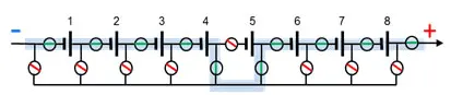
During charging process the cell which is of high voltage will be removed from the pack using the switch arrangements. In the above figure the cell 5 is removed from the pack by using the switches. Consider the red line circles to be open switches and the blue line circle to be closed switches. Thus the rest time of the weaker cells are increased during the charging process so as to balance them during charging. But the charging voltage has to be adjusted accordingly. The same technique can be followed during discharging also.
4) Redox Shuttle
The final method is not for hardware designers but for chemical engineers. In lead acid battery we do not have the problem of cell balancing because when a lead acid battery is overcharged it causes gassing which prevents it from getting over charged. The idea behind Redox shuttle is to try achieving the same effect on lithium cells by altering the chemistry of the electrolyte of the lithium cell. This modified electrolyte should prevent the cell from getting overcharged.
Cell Balancing algorithms
An effective cell balancing technique should combine the hardware to a proper algorithm. There are many algorithms for cell balancing and it depends on the hardware design. But the types can be boiled down to two different sections.
Measuring the Open circuit voltage (OCV)
This is the easy and most commonly followed method. Here the open cell voltages are measured for each cell and cell balancing circuit works to equalize the voltage values of all the cells connected in series. It is simple to measure OCV (Open circuit voltage) and hence the complexity of this algorithm is less.
Measuring Sate of charge (SOC)
In this method the SOC of the cells are balanced. As we already know measuring the SOC of a cell is a complex task since we have to account in the voltage and current value of the cell over a period of time to calculate the value of SOC. This algorithm is complex and used in places where high efficiency and safety is required like in aerospace and space industries.