Modelling of Battery Pack
Question
1.Build a battery pack with 3S4P configuration with generic battery block
a.Configure the batteries as per a Lithium ion battery datasheet
b.Explain your parameters
c.Simulate the model and comment on the results for SOC,voltage ,current in detail
d.Change the configuration to 4S3P and simulate the model
e.Compare the results for both model and give your explanation for the results
Your Answers
Aim:
To build a lithium-ion battery model with 3S4P Configuration and 4S3P Configuration with generic battery Block and compare its results.
The reference data of ANR26650 battery from A123systems is used.
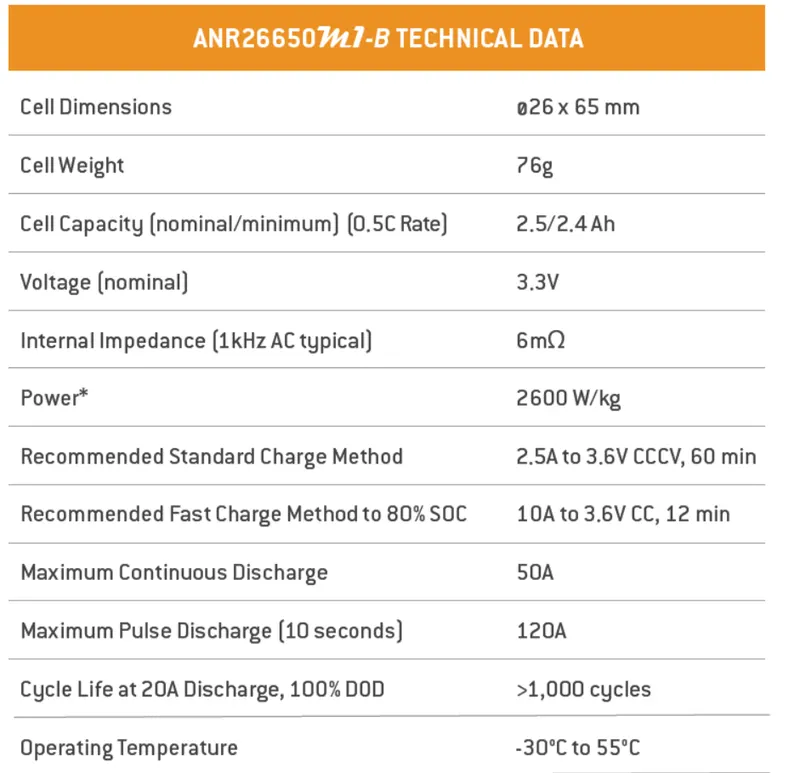
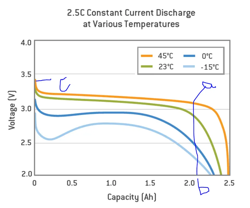
Some data are taken form the discharge characteristics graph given by the manufaturer for accuracy,
where a-Nominal Voltage
b- Capacity at nominal voltage
c- Maximum voltage
The Input Block Parameters as per the datasheet are
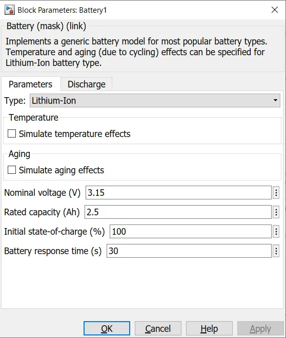
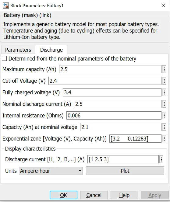
Single cell parameters (used as per datasheet):
Nominal Voltage: 3.15V
Rated capacity: 2.5Ah
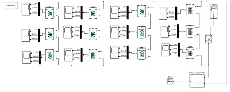
For 3S4P configuration, we have to connect 4 modules of each containing 3cells in series and all the 4 modules are then connected in parallel.
then, Battery parameters
Nominal volatage: 3 * 3.15 =9.45V (In series - voltage addon)
Rated Capacity: 4*2.5= 10Ah (In parallel capacity addon)
Finally we are creating a model for 9.45V 10Ah battery.
The model for 3S4P configuration is
Blocks used in the model:
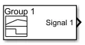 |
Signal builder block used to create a desired input signal with respect to simulation time |
 |
Controlled current source used to create the current signal corresponding to the given physical input signal. |
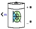 |
The Battery block implements a generic dynamic model that represents most popular types of rechargeable batteries. |
 |
This block represents voltage measurement used to measure the voltage across the connected terminals. |
 |
Scope used to plot the obtained results with respect to the simulation time. |
 |
The powergui block allows you to choose one of the methods to solve the circuit.
|
 |
Demux block used to split vector signals into scalars or smaller vectors. Check 'Bus Selection Mode' to split bus signals. |
Model Explanation :
I have created a own drive cycle kind of input signal using signal builder block for simplicity.
The generated input signal is given to the controlled current source which converts the input physical signal to the corresponding current signals.
The converted current signal is given as a load to the battery pack.
The battery pack is created by connecting 4 modules of each containing 3cells in series and all the 4 modules are then connected in parallel.
A voltage measurement block is connected across the battery pack to measure the voltage of the whole battery pack.
The output signals like state of charge (SOC), Current and Voltage are plotted across each cell using scope.
Results for 3S4P configuration:
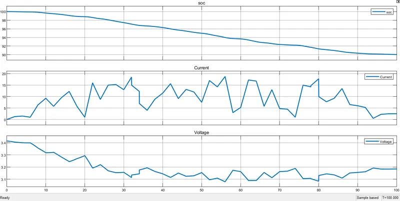
From the graph, the State of charge is decreasing gradually from 100% to 90% correcponding to the load applied.
The second plot shows the current signal which represents the applied load. Inbetween the decrease in current represents the regenerative braking.
The voltage of single cell is around 3.4V intially because we have given initial SOC as 100%, so it takes the maximum voltage at the intial state and starts decreasing gradually correcponding to the load. Whenever there is a decrease in current plot, the voltage increases due to regenerative braking.
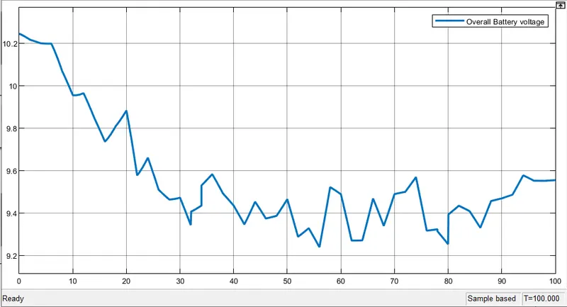
Single cell voltage at fully charged condition (ie, SOC=100%) is 3.4V
Then for the battery 3*3.4 = 10.2V
From the above graph, the Overall voltage of the battery is decreasing from 10.2V to 9.2V with corresponding to the load.
The Model for 4S3P Configuration:
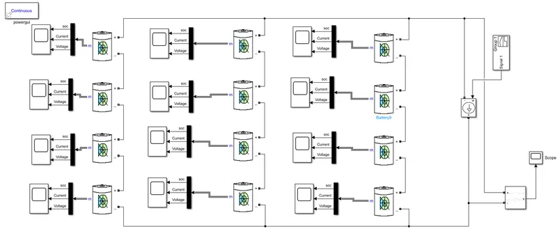
For 4S3P configuration, we have to connect 3 modules of each containing 4cells in series and all the 3 modules are then connected in parallel.
then, Battery parameters
Nominal volatage: 4 * 3.15 =12.6V (In series - voltage addon)
Rated Capacity: 3*2.5= 7.5Ah (In parallel capacity addon)
Finally we are creating a model for 12.6V 7.5Ah battery.
Results for 4S3P configuration:
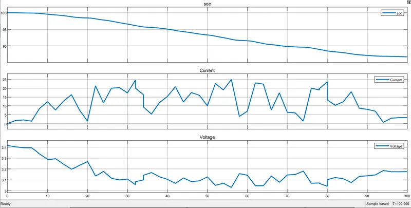
From the graph, the State of charge is decreasing gradually from 100% to around 80% corresponding to the load applied.
The second plot shows the current signal which represents the applied load. Inbetween the decrease in current represents the regenerative braking.
The voltage of single cell is around 3.4V intially because we have given initial SOC as 100%, so it takes the maximum voltage at the intial state and starts decreasing gradually correcponding to the load. Whenever there is a decrease in current plot, the voltage increases due to regenerative braking.
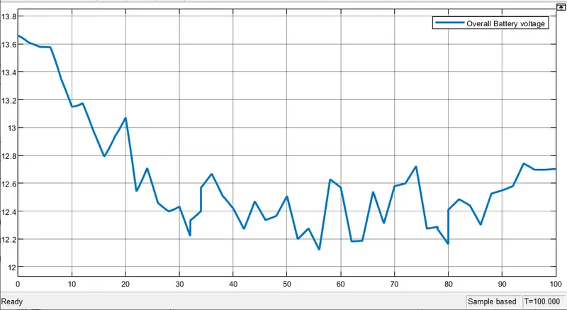
Single cell voltage at fully charged condition (ie, SOC=100%) is 3.4V
Then for the battery 4*3.4 = 13.6V
From the above graph, the Overall voltage of the battery is decreasing from 13.6V to 12.2V with corresponding to the load.
Comparision of results obtained from 3S4P configuration and 4S3P configuration:
3S4P configuration 4S3P configuration
Battery Capacity: 10Ah(high Capacity) 7.5Ah
Battery Nominal Voltage: 9.45V 12.6V (high Voltage)
Single cell Voltage:
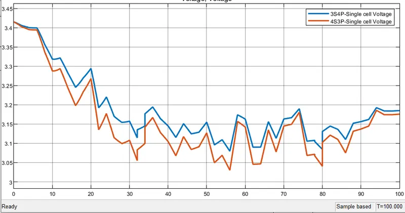
The single cell voltage of 3S4P configuration is slightly higher than the 4S3P configuration because of the higher capacity in the first case.
In both the case same type of battery is used with similar parameters, so that the nominal voltage starts from 3.4V but varies as the simulation proceeds due to the higher capacity in 3S4P configuration.
Overall battery Voltage:
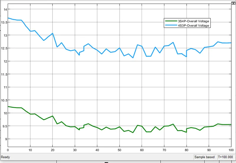
From the graph, the operating voltage range of battery in 3S4P configuration is lower than the 4S3P configuration because the voltage gets add up on series connection, the no of cells connected in series is higher in 4S3P configuration.
State of charge:
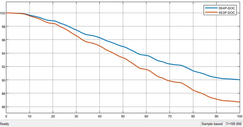
The SOC of 4S3P configuration decreases faster and reaches low value around 87% when compared to 3S4P configuration (90%). This behaviour is happened due to the higher capacity in the 3S4P configuration, so the battery will retain longer period of time.
Load applied to the battery Vs Current taken by single cell:
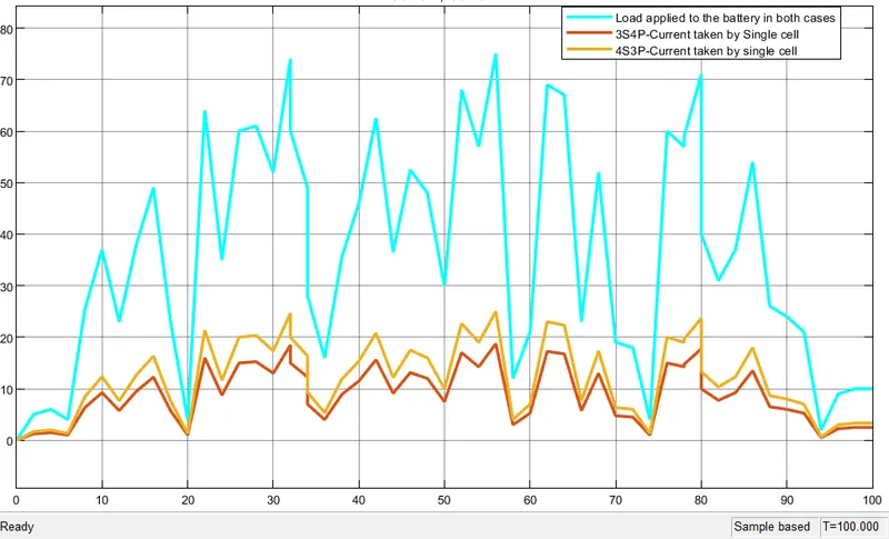
From the above graph, the load applied to both the configuration is same, but the current drawn from each single cell is different in both the configurations because when the battery capacity is higher the load taken from each is low and vice versa.
Since more current is drawn from a single cell in 4S3P configuration, its SOC also decreases rapidly.
Conclusion:
When we have to create a battery pack, first consider the requirement,
if we need a high capacity system, then go for configuration in which no of cells in parallel is more
otherwise if we need a higher voltage system, then go for configuration in which no of cells in series is more.
Your Assets
| Filname | Size | Action |
|---|---|---|
| ThreeSe…odel.slx | 54.32 KB | |
| FourSer…odel.slx | 39.33 KB |