#5 Fuel cell powered model
Fuel Cell:
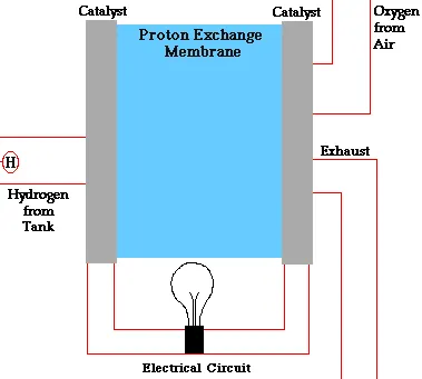
A fuel cell uses the chemical energy of hydrogen or other fuels to cleanly and efficiently produce electricity. If hydrogen is the fuel, the only products are electricity, water, and heat. Fuel cells are unique in terms of the variety of their potential applications; they can use a wide range of fuels and feedstocks and can provide power for systems as large as a utility power station and as small as a laptop computer.
How Fuel Cells Work
Fuel cells work like batteries, but they do not run down or need recharging. They produce electricity and heat as long as fuel is supplied. A fuel cell consists of two electrodes—a negative electrode (or anode) and a positive electrode (or cathode)—sandwiched around an electrolyte. A fuel, such as hydrogen, is fed to the anode, and air is fed to the cathode. In a hydrogen fuel cell, a catalyst at the anode separates hydrogen molecules into protons and electrons, which take different paths to the cathode. The electrons go through an external circuit, creating a flow of electricity. The protons migrate through the electrolyte to the cathode, where they unite with oxygen and the electrons to produce water and heat.
Blocks used in the model:
Ramp:

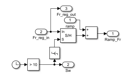
This block represents Ramp which generates a signal that starts at a specified time and value and continuously increasing at specified rate. The Slope, Start time and initial output parameters determine the characteristics of the output signal.
Flow rate selector:
Switch:

Switch block models a switch controlled by an external physical signal. If the external physicl signal PS is greater than the value specified in the threshold then the switch is closed, otherwise, the switch is open.
Saturation:

The Saturation block produces an output signal that is the value of the input signal bounded to the upper and lower saturation values. The upper and lower limits are specified by the parameters Upper limit and Lower limit.
Fuel cell Stack:
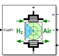
The fuel cell stack implements a generic model parametrized to represent the most popular types of fuel cell stacks of hydrogen and air.
DC/DC Boost converter:
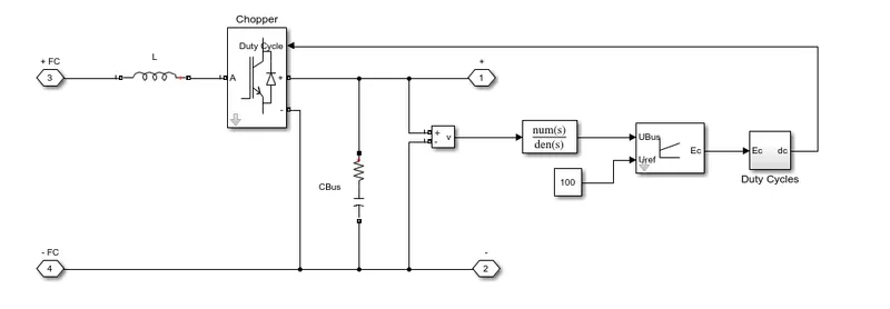
The average value DC/DC converter block represents a controlled average value DC/DC converter. One can program the block as a buck converter, boost conveter or buck-boost converter by providing the duty cycle, The diagram shows the equivalent circuit for the block with a duty cycle as input. The conveter contains a controlled current source and a controlled voltge source. Use the duty cycle , the current refernce or the voltage refernce port as acontrol input converter the electrical energy between the connected components on either side of the converter.
Scope:

This block used to plot the obtained results with respect to the simulation time.
Powergui:
The powergui block allows you to choose one of the methods to solve the circuit.
- Continuous, which uses a variable -step solver from simulink
- Discretization of the electrical system for a solution at fixed time steps
- Continuous or discrete phasor solution
Results:
Flow rate:
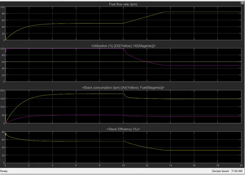
From 0 to 10sec, the flow rate starts increasing and remains constant, untill reaches 50lpm. After 10sec, the flow rate increases upto 95lpm which is attained in 3.5sec.
We are controlling the voltage and current required for the system by changing the flow rate of the hydrigen and oxygen.
Utilization:
As the flow rate is increased to 95lpm, there can be seen a reductiob in the utilization of hydrogen from 100% to 42% whereas the oxygen remains constant at 60%.
Stack consumption(lpm):
We can see in the plot outo 10sec, the oxygen and hydrogen consumption gradually increases and remains constant upto 10sec again after 10sec the hydrogen and oxygen consumption decreases and remains constant.
Stack Efficiency:
At time t=o due to transient state the efficiency first increases and then decreases and renains constant, with the constant stack consumption efficiency again decreases and remains constant after 10 sec.
Voltage and current:
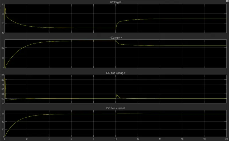
Both voltage and current change its value due to a transient state. We can see the voltage gets down and remains constant, whereas the current goes up gradually and remains constant up to 10sec of simulation. After 10sec with increase in flow rate voltage of the system increases and to compensate for that current value got decreased.
DC bus voltage and current:
The only change in voltage and current can be seen at the transient state of the system. Otherwise there is no chnage in DC bus voltage as DC/DC converter of 100V dc is taken into consideration.