3D Creation of Celing, Roof, Architectural plan, Structural plan, Sectional view, Elevation view and Camera specific view for a house plan using REVIT
3D Creation of Celing, Roof, Architectural plan, Structural plan, Sectional view, Elevation view and Camera specific view for a house plan using Revit
Tools Used:
a. Ceiling
b. Sheet
c. Place a view
d. Levels
e. Grids
f. Roof
g. Place components
h. Load family
i. Property browser
j. Stair
k.Columns
l. Beams
m. Section
n. Elevation
1. Modeling of ceiling
Aim : To model a ceiling above the architectural plan created.
Procedure:
Step 1: Open the project created.
Step 2: Click on first floor in plan view
Step 3: Click on ceiling from the architectural tab.
Step 4: Click on automatic ceiling.
Step 5: Go to level 2 plan view and click on the rooms to create ceiling.
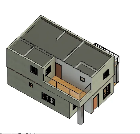
Step 6: Give the offset from level 2 as 3000 in the property browser.
Step 7: Create ceiling above the open terrace by sketching.
Result: Ceiling is modelled above the architectural plan.
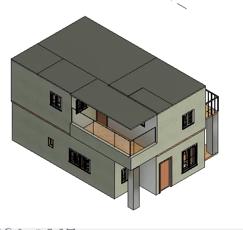
2. Modelling roof above the ceiling
Aim : To create roof above the ceiling and adjusting the roof slope to 10 degree.
Procedure:
Step 1: Go to level 3 floor plan
Step 2: Click on roof tab under architecture tab.
Step 3: Click on pick lines and with draw lines connect the roof line in level 3
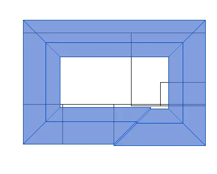
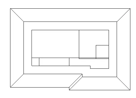
Step 4: Go to 3d view.
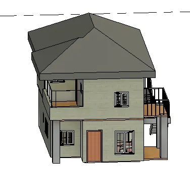
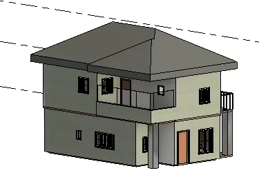
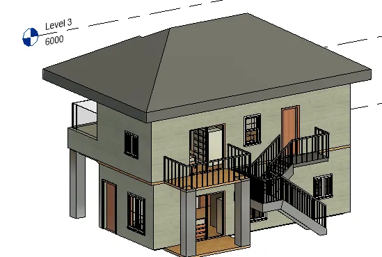
Step 5: Click on the roof in 3d view.
Step6 : We can drag the arrows provided to adust the slopes.
Step 7 : In property browser , we can chnage the roof slope to 10 degree.
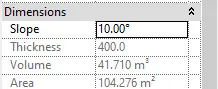
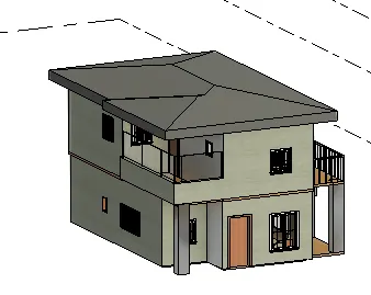
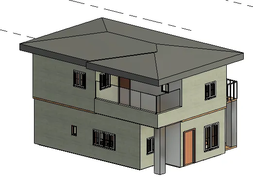
Result : Roof is created above the ceiling and slope is adjusted to 10 degree.
3. Creating architectural and structural plans
Aim : To create plan views for ground floor and first floor levels and seperate them to architectural and structural.
Procedure:
a. Architectural plan - walls , floors and all components inside building.
Step 1: In architetcural tab click on walls and draw the walls.
Step 2: Click on doors and window tab under architectural, and place it wherever required.
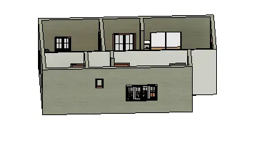
Step 3: Click on floors and click on pick lines and clcik on the outline lines .
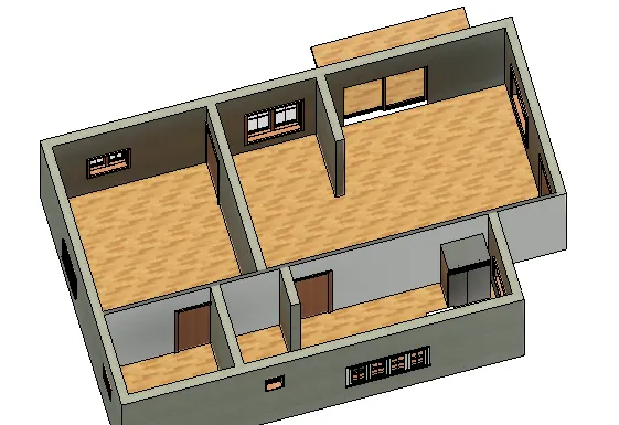
Step 4: Click on place a component under architectural tab and if the componets are present place it or click on load family.
Step 5: Load the components we need to place.
Step 6 : Place sofa and table, chairs, TV , TV stand in the living room
Step 7: Place dinning set in dinning room.
Step 8: Place bed, table ,chair, cabinets in bedroom
Step 9 : Place water closet ,bath tub and sink in the toilet
Step 10: Place hood and hob and cabinets in kitchen
Step 11: Place washing machine and cabinet in the store.
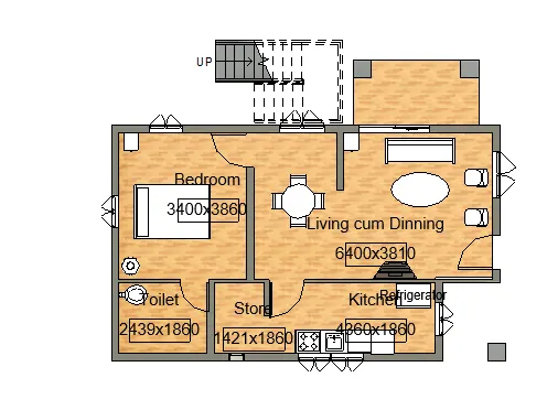
Ground floor plan
Step 12: Similarly by walls create the first floor and by floors create floors.
Step13: Place doors and windows
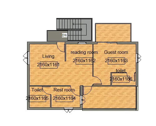
Step14: Place the components
Step15: Sofa set and chairs in living room, bed and cabinets in bedrrom ,reading table and chair and shelves in reading room.
Step16: Water closet and washbasin in toilets.
Step 17: Create stairs for the acess to first floor and pation in bedrooms.
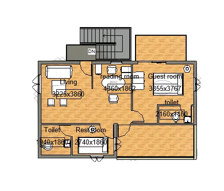
First floor plan
b. Structural plan: Columns and beams
Step 1: Create walls by clickng walls in architectural tab.
Step 2: Create doors and windows .
Step 3: Floor is created by clicking on floor tab and pick lines and seelct the lines.
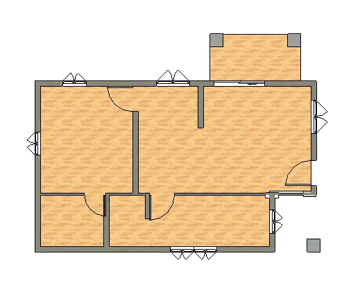
Step 4: Place columns by clicking on column tab under architectural tab.
Step 5: Click on architectural column and place the columns in all corners of the wall and also wherever required.
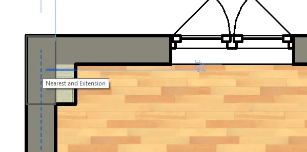
Step 6: As the column is bigger in size, go to edit type , dupilcate and change the size of column- 200x200mm. 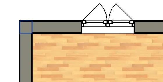
Step 7 : Similarly place the column in all the cornerns and wherever required.
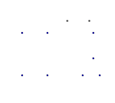
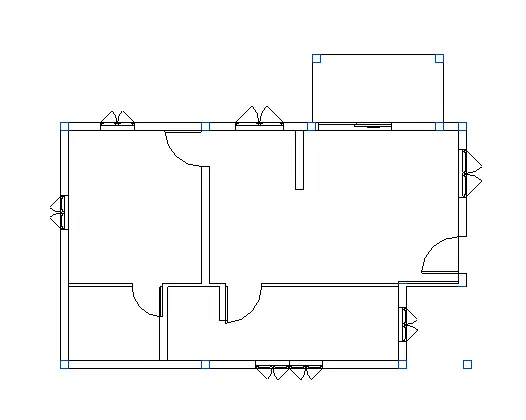 the selected elements are the columns.
Step 8 : Delete the walls and floors.
Step 9 : Select beam from structural tab , and draw beams connecting the column.
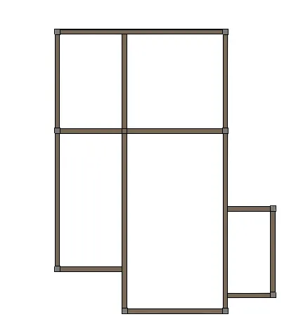
Result: The architectural plan and structural plan has been created.
Ground floor plan
First floor plan
Structural plan
4. Adding dimensions to the architectural and structural plan
Aim : To add dimension using annotate toolbar to the architetcural and structural plan .
Procedure:
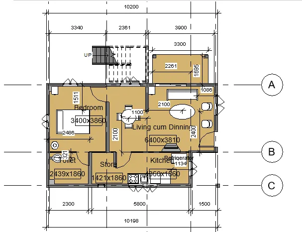
a. Architectural plan - dimensions with respect to the grids
Step 1: The grids are created along walls.
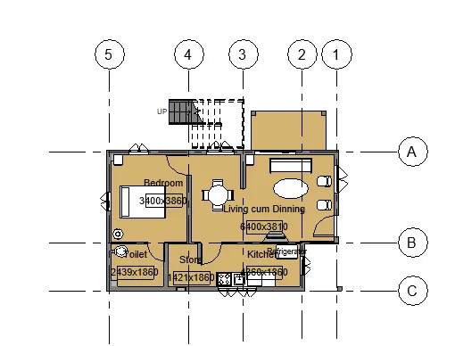
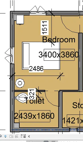
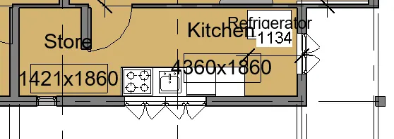
Step 2: Click on annotate tab, select linear dimension.
Step 3: Click on the two walls, to get the distance of the rooms.
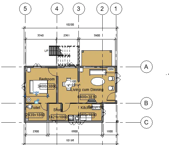
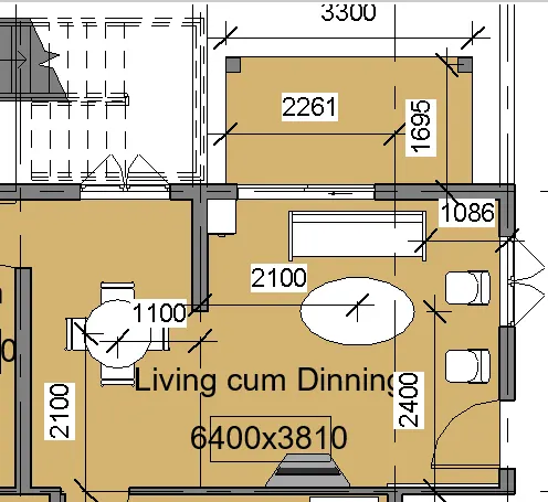
Step 4: Again click on annotate , linear and select the grid points and the components .
Living and dinning:
Bedroom :
Kitchen and store:
b. Structural - dimensions with respect to the grids
Step 1: Create columns on all corners of wall .
Step 2: Create beams connecting the columns.
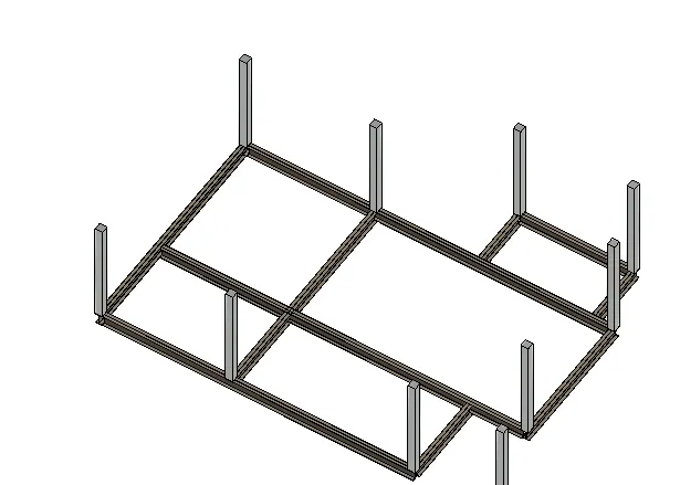
Step 3 : Using grid tab , place the grids at the centre of the column.
Step 4: Use annotate tab , aligned and linear to measure the dimension between the grids, grids and wall.
Step 5 : Measure the dimension from grid and partition walls.
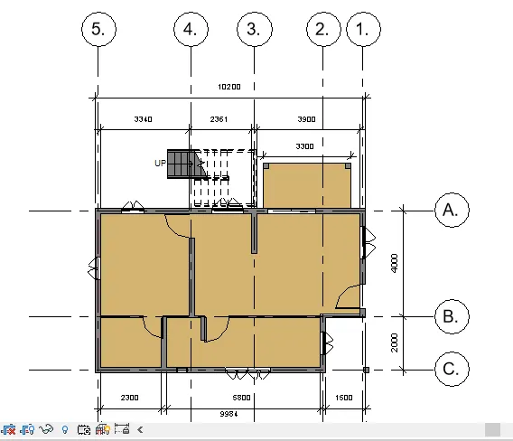
Result : Dimensions with respect to the grids are measured using annotate tool.
5. Creating sheet template
Aim : To create sheet template from the view tab and adjusting the parameters to add views.
Procedure:
Step 1: Click on view tab, select sheet option, seelct A1 metric .
Step 2: If we need more sheet click on load button select title blocks and seelct the sheet we need.
Step 3: A sheet will be created.
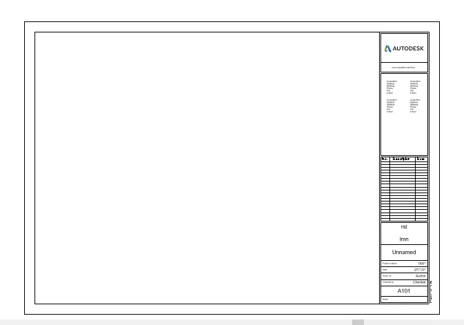
Step 4: We can edit the template by double clicking the letters.
Step 5 : To add views, click on place views under view tab.
Step 6 : Select the views created to place it in the sheet. Click on add view to sheet.
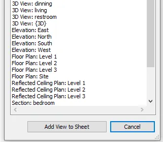
Step 7: When adding if the size is large , click on size crop, select scale and give a value( here 500) and apply.
Step 8 : Click on living and dining views and add them.
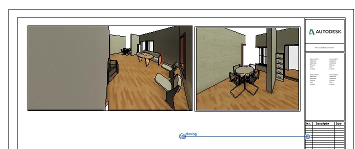
Step 9: Click on 3d view of restorom and3d view of full building. and place in the sheet.
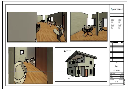
Result:
Sheet template is created and views are placed in the sheet template.
6. Creating elevations:
Aim : Creating elevations views using elevation tab from North , South, East and West.
Procedure:
Step 1: In view tab , click on elevation in level 1 view.
Step 2: Place the view where we need, elevation 1 will be created in the property browser.
Step 3: Click on elevation 1 to see the view.
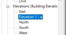
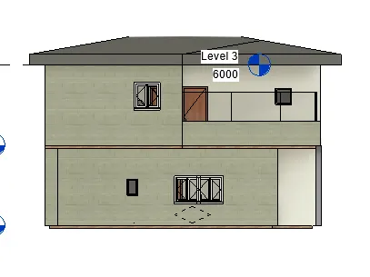
Step 4 : Similarly place the elevation blocks in North, South, East and West and rename it espectively.
Step 5: Click on elevation tab from the project browser.
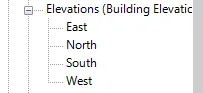
Step 6 : Expand the elevation tab , we can see different elevations of North , East , West and South.
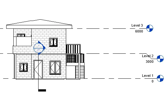
Step 7: Click on East view.
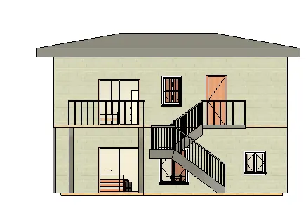
Step 8: Click on North view.
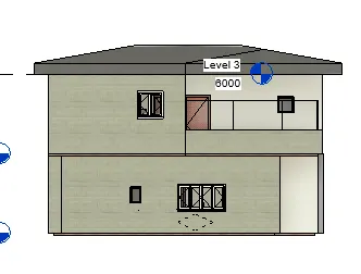
Step 9: Click on South view.
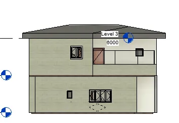
Step 10 : Click on West view.
Step11 : To create more views, click on view -elevation and place the elevation blocks to where we need the view.
Result : North , South , East and West elevations are created using elevation tab
North
South
East
West
7. Section cut through each room cutting longitudinally and transversely.
Aim : To create section through each room creating sections longitudinally and transversely.
Procedure:
Step 1: Click on section tab from view tab , draw the section through the living and dinning longitudinally.
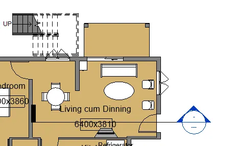
Step 2: Click on section view from the property browser , we can see the view.
Step 3: Click on section tab , from view tab and place the section through the bedroom longitudinally.
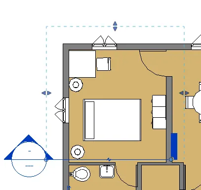
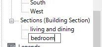
Step 4 : Click on section view and select the created section from property browser, we can change the name by right clicking and rename it to bedroom
Step 5: Click on the bedroom view from the section tab.
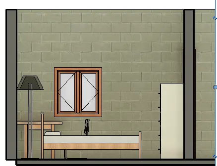
Step 6: Click on section from the view tab . and draw the section transversily in the restroom.
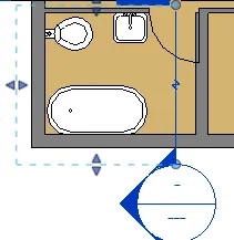
Step 7: Click on section tab from property browserand rename the section to restroom.
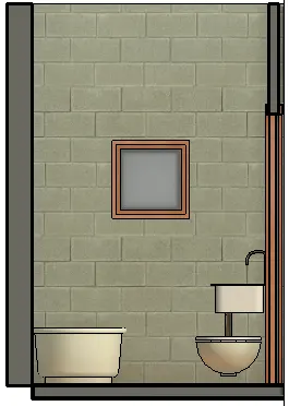
Step 8: Click on section view from view tab, and draw section line through transverese direction in kitchen.
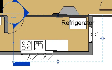
Step 9 : Click on section from the property browser and rename it to kitchen and select the view.
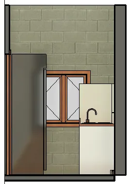
Step 10: Create a longitudinal section for the kitchen
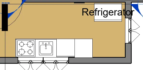
Step 11: Select the view from section under property tab.
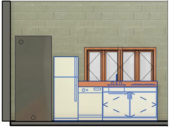
Step 12: Click on section from view tab and craete a transverse section fro the store room.
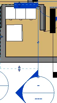
Step 13: Go to section under property tab and change the name to store and select the view.
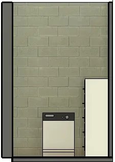
Result:
Section view are created for:
a. Living and dinning room
b. Bedroom
c. Restroom
d. Kitchen
e. Store room
8. Classifying different views
Aim : To classify different views like plan views, section views and elevation views and docment it in project browser
Procedure:
Step 1: In the property browser we can see all the views are visible.
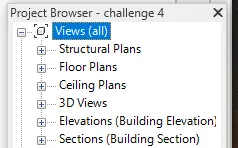
Step 2: Click on each of the tab to expand it , so that we can see the plans, elevations and section view created.
Step3: For plan view , click on the floor plans and expand it.
Step 4: We can see that level 1, level2, level 3 which are created are visible.
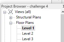
Step 5: Select on each level to see the floorplan of that level. -level 2 created at 3000mm and level 3 at 6000mm.
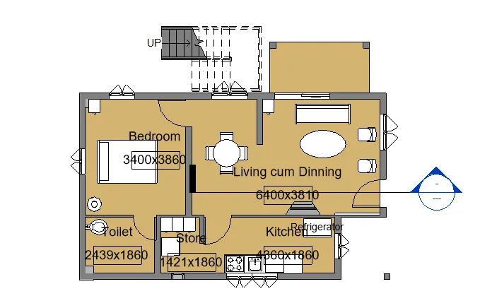
Step 6: Select level 2 so that we can see the plan view of first floor level.
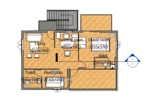
Step 7: Click on elevation in property browser , expand it and we can see that different elevations views are there.
Step 8 : Click on East to see the east elevation view.
Step 9 : Click on North elevation .
Step 10: Click on South elevation.
Step 11: Click on West
Step 12: Click on section , to expand the views.
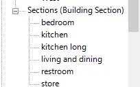
Step 13: Select bedroom view.

Step 14: Seelct living and dinning
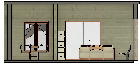
Step 15: Select kitchen and store
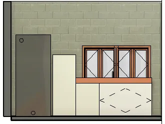
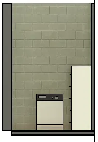
Step 16: Select restroom.
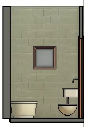
Result:
Views are classified and are documented in the project browser.
9. Creating multiple sheet from sheet templates.
Aim : Creating multiple sheets using sheet template
a. A101- Ground Floor Architectural Plan
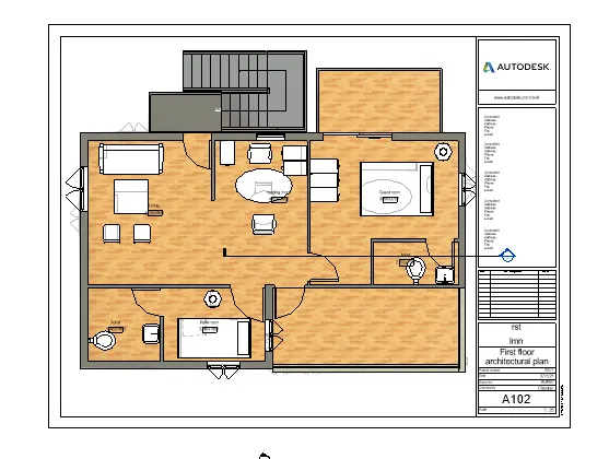
b. A102 - First Floor Architectural Plan
c. A103- Roof Plan
d. S101- Ground Floor Structural Plan
e. S102- First Fllor Structural plan
f. S103- Roofframing Plan
g. A201- North -South elevations
h. A202- East West elevations
i. A203-A206 Sections
Procedure:
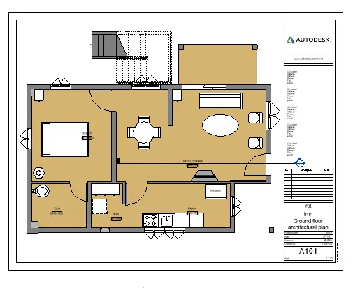
a. A101 - Ground floor architectural plan
Step 1: Click on create sheet from the view tab .
Step 2: Select the sheet , or load another if needed.
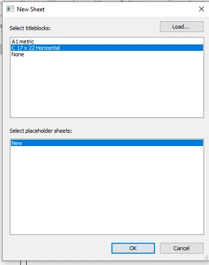
Step 3 : The sheet created will be visible in the project browser , renma ethe sheet name as A101- Ground floor architectural plan
Step 4: Click on place view in the view tab , a dilaogue box appears.
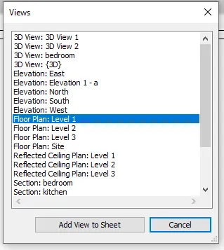
Step 5 : Select floor plan level 1 , click on add view to sheet.
b. A102- First Floor architectural plan
Step 6 : Create another sheet from view tab - new sheet.
Step 7 : Rename it to A 102- First floor architectural plan.
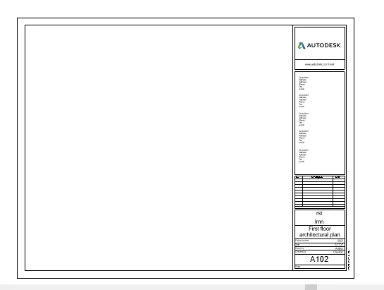
Step 8 : Click on place view under view tab
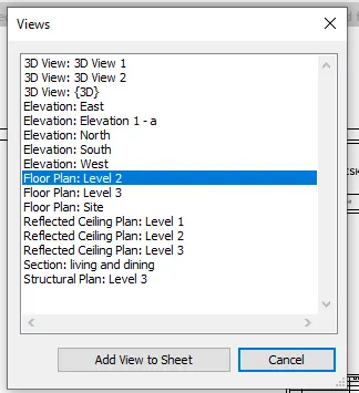
Step 9 : Select floor plan level 2, add view to sheet.
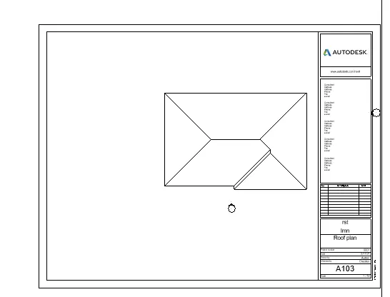
c. A103- Roof plan
Step 10: Click on create sheet from the view tab.
Step 11: Rename the sheet name to A103-Roof plan
Step 12: Select place view and place ceiling plan.
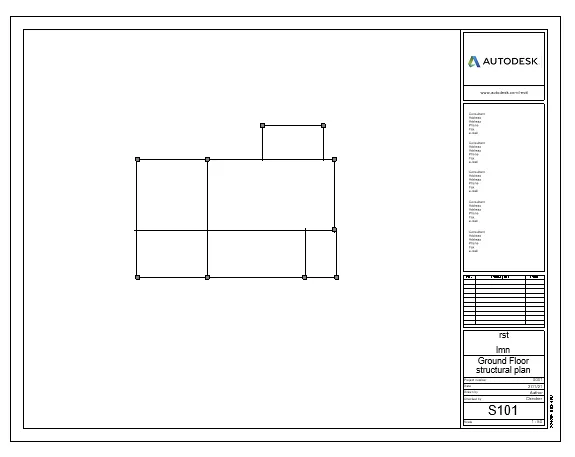
d. S101- Ground Floor Structural Plan
Step 13: Select sheet from view tab
Step 14: Rename it to S101- Ground Floor structural plan.
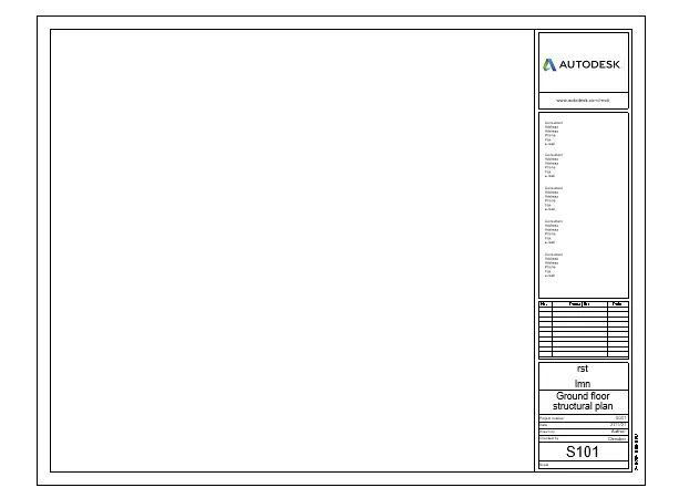
Step 15 : Click on place view from the view tab , and place the structural plan.
e. S102- First floor structural Plan
Step 16: Select the created column and change the top constrain to level 3 with base constrain as level 1.
Step 17: Select sheet from the view tab.
Step 18: Rename it to S102- First floor strcutural plan.
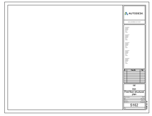
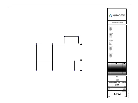
Step 19: Click on place a view from view tab.
Step 20: Place the view in the sheet and adjust the scale if needed , here 1:50 scale is used.
f. S103- Roof Framing Plan
Step 21: Create sheet from the view tab.
Step 22: Rename the sheet number and name to Roof Framing Plan.
Step 23: Click on place view and place the roof plan in the sheet
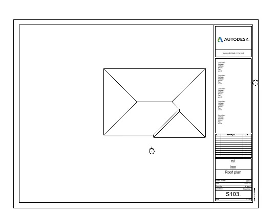
g. A201- North-South elevations
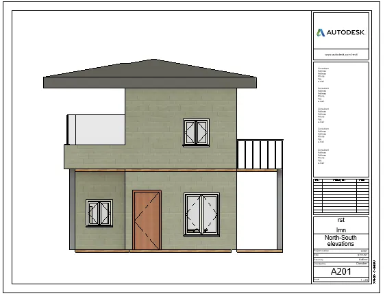
Step 24: To create elevations, in view tab click on elevations and place the elevation in between North and South and rename the created elevation as North- South.
Step 25 : Click on sheets from the view tab.
Step 26: Rename the number and sheet name to A201- North- South elevations.
Step 27 : Click on place view and place elevation North -South.
Step 28: Click on the viewport window and level (in elevation view only) and right click and hide element to hide the window and level in sheet.
Step 29 : To unhide click on reveal hidden elements in the bottom tab, then click on the hided element displayed , then right click and there will be an option to unhide elements, click on reveal again to exit from it.
Step 30: Place the image in the centre.
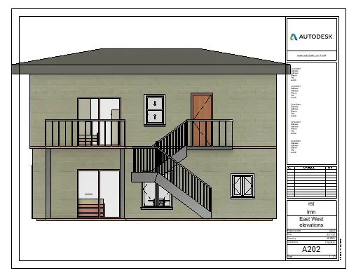
h. A202- East -West elevations
Step 31: Create elevation from the view tab - elevation and place the elevation between East and West.
Step 32: Expand the elevation tab and rename the name to East -West elevation.
Step 33: Create sheet from the view tab - sheet and renameit toA202- East West elevation.
Step 34 : Click on place view and seelct the east- west elevation created.
Step 35 : Adjust the view and scale it accordingly.
i. Sections:
Step 36: Create section by clicking section tab for each rooms.
Step 37: As the sections are already created , craete sheets and place them in each sheet.
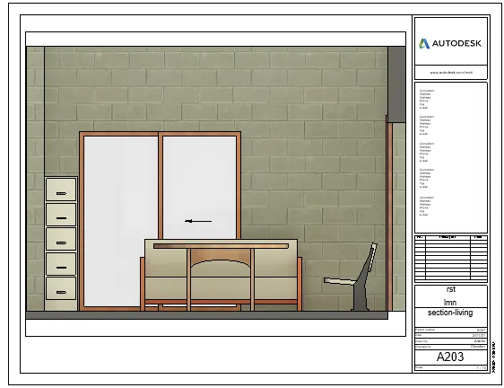
Step 38 : Click on sheet from the view tab, and rename it as A 203- Section -living.
Step 39: Click on place view and place the section view created.
Step 40: Create sheet for dinning section from view tab A204- dinning section.
Step 41: Place the section view- dinning.
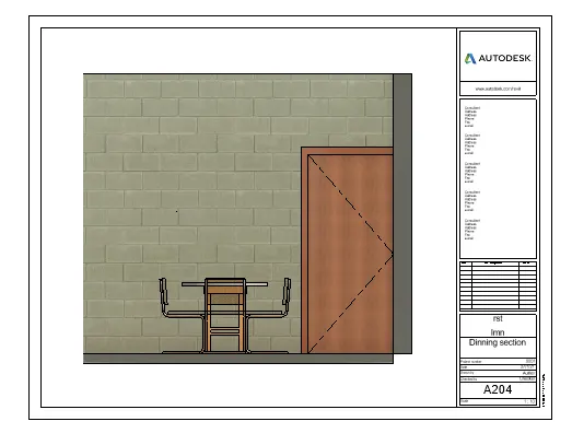
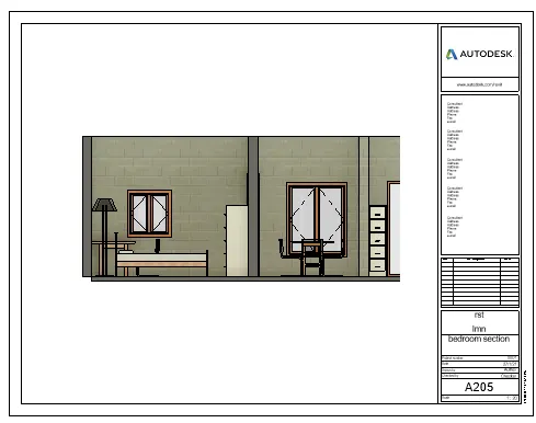
Step 42: Create sheet from view tab and rename it to A205- Section bedroom
Step 43 : Click on place view and place the section of bedroom and adjust the scale.
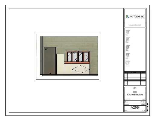
Step 44: Similarly create sheet for kitchen A206- Kitchen -section
Step 45: Click on place a view and place the section view of kitchen.
Result:
Respective sheets are created using sheet template
a. A101- Ground Floor Architectural Plan
b. A102 - First Floor Architectural Plan
c. A103- Roof Plan
d. S101- Ground Floor Structural Plan
e. S102- First Fllor Structural plan
f. S103- Roofframing Plan
g. A201- North -South elevations
h. A202- East West elevations
i. A203-A206 Sections
10. Creating camera views for each room and creating sheets for the views.
Aim : Creating camera views for each rooms and creating sheets for each of the 3d view.
Procedure:
Creating views :
Step 1: Go to floor plan , from the view option-3d view- click on camera , and place the camera in which room we need the view.
Step 2: Created views will be seen under 3d in property browser.
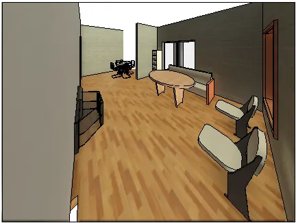
Living:
Step 3: Place the camera in the living room, in the floor plan.
Step 4: Click on the 3d view created from the property browser and rename it to living
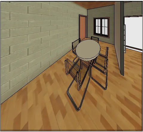
Dinning :
Step 5 : Click on camera from view tab under 3d view.
Step 6 : Place the camera such that the dinning view is visible.
Step 7 : Expand the 3d view from the property browser and rename it to dinning.
Step 8 : Click on the dinning view.
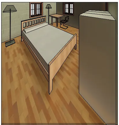
Bedroom:
Step 9: Click on camera from view tab under 3d view.
Step 10 : Place the camera such that the bedroom view is visible.
Step 11 : Expand the 3d view from the property browser and rename it to bedroom.
Step 12 : Click on the bedroom view.
Kitchen :
Step 13: Click on camera from view tab under 3d view.
Step 14 : Place the camera such that the kitchen view is visible.
Step 15 : Expand the 3d view from the property browser and rename it to kitchen.
Step 16 : Click on the kitchen view.
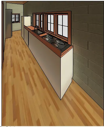
Restroom:
Step 17: Click on camera from view tab under 3d view.
Step 18 : Place the camera such that the restroom view is visible.
Step 19 : Expand the 3d view from the property browser and rename it to restroom.
Step 20 : Click on the restroom view.
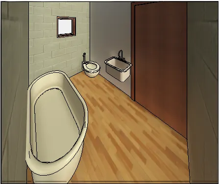
Store:
Step 21: Click on camera from view tab under 3d view.
Step 22 : Place the camera such that the store view is visible.
Step 23 : Expand the 3d view from the property browser and rename it to store.
Step 24 : Click on the store view.
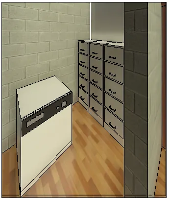
Creating sheets:
Step 25 : To create sheet , go to view tab click on sheet , seelct the sheet we need or load more and seelct the required.
Step 26 : Rename the sheet name as A501 - Living room
Step 27 : Click on place view and click on the living from the dialogue box.
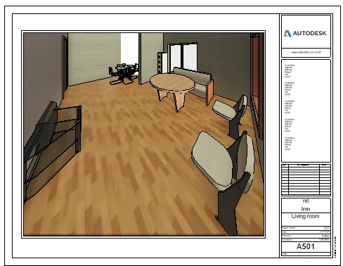
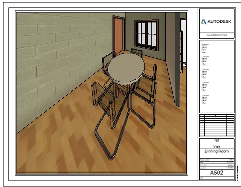
Step 28: Create another sheet from the view tab, rename it to A502 - Dinning room.
Step 29: Click on place a view , and select the dinning room.
Step 30: Create another sheet from view tab, and rename it to A503- Bedroom.
Step 31: Click on place a view and place the bedroom view.
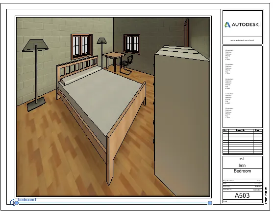
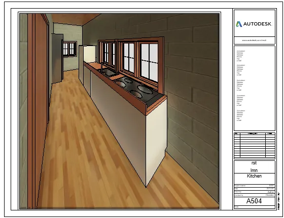
Step 32: Create new sheet from view tab, and rename it as A504- Kitchen.
Step 33: Click on place view and place the kitchen view.
Step 34: Create another sheet and rename it to A505- Restroom
Step 35: Place the view of restroom in the sheet.
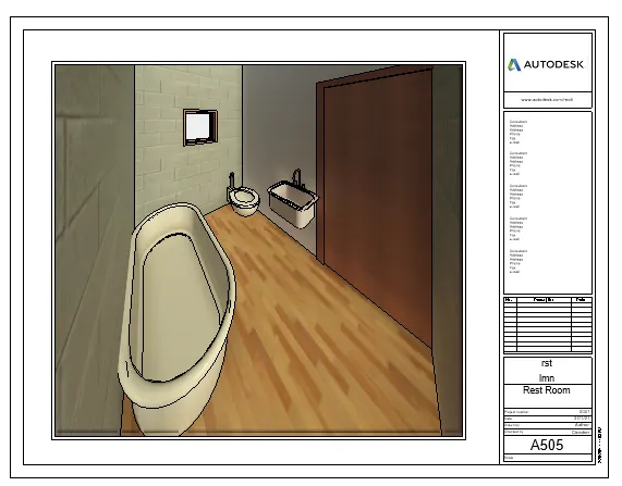
Step 36 : Create a new sheet and rename it to A506- store room
Step 37: Click on place a view and place the store room.
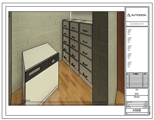
Result:
Camera views of all rooms are created and sheets are created accordngly.
Views:
Living
Dinning
Bedroom
Rest room
Kitchen
Store
Sheets:
A501- Living room
A502- Dinning Room
A503- Bedroom
A504- Kitchen
A505- Restroom
A506- Store