3D Creation of Celing, Roof, Architectural plan, Structural plan, Sectional view, Elevation view and Camera specific view for a house plan using REVIT
1) Based on the project saved from Week 3, proceed from the First Floor Level. Model a Ceiling from the architecture tab above the walls at the first-floor level
AIM : To create ceiling at the first floor level
INTRODUCTION : Ceilings are resided above the walls. It is created using ceiling tool at a specified distance from the level. To place ceiling, walls are selected or sketched the boundaries. There are two types of ceiling : Basic ceiling and Compund ceiling. Basic ceiling has no thickness and compund ceiling has many layers with thickness. Structure and thickness of ceiling can be modified in revit software.
PROCEDURE :
- Open week 3 project
- Go to level 1
- Select ceiling (600x600mm_grid) from architectural tab and then select automatic ceiling
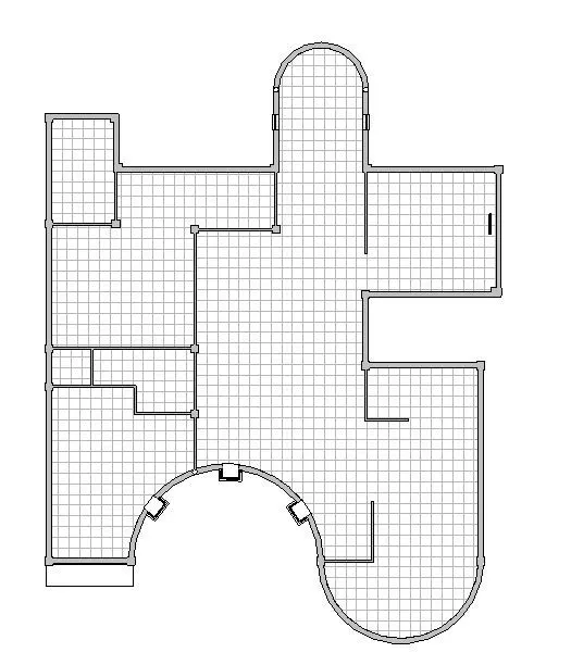
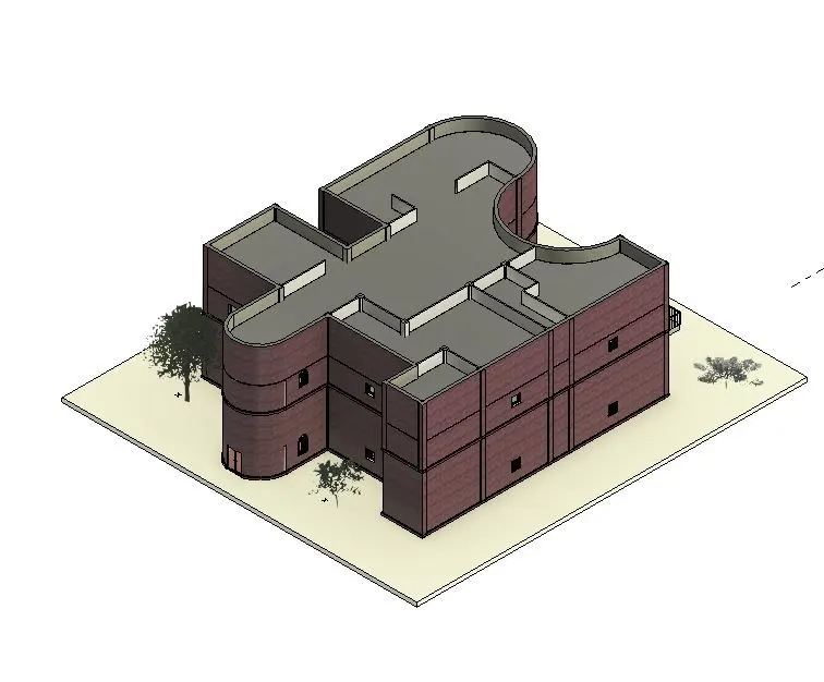
- Select the rooms and ceiling is created at 16' height
RESULT :
2) Model a roof above the ceiling by selecting the footprints of the ceiling. Using the adjustment toolbars appearing on-screen adjust the roof slope to 10 degrees
AIM : To create roof with 10 degree slope above ceiling
INTRODUCTION : Roof is a top covering of a building. In revit software, roof can be modified like change its shape, creating openings, defining slope, adding overhang value for eaves, adding soffits, fascia, gutters etc. Revit offers several methods to create roof such as
- Roof by footprint
- Roof by extrusion
- Roof by face
PROCEDURE :
- Go to level 2 in floor plan
- Click on roof by foot print in architectural tab
- Select boundary line and pick the lines
- Press ok
- Select the roof and "add points" at some points for creating sloped roof
- Click on modify sub elements and click on the points added
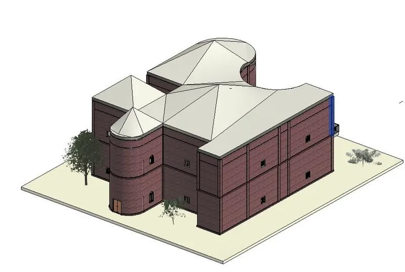
- Edit it by adding slope of 10 degree
- Press okay
RESULT :
3) Using the file saved from weeks 2 to 4, create plan views for ground floor level and first-floor level including all the walls, floors, and components. Separate them to architecture and structural plans
a. Architecture plan must have walls, floors, and all the components placed within the building
b. Structure plan must have details of only walls, floors, and columns
AIM : i) To create plan views for ground floor and first floor level
ii) To separate components to architectural and structural plan
INTRODUCTION : In revit software, plan view in view tab is used to create various views which include floor plan, reflected ceiling plan, structural plan, plan region and area plan. Floor plan views are the default views which are created automatically when levels are added and structural plan views are the default views which are created automatically when levels are added using structural template
PROCEDURE :
- Click on view tab
- Select floor plan under plan views
- Untick Dont duplicate existing views
- Now select ground floor ie level 0 in the model
- Ground floor view is created
- Copy and paste the whole beside original
- Remove all components except walls, floor for structural plan
- Create grid lines and columns accordingly
- Ground floor structural view is created
- Similarly create for first floor also
RESULTS :
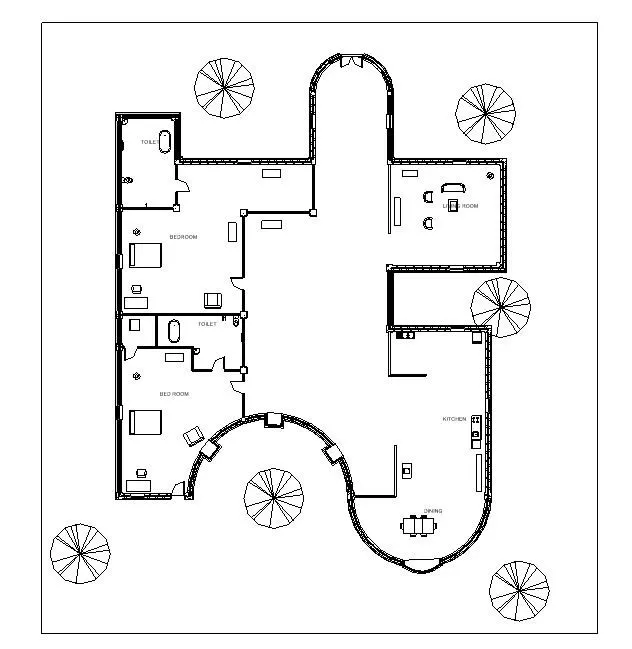
GROUND FLOOR ARCHITECTURAL VIEW
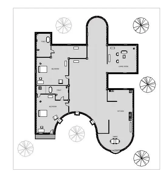
FIRST FLOOR ARCHITECTURAL VIEW
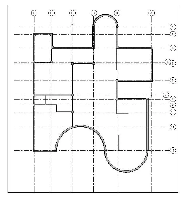
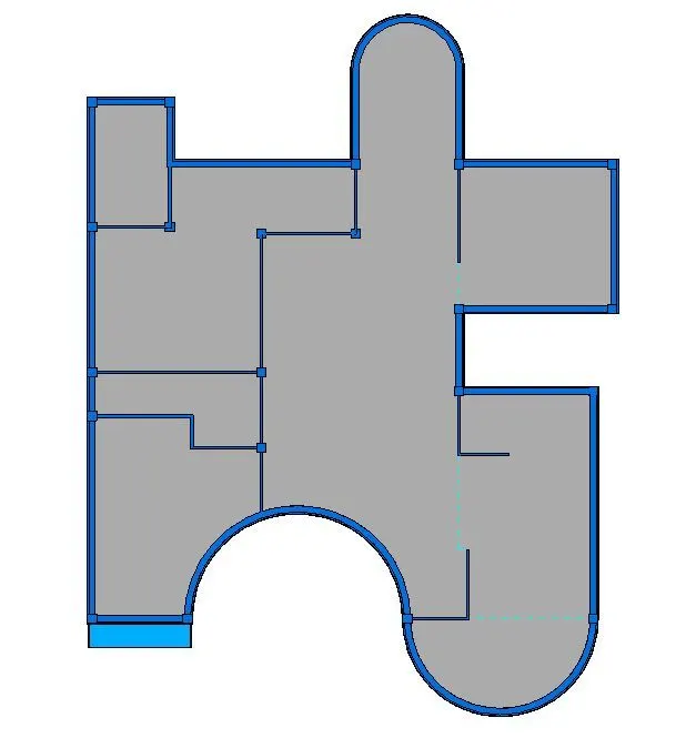
GROUND FLOOR AND FIRST FLOOR STRUCTURAL VIEW (PROJECT BROWSER-STRUCTURAL PLANS)
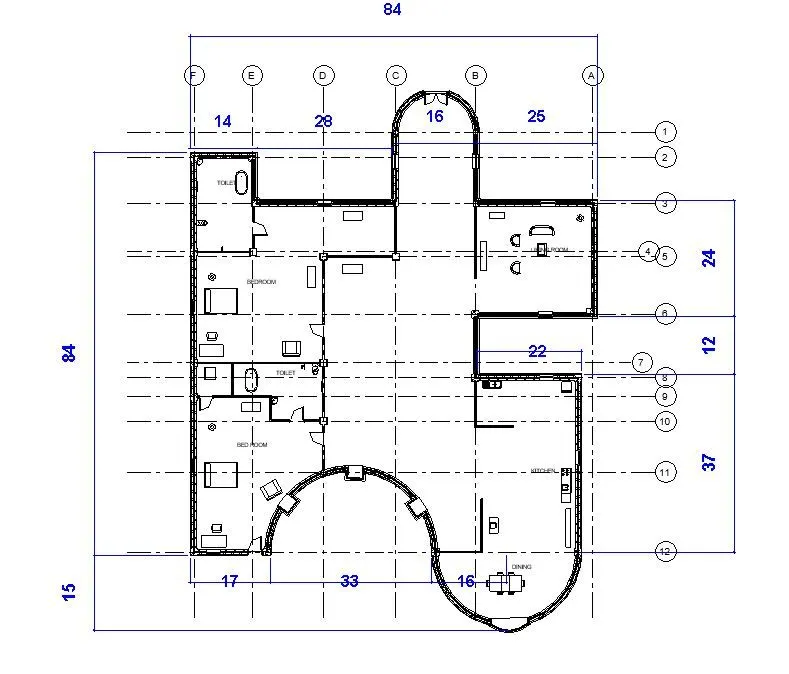
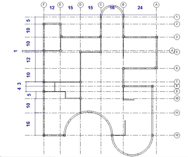
4) Using annotate toolbar add dimensions to all the walls and floors with reference to the longitudinal and transverse grids created in the project file
a. The architecture plan dimensions include details on where the components are placed within the buildings with relation to grids. Overall dimensions are sufficient for architecture plans
b. The Structure plan dimensions must include details on the position of all the walls and interior walls with reference to grids. Locate all the framing components of the building with reference to a fixed point using Structural plans
AIM : To add dimensions to walls and floors with reference to longitudinal and transverse grids
INTRODUCTION : Dimensions show measurements in a project. In revit software, annotate toolbar consists different tools for measuring a structure such as linear, aligned, angular, radial and arclength. Properties of dimensions is also adjusted accordingly. Grid lines are used to place columns in building design. Revit automatically numbers longitudinal and transverse grid lines which can be edited and lines can be aligned in same level.
PROCEDURE :
- Select linear tool in annotate tab
- Mark the dimensions in architectural plan
- Similarly select linear tool and mark the dimensions for structural plan
- Select linear dimensions type tool and create a duplicate
- Edit the colour, line weight of the dimensions
RESULTS :
Dimensions of architectural plan for ground floor and first floor
Dimensions of structural plan for both groundfloor and first floor
5) Create a sheet template from the view tab and adjust the parameters on the sheet to add appropriate views
AIM : To create template sheet and add ground floor and first floor views
INTRODUCTION : Revit software provides project templates in which different views of building model is created for the documentation process. These list of templates are available in "Load autodesk family".
PROCEDURE :
- Click on insert and select load autodesk family
- Select title blocks and select A0 sheet
- From sheets in the project browser insert it
- Edit the title block according to the project
- Views are created for ground floor and first floor
- Click on add view in the view tab and add views of ground floor and first floor in two sheets
RESULTS :
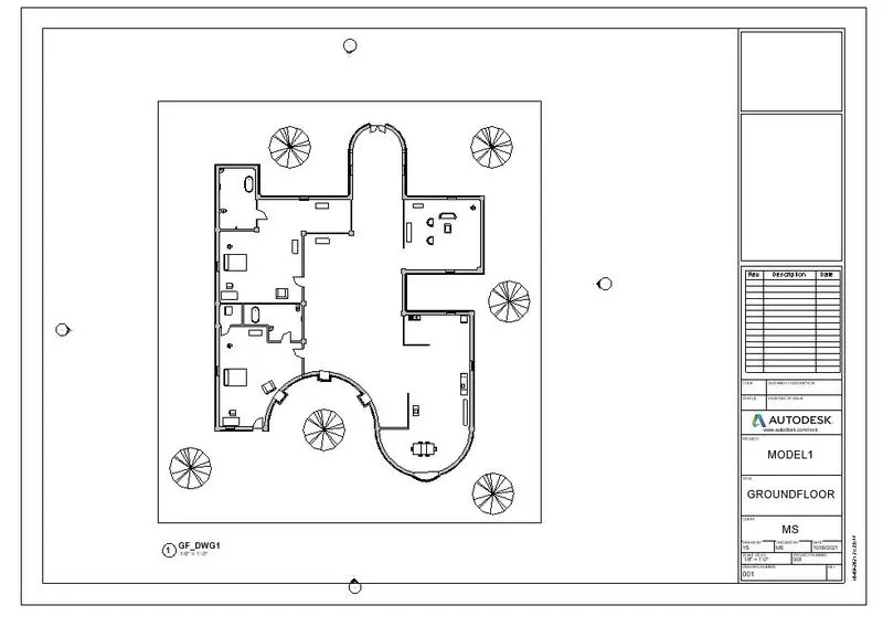
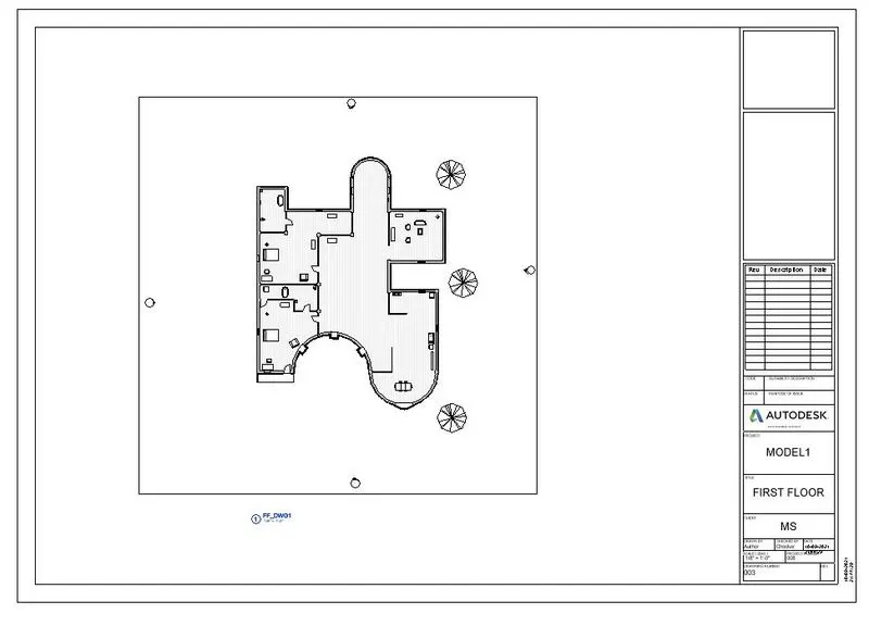
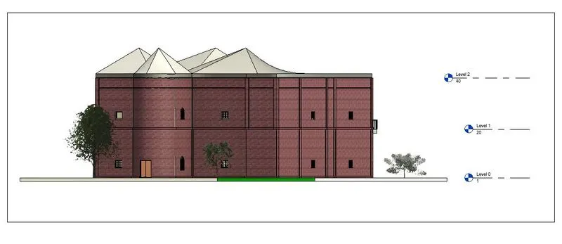
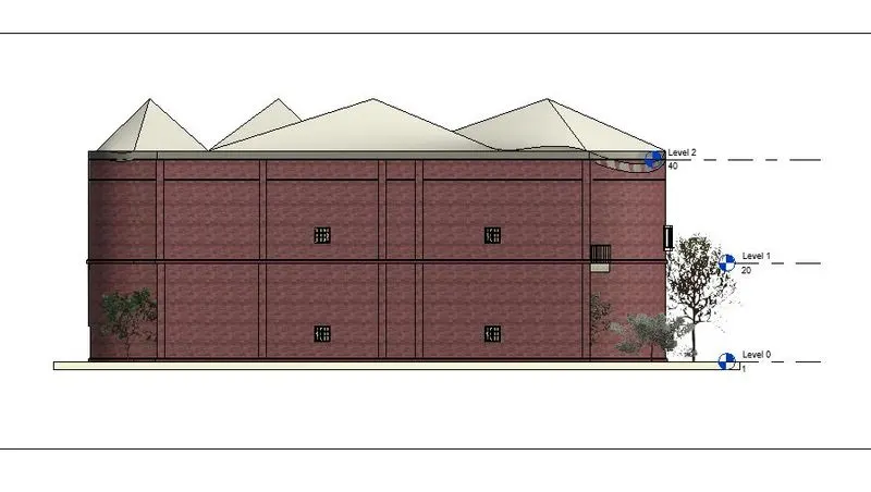
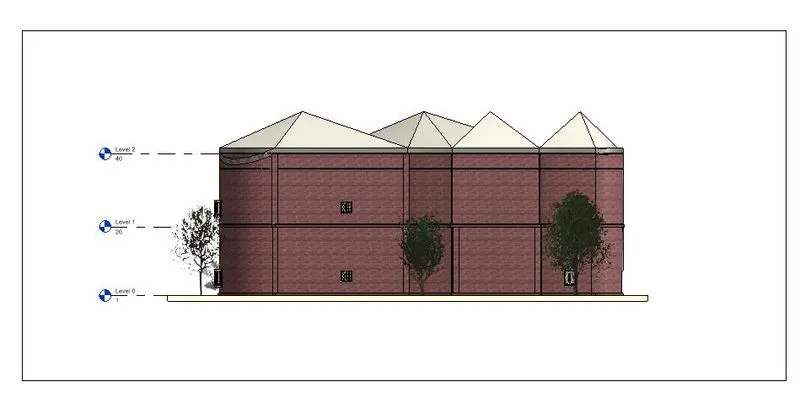
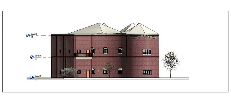
6) Using the elevation tab create the elevation views, looking at your building from East, North, South, and West
AIM : To create elevation views of buildings from directions east, west, north and south
INTRODUCTION : To see interior and exterior perspectives in the revit, elevations are created.
PROCEDURE :
- Select elevation in view tab
- Place north, west, south and east elevation
- Select elevations in project browser and view the different elevations
RESULT :
NORTH
WEST
EAST
SOUTH
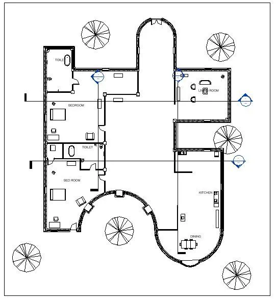
7) Produce section cut through each room either cutting across longitudinally or in a transverse direction
AIM : To view rooms through section cut Longitudinally and transverse directions
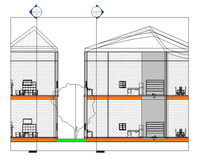
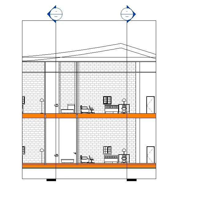
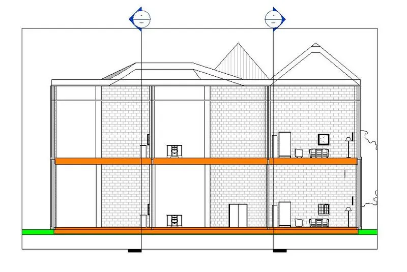
INTRODUCTION : Sectional views are used to see interior views of the building by cutting through model in longitudinal or transverse direction. Cutting plane passing through model is an imaginary plane which is indicated by section line.
PROCEDURE :
- In view tool bar click on sections
- Create longitudinal and transverse sections across the layout
- Double click on sections to various sections created
RESULTS : SECTIONS ARE CREATED
SECTION 1
SECTION 2
SECTION 3
SECTION 4
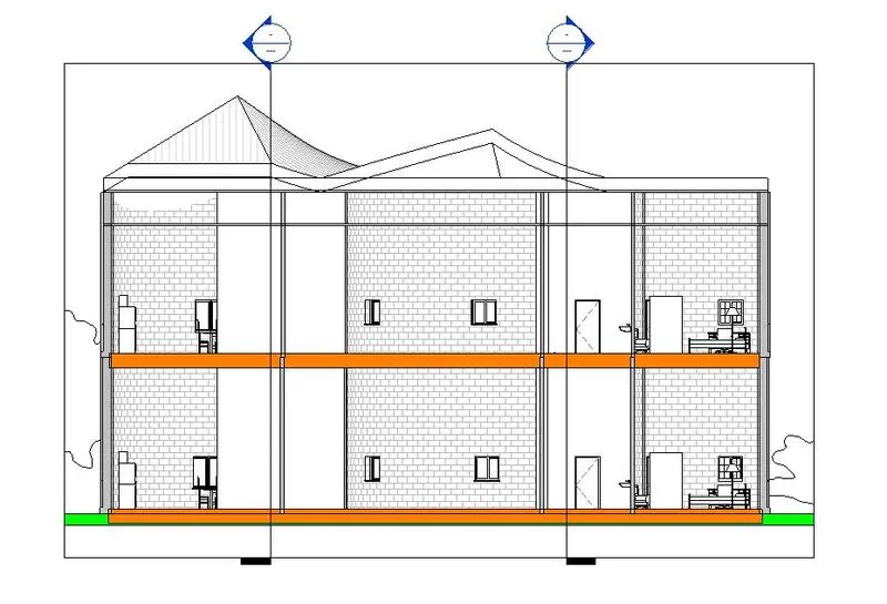
8) Classify the views, Plan Views, Section Views, and Elevation views to either Design or Documentation category using Properties browser
AIM : To classify views for design or documentation using project browser
INTRODUCTION : Revit software provides browser organisation in project browser which organises and classifies views, sheets and schedule that is based on type and discipline. Within groups, items are sorted in ascending or descending order.
PROCEDURE :
- Right click on views and select browser organisation
- Then select type/discipline in views and click on apply to the project
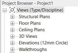
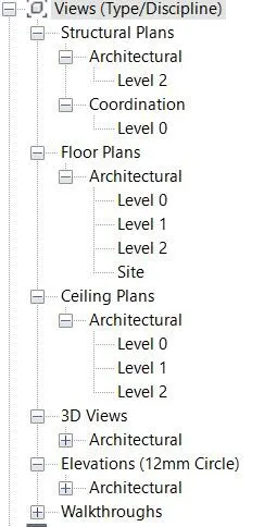
- Now views are arranged according to type/discipline i.e :
- Structural plans
- Floor plans
- Ceiling plans
- 3D views
- Elevation
- Walk through
RESULTS :
Organised project browser
9) Using the sheet template produced create multiple sheets as follows
a. A 101- Ground Floor Architecture Plan
b. A 102- First Floor Architecture Plan
c. A 103- Roof Plan
d. S 101- Ground Floor Structural Plan
e. S 102- First Floor Structural Plan
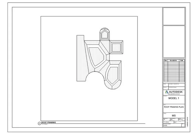
f. S 103- Roof Framing Plan
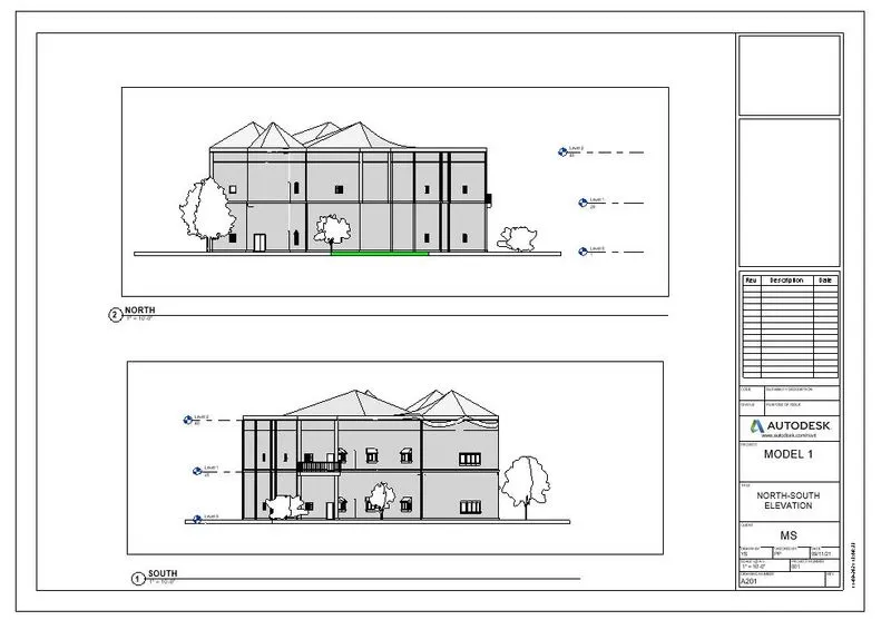
g. A-201- North-South Elevations
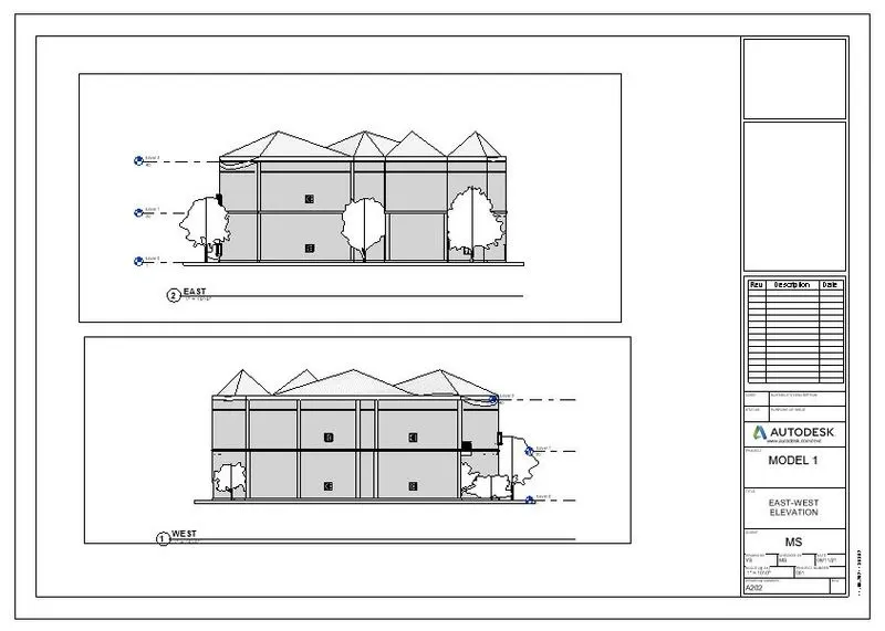
h. A-202- East-West Elevations
Add additional sheets based on the sections created in your Revit file
AIM : To create multiple sheets for architectural plans, structural plans, roof plans and elevation plans
INTRODUCTION : Revit software provides various templates which can be edited and saved. In these templates, specification of the drawing is edited and saved such as project name, sheet name, date, scale, author, owner etc which is useful for the project documentation.
Various views are added and sheets are named accordingly.
PROCEDURE :
- Select "Load autodesk family" in insert tab
- Insert A1 sheet from title blocks
- Select sheet in view tab
- Create 9 number of sheets
- Insert views in the sheet
- In all sheets parameters are edited as
- Project name : MODEL 1
- Sheet name edited according to various views
- Client : MS
- Author : YS
- Checked by PP
- Date : 09/11/21
- Project number : 001
- Drawing number edited according to type of drawing
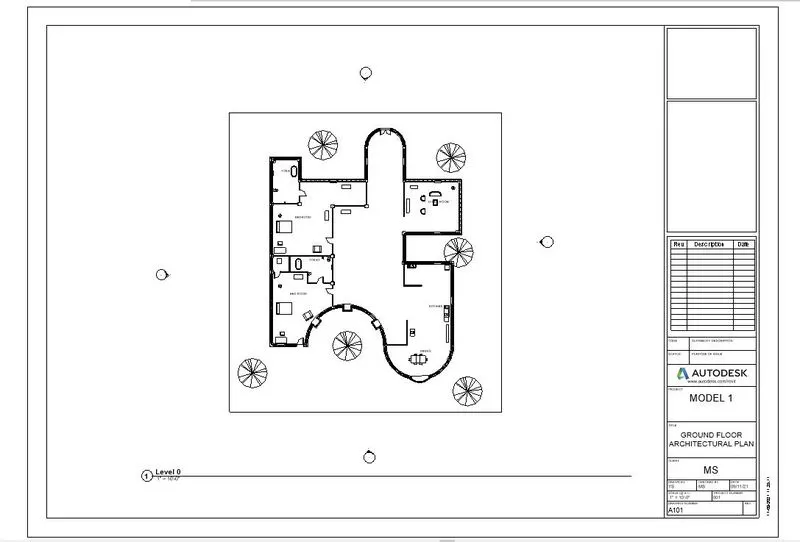
- In the 1st sheet add ground floor architecture plan and name the sheet as ground floor architecture plan, drawing number as A101
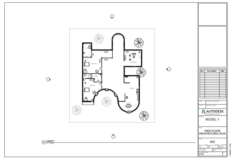
- In the 2nd sheet add first floor architecture plan and name the sheet as first floor architecture plan, drawing number as A102
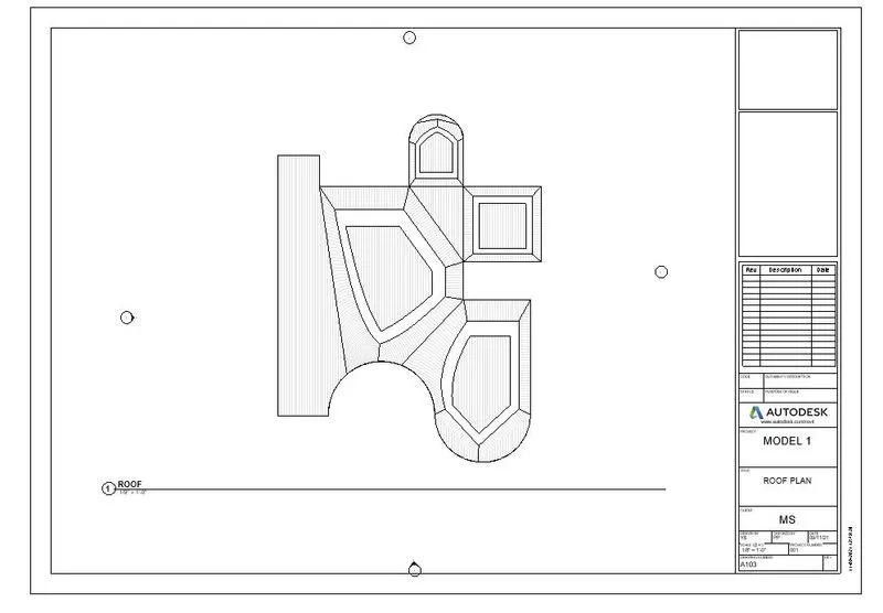
- In the 3rd sheet add roof plan and name the sheet as roof plan, drawing number as A103
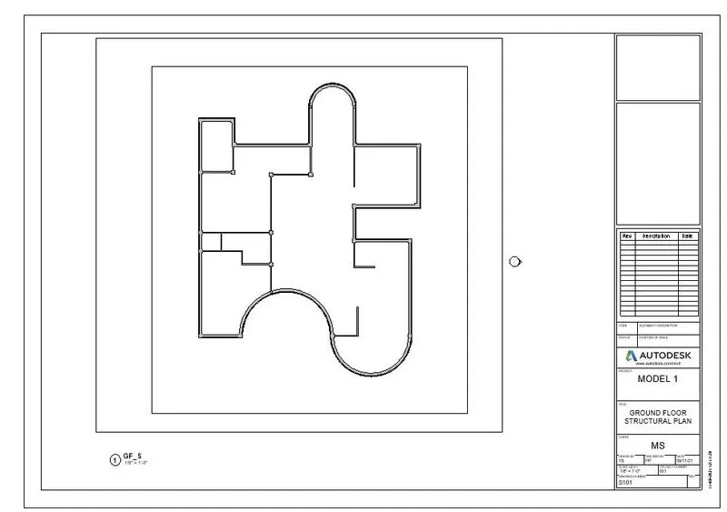
- In the 4th sheet add ground floor structural plan and name the sheet as ground floor structural plan, drawing number as S101
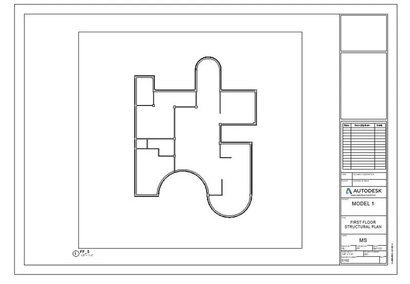
- In the 5th sheet add first floor structural plan and name the sheet as first floor structural plan, drawing number as S102
- In the 6th sheet add roof framing plan and name the sheet as roof framing plan, drawing number as S103
- In the 7th sheet add north- south elevations and name the sheet as north-south elevation, drawing number as A-201
- In the 8th sheet add east west elevation and name the sheet as north-south elevation, drawing number as A-202
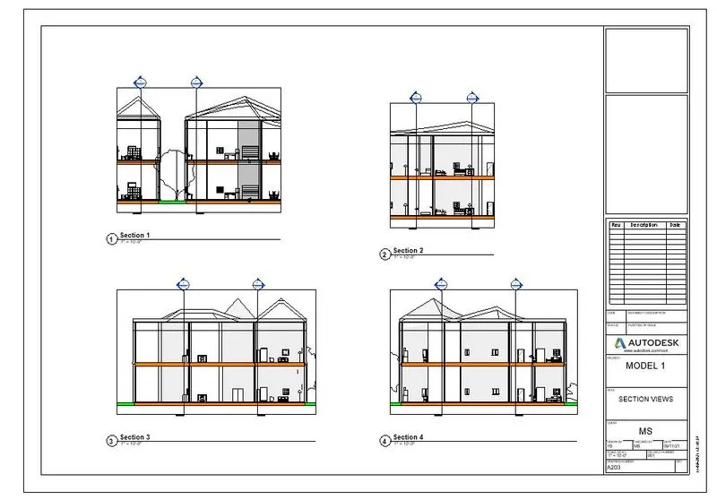
- In the 9th sheet add section views and name the sheet as sections, drawing number as A-203
RESULTS :
Various drawing sheets are created
Ground Floor Architecture Plan
First Floor Architecture Plan
Roof Plan
Ground Floor Structural Plan
First Floor Structural Plan
Roof Framing Plan
North-South Elevations
East-West Elevations
SECTION VIEW
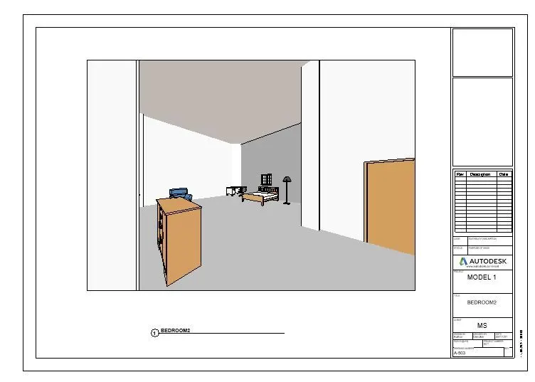
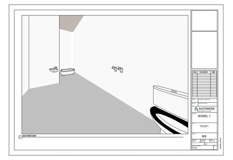
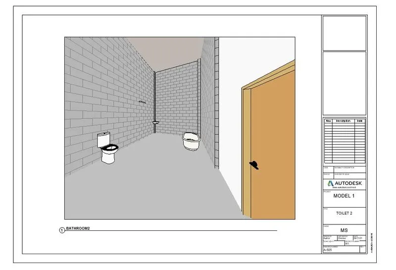
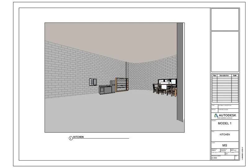
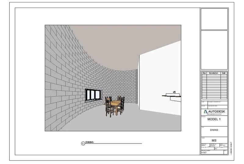
10) Create a camera-specific view or a 3D view in each room ( living, dining, bedroom). Based on the views create a new set of sheets starting A-501 (you can add as many sheets after, 502, 503.. n)to place the 3D view images. Produce the sheets as a part of project drafting.
AIM : To create 3D view in each room and adding 3D views to sheets
INTRODUCTION : Revit software provides various templates which can be edited and saved. In these templates, specification of the drawing is edited and saved such as project name, sheet name, date, scale, author, owner etc which is useful for the project documentation. Various views are added and sheets are named accordingly.
PROCEDURE :
- Select camera in 3D view
- Place camera at all rooms and save it
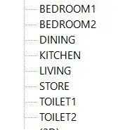
- Create drawing sheets at series A-501 for all the rooms and rename as shown below
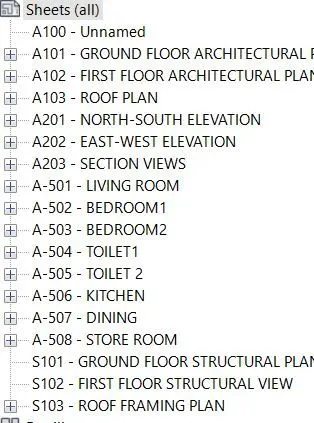
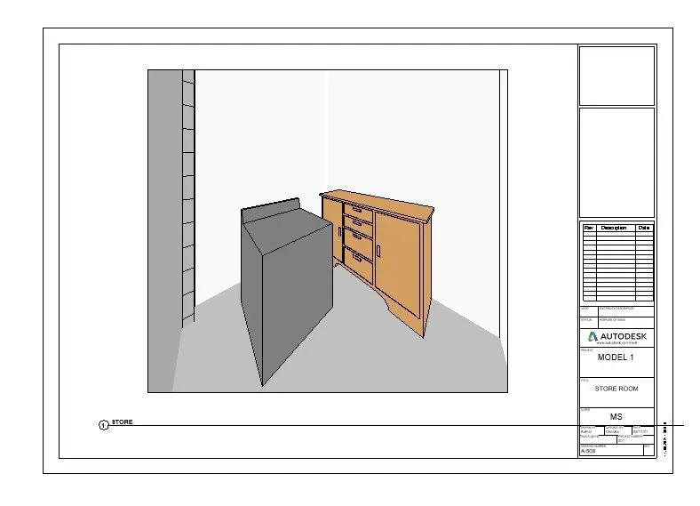
RESULTS :
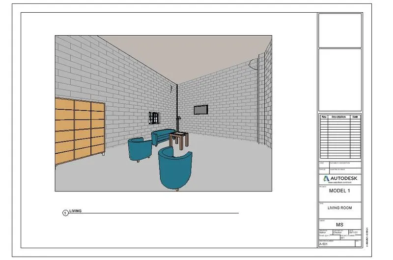
LIVING ROOM
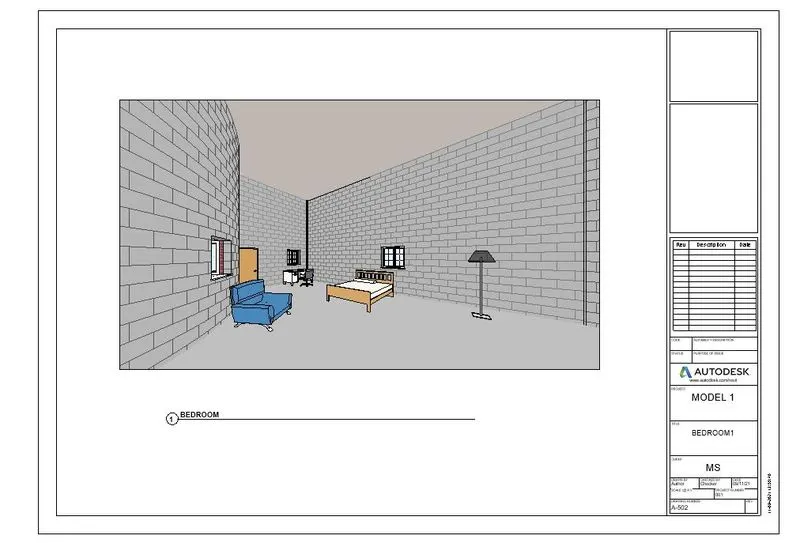
BEDROOM1
BEDROOM2
TOILET1
TOILET2
KITCHEN
DINING
STOREROOM