3D Creation of Celing, Roof, Architectural plan, Structural plan, Sectional view, Elevation view and Camera specific view for a house plan using REVIT
- Based on the project saved from Week 3, proceed from the First Floor Level. Model a Ceiling from the architecture tab above the walls at the first-floor level
AIM :
To create celling from the Architecture tap
PROCEDURE :
STEP 1:
- Open the window
- Go to the “REVIT SOFTWARE 2023”
- Click “OPEN”
- Go to the “FILE TAP”
- Go to the “Open” tap
- Select the “RESIDENTIAL UNIT FEET AND INCHES “ as a previse drawing
- Click “OPEN”
STEP 2:
- Go to the “PROJECT BROWSER “
- Go to the “FLOOR PLAN”
- Select the “FIRST FLOOR “ Plan
- Go to the “ARCHITECTURE” TAP
- Click the “celling” tap
- U will get another tap called “MODFIY / PLACE CELLING”
- Select the “SKETCH CELLING “
- Once you click the “SKECTH CELLING “
- U will get another tap called “MODIFY /CREATING BOUNDRY”
- Select the “PICKLINE” option
- Select the outer wall line and
- Select “tick” mark
- Go to the “3d default view “
- See in the “3dview “ and show the result
RESULT :
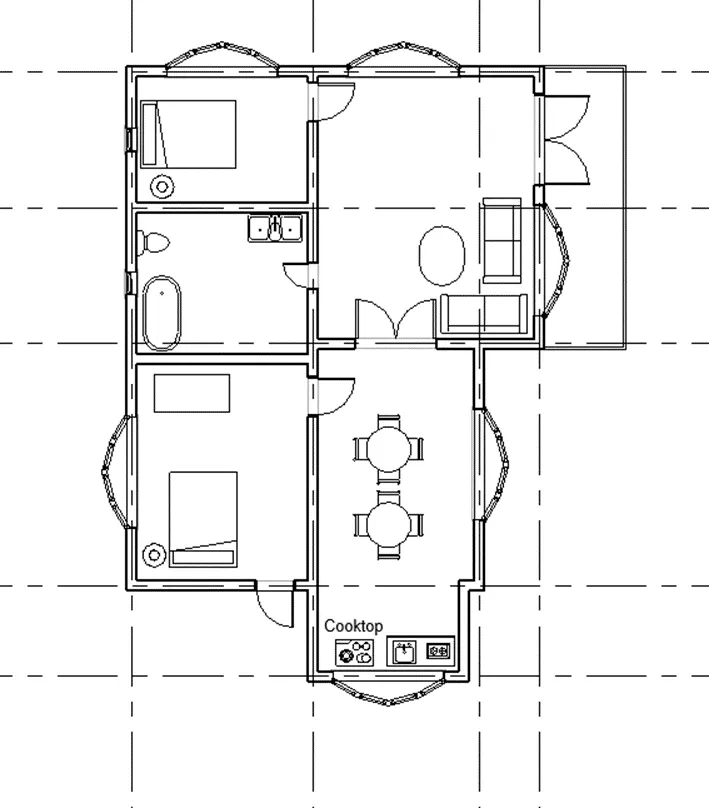
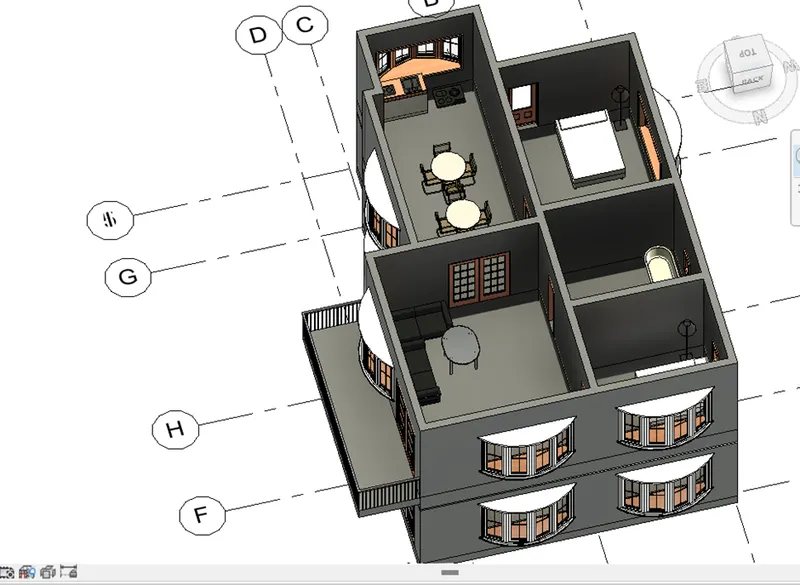
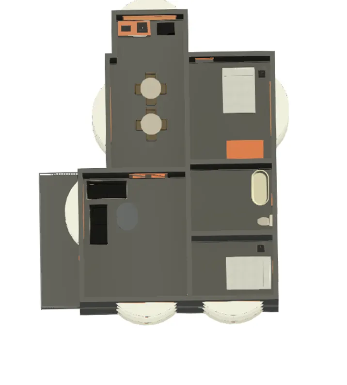
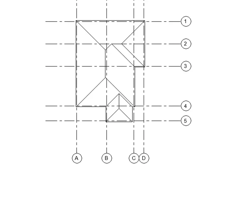
2. Model a roof above the ceiling by selecting the footprints of the ceiling. Using the adjustment toolbars appearing on-screen adjust the roof slope to 10 degrees
AIM:
To create a model a roof above the celling by selecting foot prints of celling .
PROCEDURE :
STEP 1:
- Go to the “project browser “
- Click the “FIRST FLOOR “
- Go to “ARCHITECTURE” TAP
- Go to “ROOF “ Tap
- Select the “ROOF BY FOOTPRINT”
- Select the “PICKLINE “ option
- Select the “EDGE OF THE WALL”
- Click “TICK” option
STEP 2 :
- Enter “UN” command
- U will get dialog box
- Click the “SLOP” and change the unit as “DEGREES”
- than Click “OK”
- Click “OK”
- Go to the “PROPERTY BROWSER “
- Go to the “SLOP”
- Change the slop as “10”
- And finally show the RESULT
RESULT :
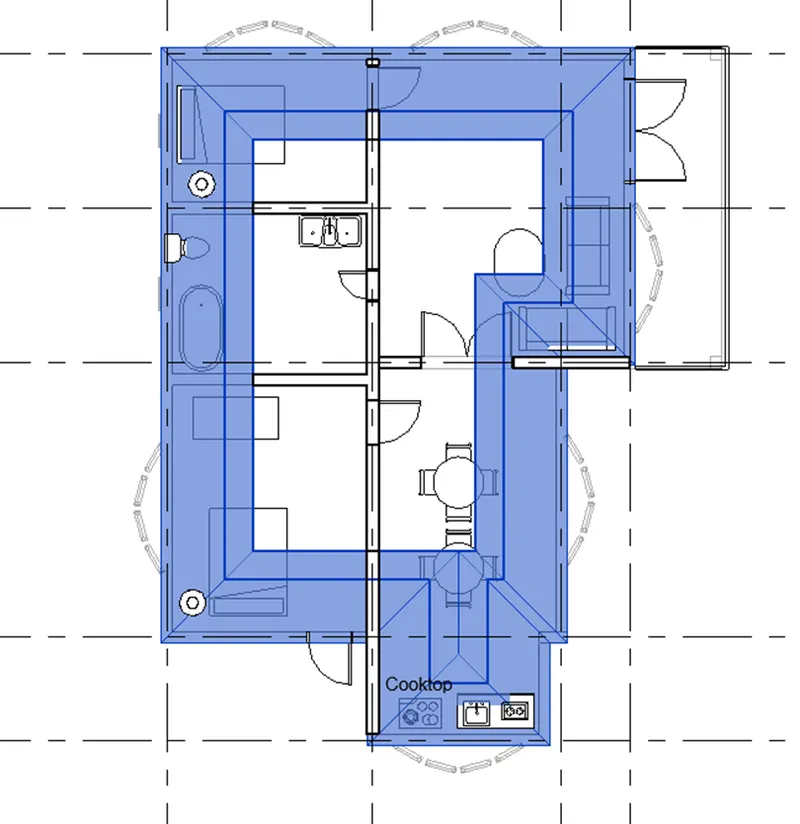
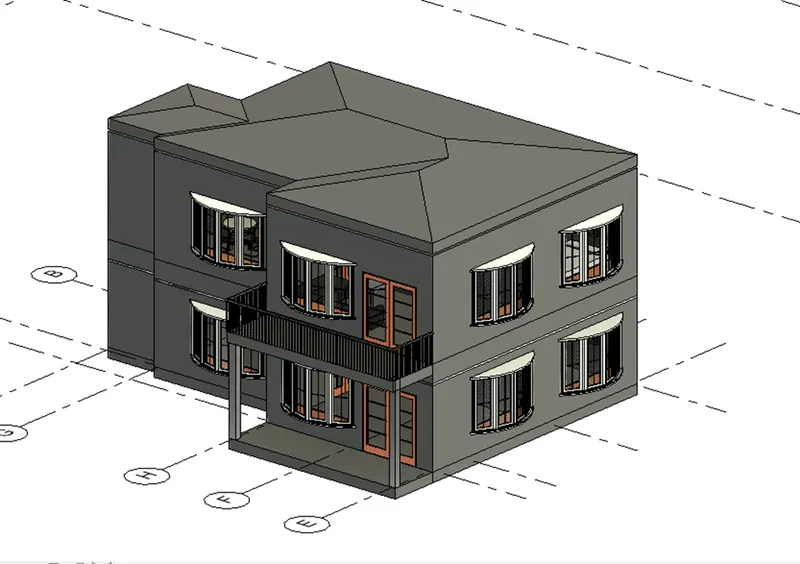
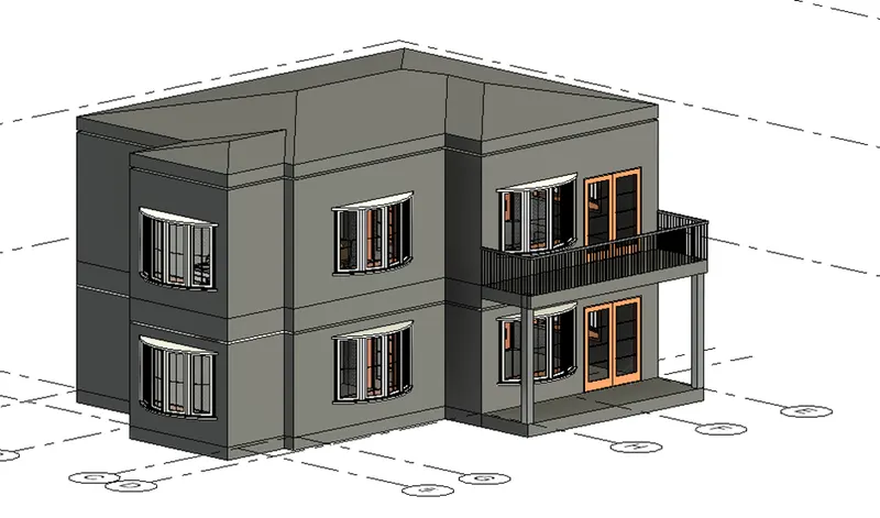
3) Using the file saved from weeks 2 to 4, create plan views for ground floor level and first-floor level including all the walls, floors, and components. Separate them to
architecture and structural plans
- Architecture plan must have walls, floors, and all the components placed within the building
b. Structure plan must have details of only walls, floors, and columns
AIM:
To create the Architecture and Structure plan using Revit software
PROCEDURE
- We already created the layout
- Go to the view “ tap
- Click “PLAN VIEW “
- Click “FLOOR PLAN”
- U will get dialog box
- Go to the “EDIT TYPE”
- Click “OK”
- Than click “OK”
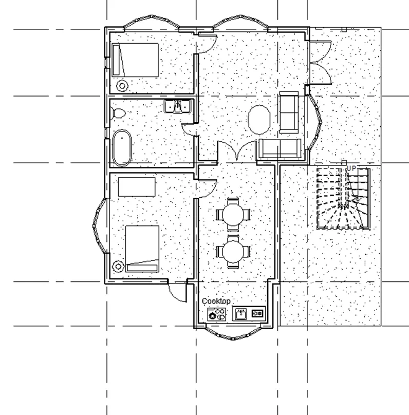
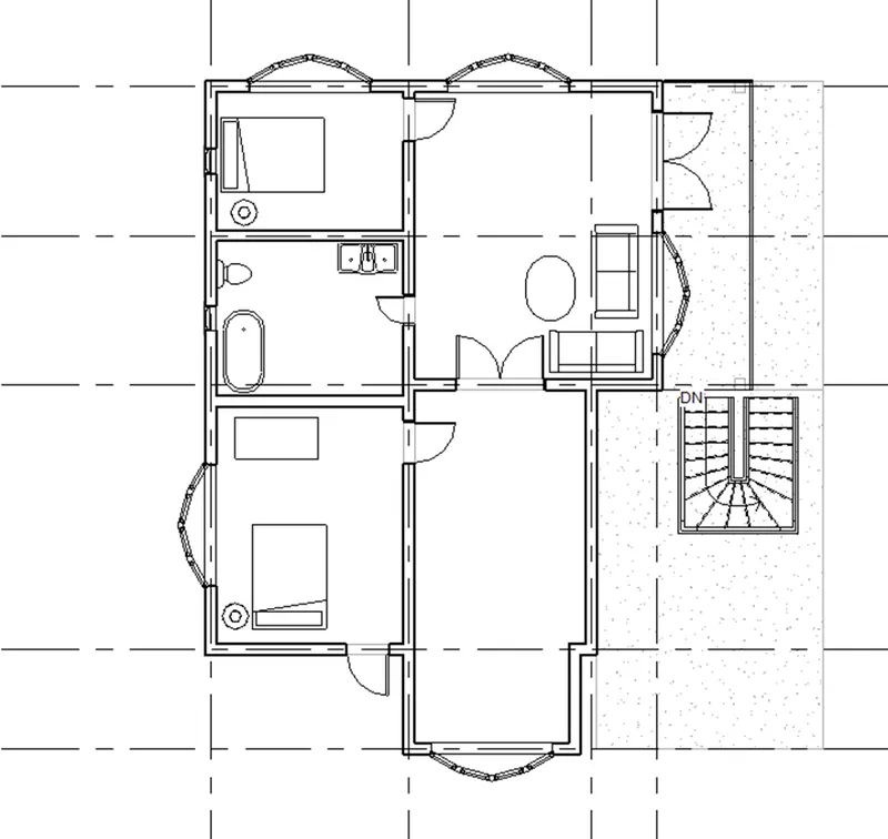
- Architecture floor plan as shown in below for “GROUND AND FIRST” floor
Ground Floor
First Floor :
STRUCTURAL PLAN :
- Go to the “VIEW” tap
- Go to the “PLAN VIEWS”
- Go to “STRUCTURAL PLAN”
- U will get dialog box called “NEW STRUCTRAL PLAN”
- Select the floor which is you like “GROUND & FIRST FLOOR “
- Click “OK”
- Structural floor plan as shown in below for “GROUND AND FIRST” floor
- Finally show the structural and Architecture plan in result
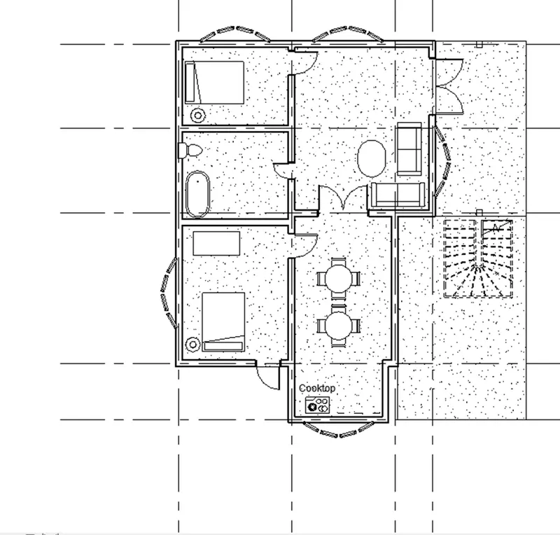
GROUND FLOOR :
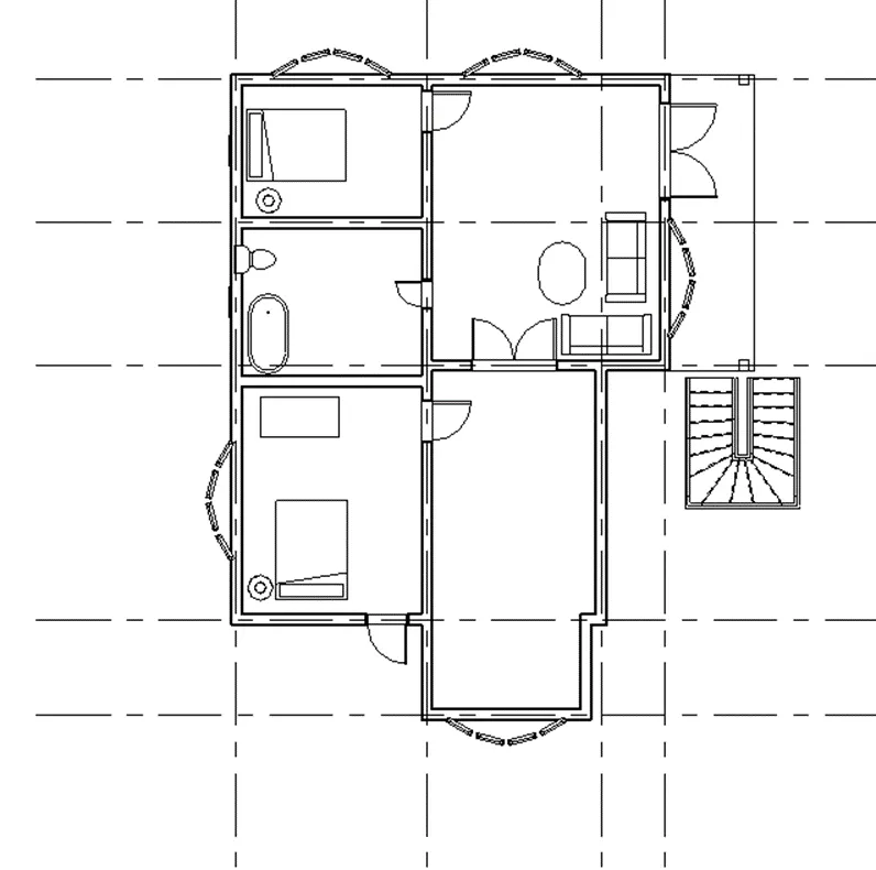
FIRST FLOOR :
RESULT :
Architecture plan result :
GROUND FLOOR :
FIRST FLOOR :
STRCTURAL PLAN :
GROUND FLOOR :
FIRST FLOOR :
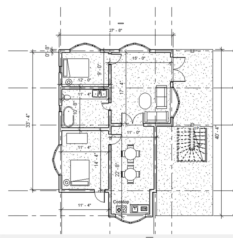
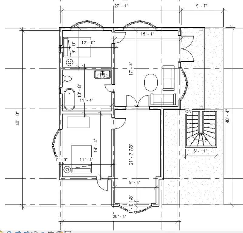
4) Using annotate toolbar add dimensions to all the walls and floors with reference to the longitudinal and transverse grids created in the project file
- The architecture plan dimensions include details on where the components are placed within the buildings with relation to grids. Overall dimensions are sufficient for architecture plans
- The Structure plan dimensions must include details on the position of all the walls and interior walls with reference to grids. Locate all the framing components of the building with reference to a fixed point using Structural plans
Aim :
To create a Annotation for architecture and Structural plan
Procedure :
STEP 1:
- Go to the “ARCHITECTURE PLAN “
- Go to the “ANNOTATION” tap
- Then choose “LINEAR” or “ALIGNED”
- Then carefully click the edge of the wall
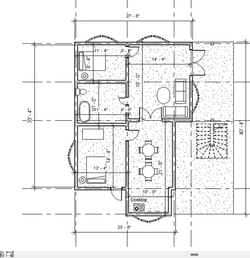
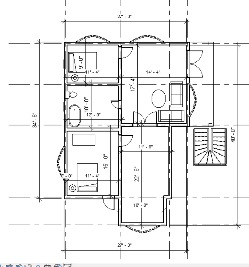
- Show dimension for all the rooms and wall
GROUND FLOOR :
FIRST FLOOR :
STEP 2:
- Go to the “STRUCTURAL PLAN “
- Go to the “ANNOTATION” tap
- Then choose “LINEAR” or “ALIGNED”
- Then carefully click the edge of the wall
- Show dimension for all the rooms and wall
- Finally show the result
GROUND FLOOR :
FIRST FLOOR :
RESULT :
ARCHITECTURE PLAN :
GROUND FLOOR :
FIRST FLOOR :
STRUCTURAL PLAN:
Ground floor :
FIRST FLOOR :
5) Create a sheet template from the view tab and adjust the parameters on the sheet to add appropriate views
AIM :
To create a sheet template from the view tab and adjust the parameter on sheet to add appropriate view
PROCEDURE :
- Go to the Revit software
- Go to the previse drawing
- Open the “Residential drawing feet and inches “
- Go to view the “VIEW” tap
- Click the “sheet” option in the view tap
- U will get a dialog box called “ NEW SHEET “
- Select the “A1 METRIC”
- Click “OK”
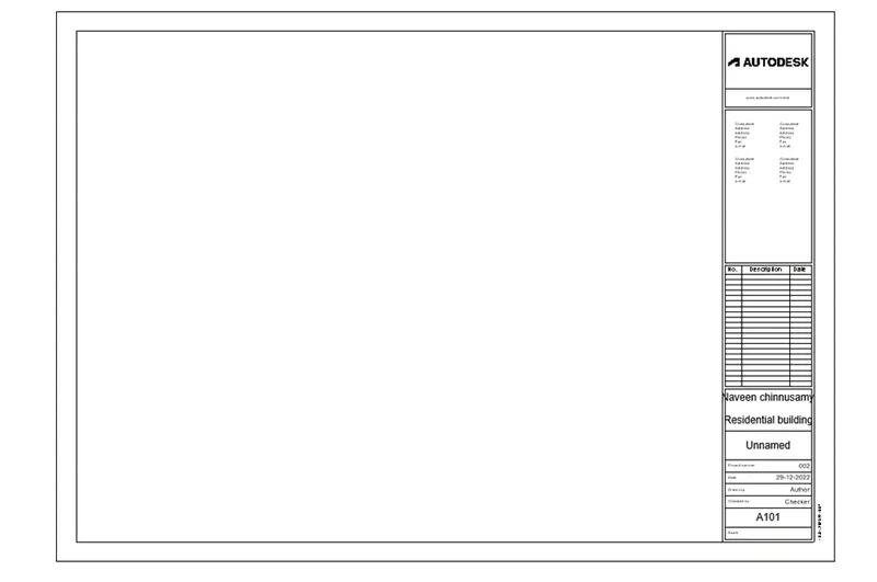
- u will get a sheet as shown in below
- Go to the “MANAGE “tap
- Give change the “PROJECT INFORMATION” as per your requirement
- Once you get the sheet
- Go to the “SHEET”
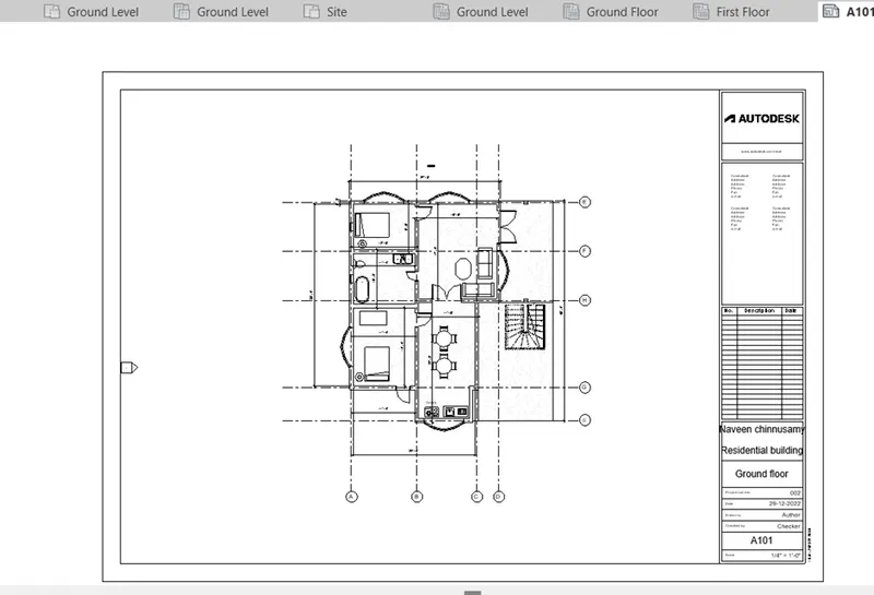
- Set the name as “GROUND FLOOR”
- Select the “GROUND FLOOR “ drawing
- Drag view in to the sheet as shown in below
GROUND FLOOR :
FIRST FLOOR :
- Go to the “SHEET”
- Set the name as “FIRST FLOOR”
- Select the “FIRST FLOOR“ drawing
- Drag view in to the sheet as shown in below
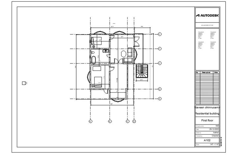
RESULT :
A 101- GROUND FLOOR
A-102 -FRIST FLOOR :
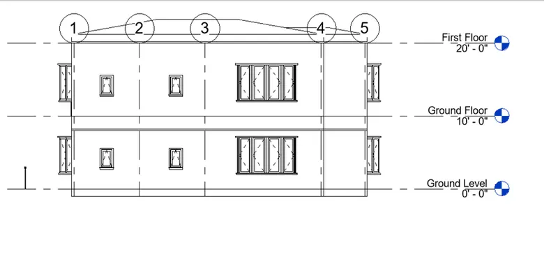
6) Using the elevation tab create the elevation views, looking at your building from East, North, South, and West
AIM :
TO create the elevation views, looking at your building from East, North, South, and West
PROCEDURE :
- Revit excitingly , defaultly given a elevation view in “ELEVATION”
- If you want to create elevation
- Delete the privies views in election
- Go to the “view” tap
- Go to the “ELEVATION”
- Click “ELEVATION”
- Place the “ELEVATION”
- Immediately u will get elevation view in the “PROJECT BROSWER”
- Change the name as “EAST”
- Again to the “VIEW” tap
- Click “ELEVATION”
- Create view as “SOUTH”
- Same as “NORTH AND WEST “
- Once you create a views and finally show the result
RESULT :
EAST VIEW :
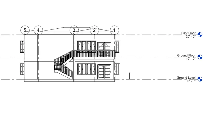
NORTH VIEW :
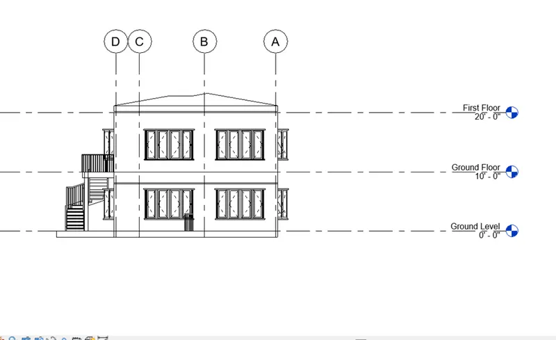
SOUTH VIEW :
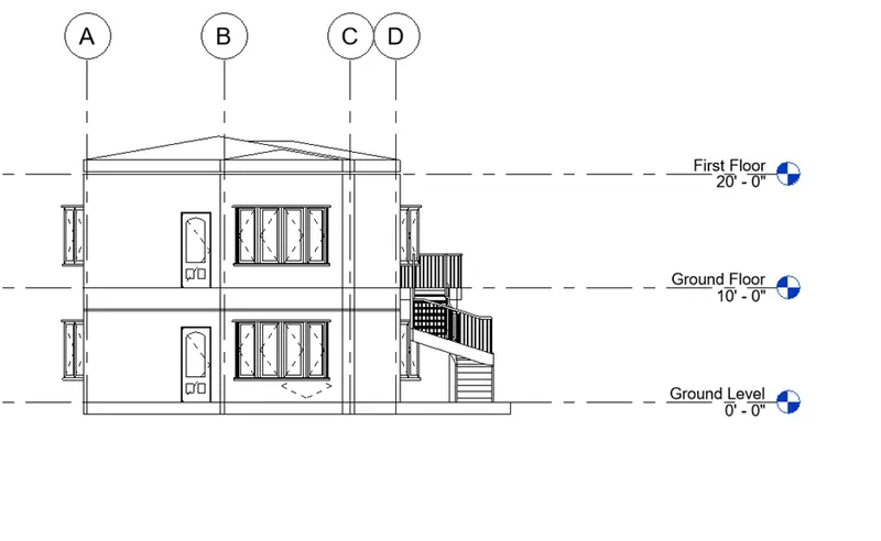
WEST VIEW :
7) Produce section cut through each room either cutting across longitudinally or in a transverse direction
AIM
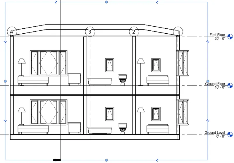
To section cut through each room either cutting across longitudinally or in a transverse direction
Procedure :
- Go to the “REVIT SOFTWARE “
- Open a previse drawing which is already created in the Revit software
- Go to the “VIEW” tap
- Click the “SECTION”
- Give section point and change the name as bedroom, kitchen , toilet , living and mater bedroom
- Create section view for each room and finally show the result
RESULT :
BED ROOM :
KITCHEN VIEW :
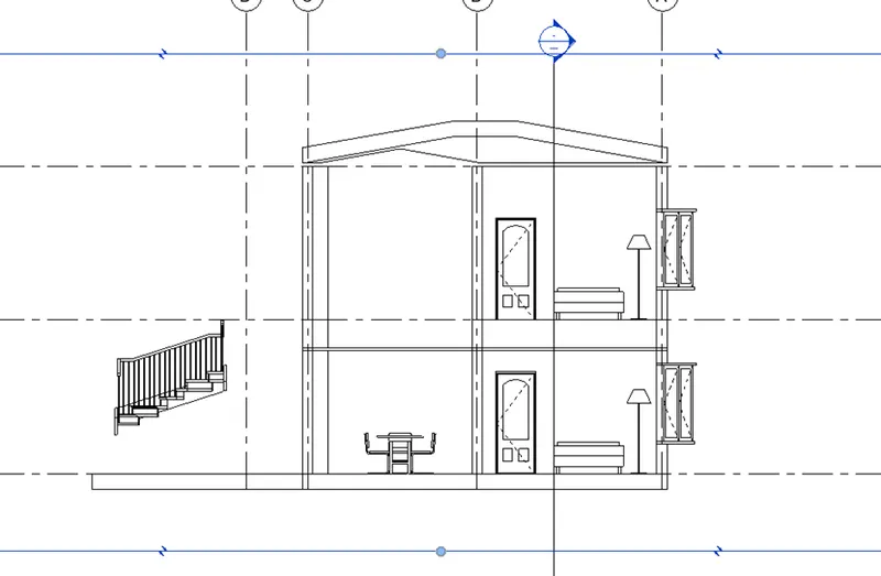
LIVING ROOM VIEW :
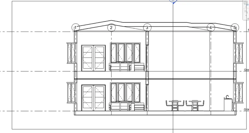
MASTER BED ROOM :
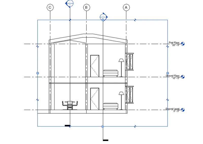
TOILET :
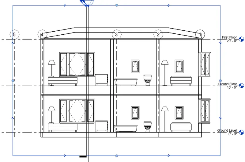
8) Classify the views, Plan Views, Section Views, and Elevation views to either Design or Documentation category using Properties browser
AIM :
To Classify the views, Plan Views, Section Views, and Elevation views to either Design or Documentation category using Properties browser
PROCEDURE :
- We already created the property using Revit software
- Will taking the screen shot of the all view , like plan, section and elevation view
- finally show the result as shown in below
RESULT :
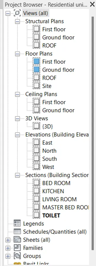
STRCTURAL PLAN :
GROUND FLOOR
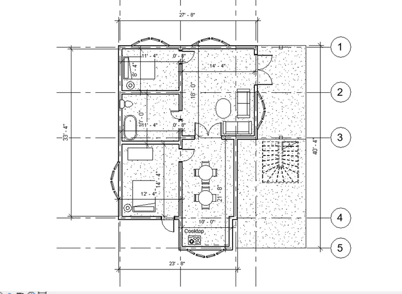
FIRST FLOOR :
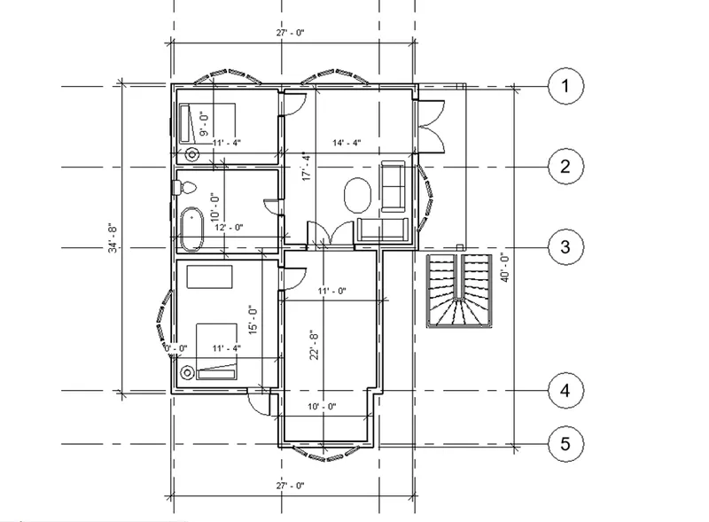
ROOF :
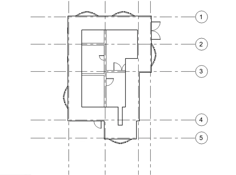
FLOOR PLAN :
Site plan :
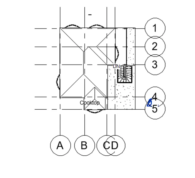
GROUND FLOOR :
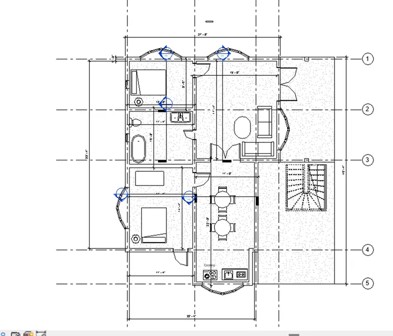
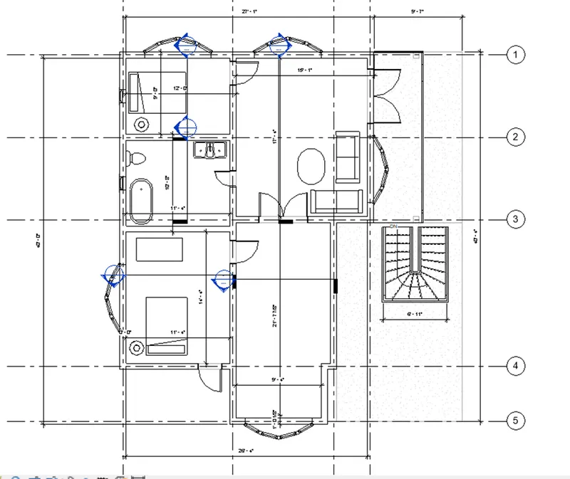
First floor :
Roof :
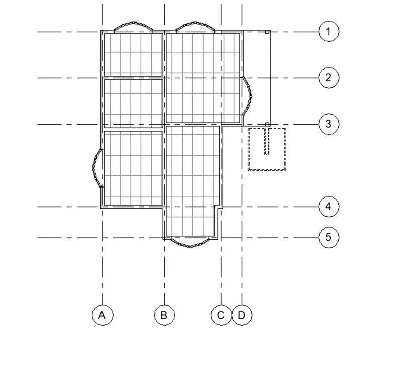
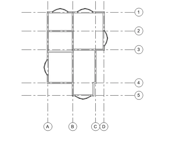
Celling plan :
Ground FLOOR :
FIRST floor :
3D VIEW :
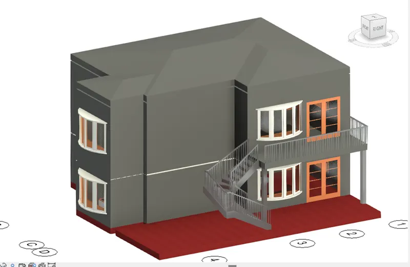
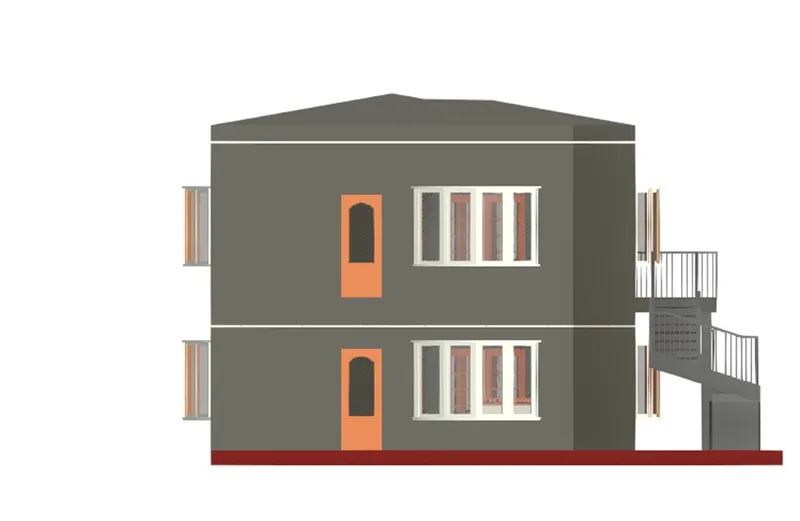
ELEVATION VIEW :
EAST VIEW :
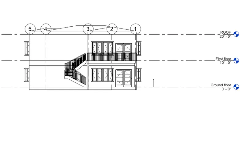
WEST VIEW :
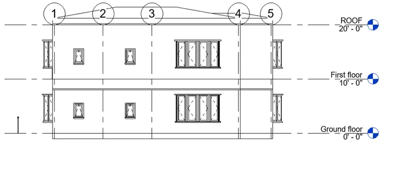
SOUTH VIEW :
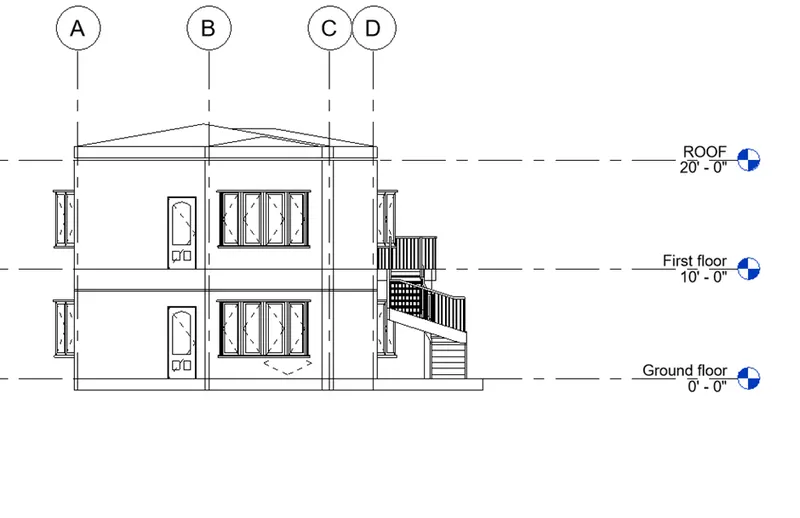
NORTH VIEW :
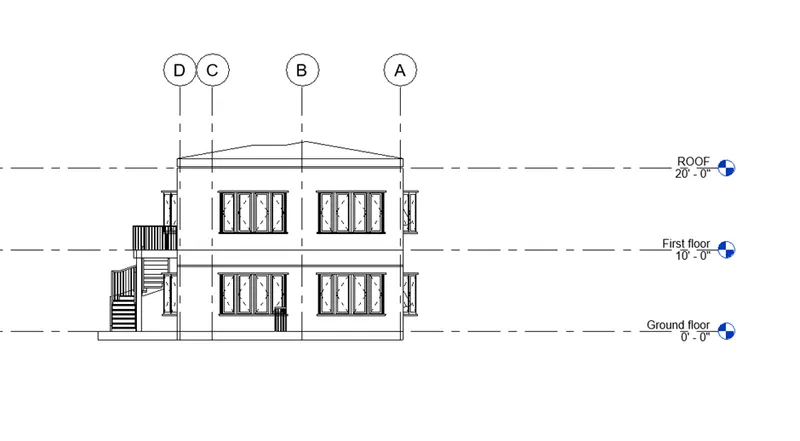
SECTIONS (BUILDING SECTIOR)
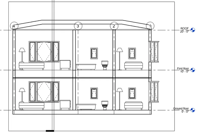
KITCHEN VIEW :
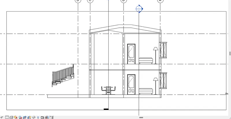
LIVING ROOM VIEW :
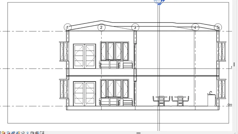
MASTER BEDROOM VIEW :
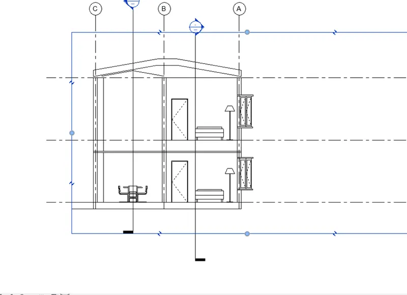
TOILET VIEW :
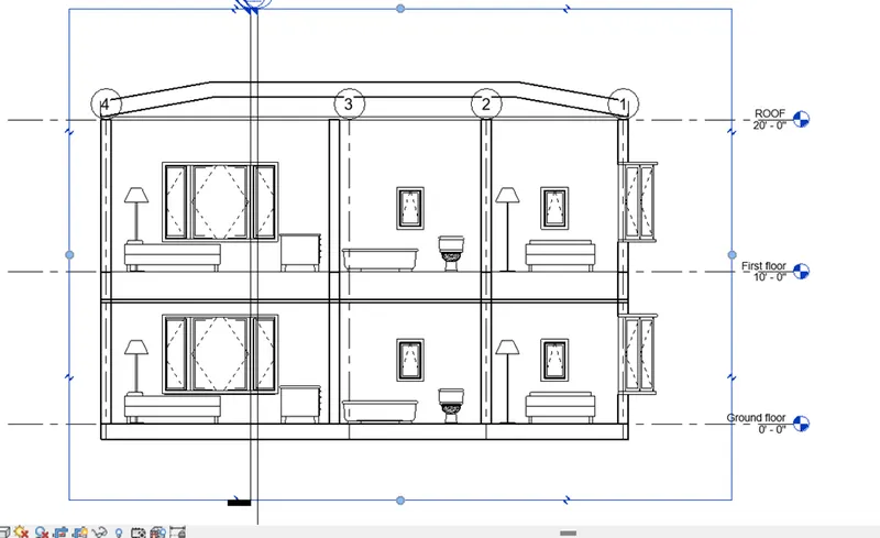
9) Using the sheet template produced create multiple sheets as follows
a. A 101- Ground Floor Architecture Plan
b. A 102- First Floor Architecture Plan
c. A 103- Roof Plan
d. S 101- Ground Floor Structural Plan
e. S 102- First Floor Structural Plan
f. S 103- Roof Framing Plan
g. A-201- North-South Elevations
h. A-202- East-West Elevations
Add additional sheets based on the sections created in your Revit file
AIM :
To create multiple sheet as follows
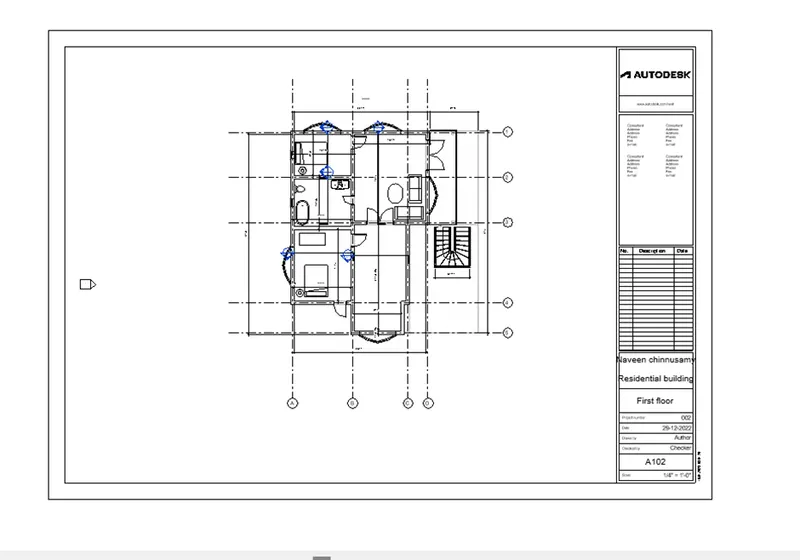
- A 101- Ground Floor Architecture Plan
b. A 102- First Floor Architecture Plan
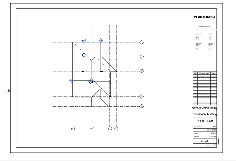
c. A 103- Roof Plan
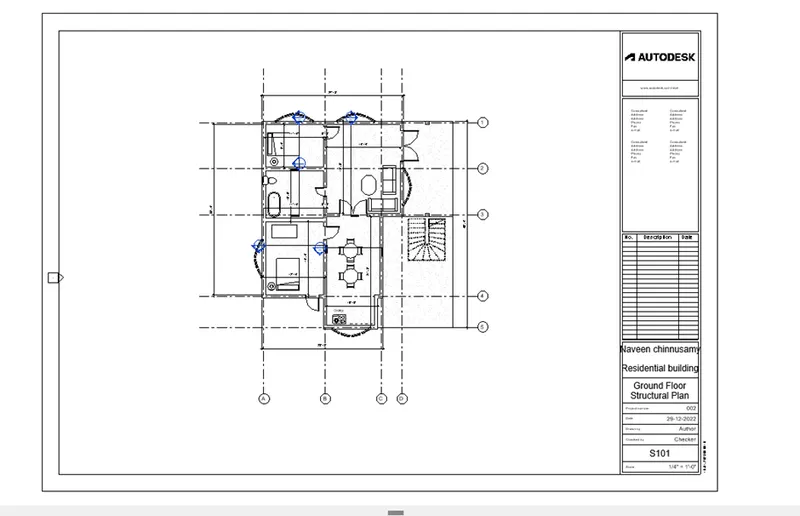
d. S 101- Ground Floor Structural Plan
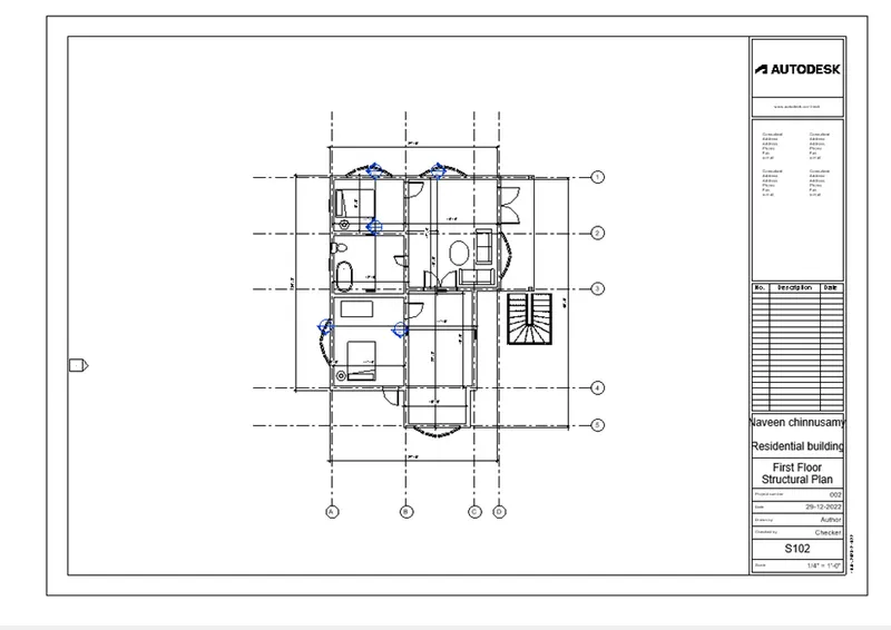
e. S 102- First Floor Structural Plan
f. S 103- Roof Framing Plan
g. A-201- North-South Elevations
h. A-202- East-West Elevations
procedure :
STEP 1:
A 101- Ground Floor Architecture Plan:
- Go to the “view” tap
- Click the “sheet “
- U will get dialog box
- Select the “A1 -METRIC “
- Click “OK”
- Than click “OK”
- Give a rename as “A101 -GROUND FLOOR “ as shown in below .
- Go to the “PROJECT BROWSER”
- Select the “ARCHITECTURE PLAN”
- Select the “Ground floor “DRAWING
- Drag it in the drawing “A101- GROUND FLOOR “ Sheet
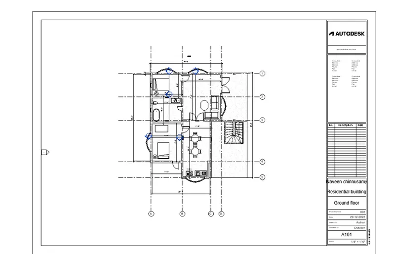
STEP 2:
A 102- First Floor Architecture Plan :
- Go to the “view” tap
- Click the “sheet “
- U will get dialog box
- Select the “A1 -METRIC “
- Click “OK”
- Than click “OK”
- Give a rename as “A102- FIRST FLOOR“ as shown in below .
- Go to the “PROJECT BROWSER”
- Select the “ARCHITECTURE PLAN”
- Select the “FIRST FLOOR“ DRAWING
- Drag it in the drawing “A102- FIRST FLOOR “ Sheet
STEP 3:
A 103- Roof Plan
- Go to the “view” tap
- Click the “sheet “
- U will get dialog box
- Select the “A1 -METRIC “
- Click “OK”
- Than click “OK”
- Give a rename as “A103- ROOF PLAN“ as shown in below .
- Go to the “PROJECT BROWSER”
- Select the “ARCHITECTURE PLAN”
- Select the “ROOF PLAN“DRAWING
- Drag it in the drawing “A103- ROOF PLAN “ Sheet
STEP 4:
S 101- Ground Floor Structural Plan
- Go to the “view” tap
- Click the “sheet “
- U will get dialog box
- Select the “A1 -METRIC “
- Click “OK”
- Than click “OK”
- Give a rename as “S101- ROOF PLAN“ as shown in below .
- Go to the “PROJECT BROWSER”
- Select the “STRUCTURAL PLAN”
- Select the “GROUND FLOOR PLAN“DRAWING
- Drag it in the drawing “S101 -GROUND FLOOR PLAN “ Sheet
STEP 5:
S 102- FIRST Floor Structural Plan
- Go to the “view” tap
- Click the “sheet “
- U will get dialog box
- Select the “A1 -METRIC “
- Click “OK”
- Than click “OK”
- Give a rename as “S102- FIRST FLOOR“ as shown in below .
- Go to the “PROJECT BROWSER”
- Select the “STRUCTURAL PLAN”
- Select the “FIRST FLOOR PLAN“ DRAWING
- Drag it in the drawing “S102 -FIRST FLOOR PLAN “ Sheet
STEP 6:
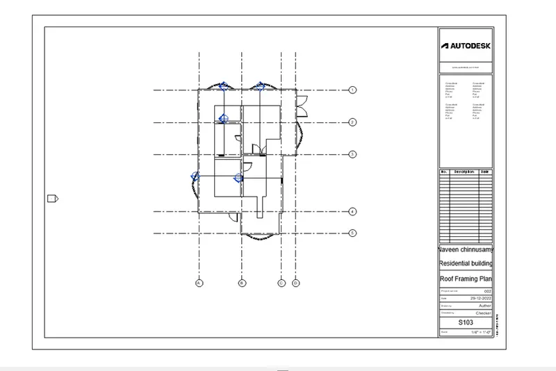
S 103- Roof Framing Plan :
- Go to the “view” tap
- Click the “sheet “
- U will get dialog box
- Select the “A1 -METRIC “
- Click “OK”
- Than click “OK”
- Give a rename as “S103- ROOF FRAMING PLAN“ as shown in below .
- Go to the “PROJECT BROWSER”
- Select the “STRUCTURAL PLAN”
- Select the “ROOF FRAMING PLAN“ DRAWING
- Drag it in the drawing “S103-ROOF FRAMING FLOOR PLAN “ Sheet
STEP 7:
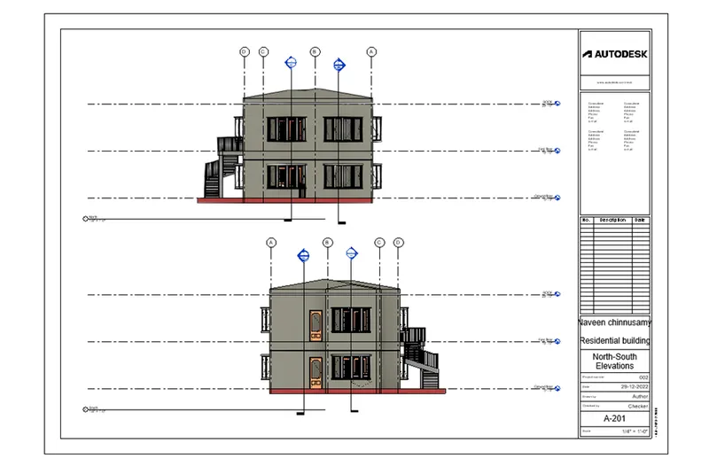
A-201- North-South Elevations :
- Go to the “view” tap
- Click the “sheet “
- U will get dialog box
- Select the “A1 -METRIC “
- Click “OK”
- Than click “OK”
- Give a rename as “A-201- NOTH -SOUTH ELEVATIONS“ as shown in below .
- Go to the “PROJECT BROWSER”
- Select the “ELEVATIONS”
- Drag it north and south elevation on the sheet
- Select the “A-201- NOTH -SOUTH ELEVATIONS “ DRAWING
- Drag it in the drawing “A-201- NOTH -SOUTH ELEVATIONS“ Sheet
STEP 8:
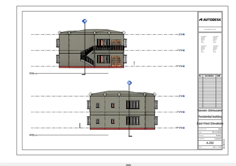
A-202- East-West Elevations
- Go to the “view” tap
- Click the “sheet “
- U will get dialog box
- Select the “A1 -METRIC “
- Click “OK”
- Than click “OK”
- Give a rename as A-202- East-West Elevations
- as shown in below .
- Go to the “PROJECT BROWSER”
- Select the “ELEVATIONS”
- Drag it north and south elevation on the sheet
- Select the “A-202- East-West Elevations DRAWING
- Drag it in the drawing A-202- East-West Elevations Sheet
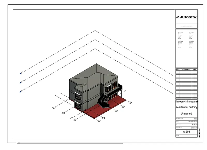
10) Create a camera-specific view or a 3D view in each room ( living, dining, bedroom). Based on the views create a new set of sheets starting A-501 (you can add as many sheets after, 502, 503.. n)to place the 3D view images. Produce the sheets as a part of project drafting.
AIM:
To create camera -specific view or 3d view in each room (living, dining , bedroom )
Procedure
STEP 1:
- We already created property using Revit software
- Go to the “VIEW” tap
- Then go to the “3D VIEW “
- Select the camera “
- Go to the floor plan ,
- Fix the camera each room , room (living, dining , bedroom )
- Change the camera name as (living, dining , bedroom ) as per the drawing
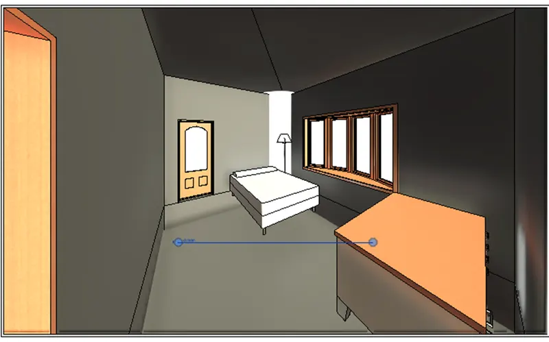
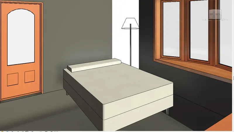
BED ROOM VIEW :
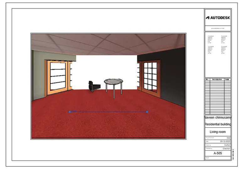
LIVING ROOM VIEW :
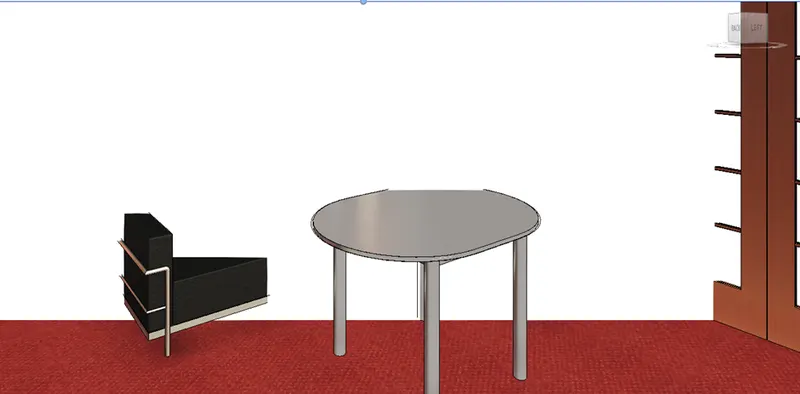
(NOTE : there is some technical error )
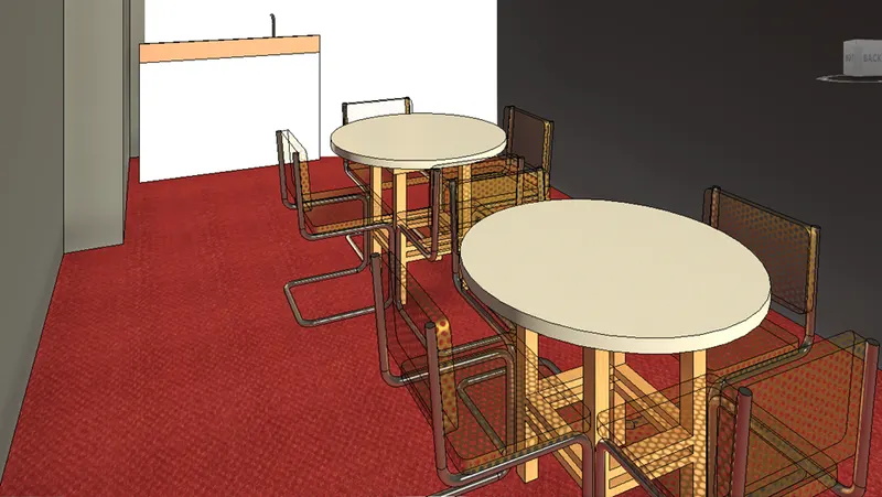
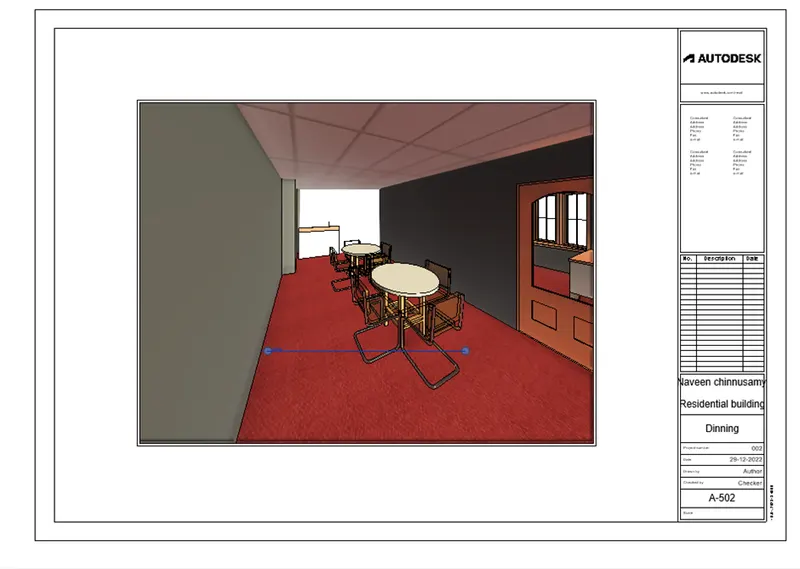
DINNING ROOM :
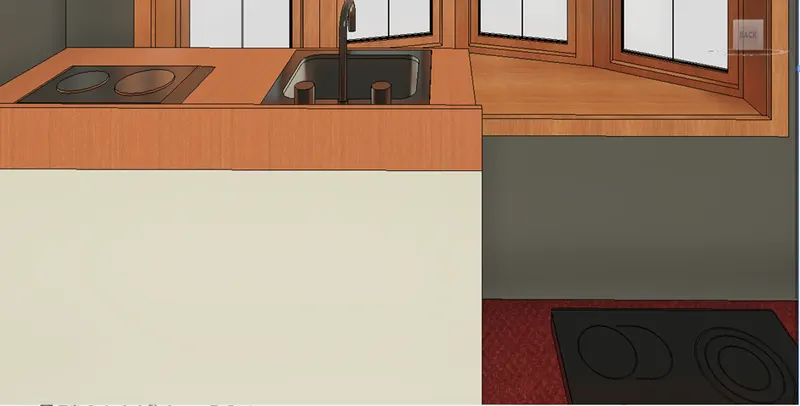
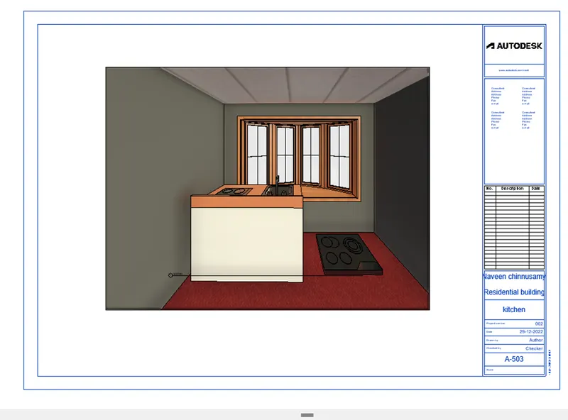
KITCHEN :
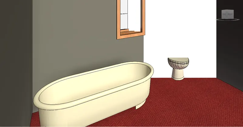
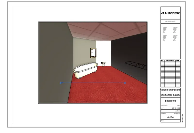
BATH ROOM :
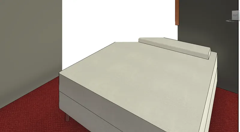
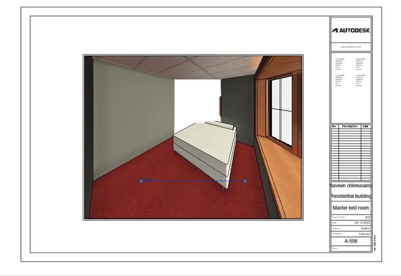
MASTER BED ROOM:
STPE 2:
- Go to the “VIEW” tap
- Click the “sheet”
- U will get dialog box
- Select the “A1-MATERIC”
- Change the name as (A-501 , A-502 for all the room )
- Darg it the created view in the sheet
- U will get a tap called “MODIFY / VIEW PORT”
- Change the size of the pic as per your requirement
- Finally show the result
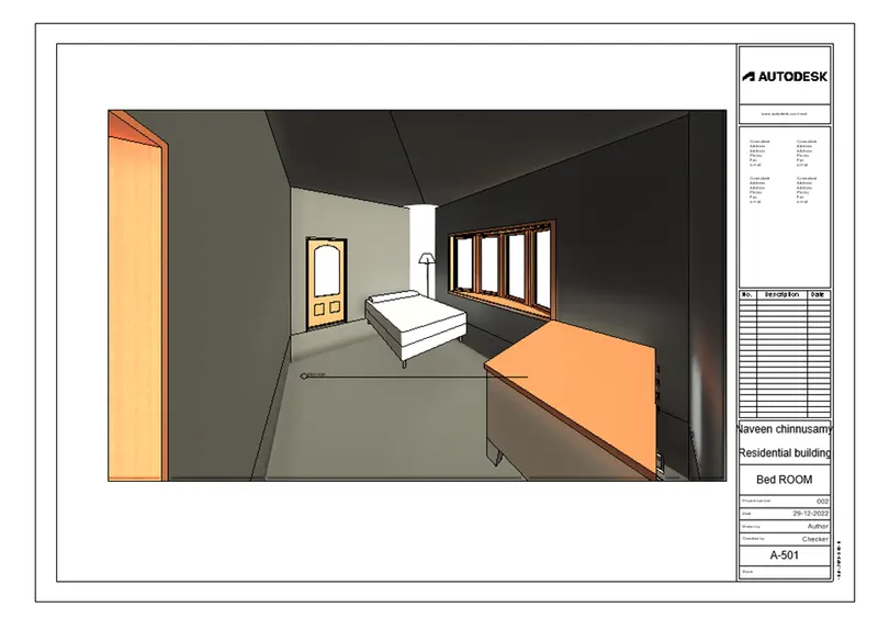
RESULT :
Bed room:
Dinning :
Kitchen :
Bath room :
Living room :
Master bedroom :
NOTE:
I’m working professional , that’s why it’s take more time to submit the challenges , kindly accept my request , help me to improve my career and knowledge
Thank you.