3D Creation of Celing, Roof, Architectural plan, Structural plan, Sectional view, Elevation view and Camera specific view for a house plan using REVIT
1) Based on the project saved from Week 3, proceed from the First Floor Level. Model a Ceiling from the architecture tab above the walls at the first-floor level
Aim: To model a Ceiling from the architecture tab above the walls at the first-floor level
Introduction: The modelling of ceiling plays an important in creation of building model. It acts as a top of each floor level and as a floor for the top floor level for eg: the ceiling of ground floor acts as a floor for the first floor as it is provided at the top of ground floor which is the first floor level.
Steps:
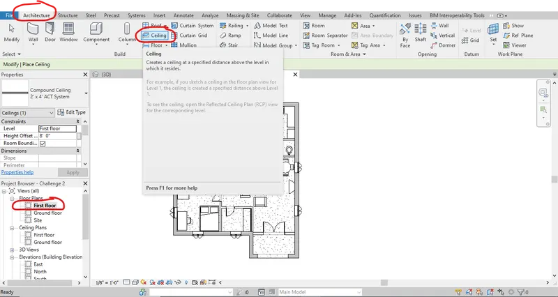
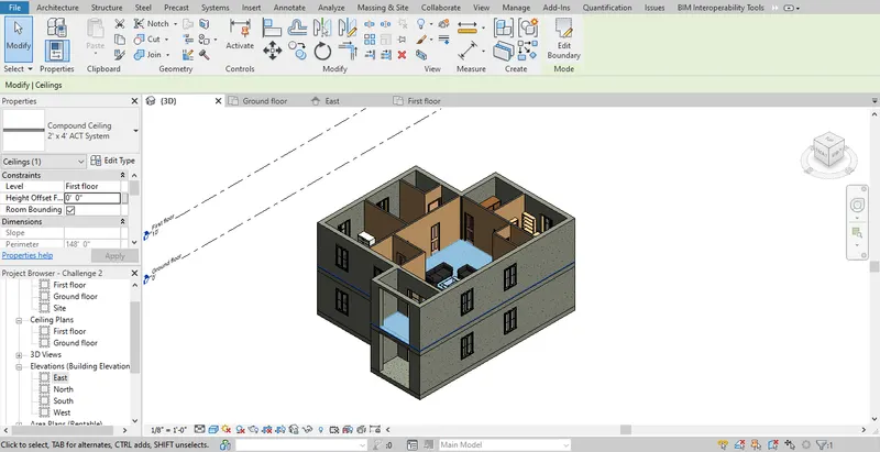
- Initially the option ceiling is selected from the architecture tab in the ribbon
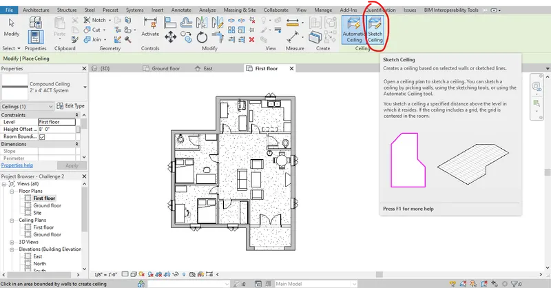
- Then sketch ceiling option is selected in the ribbon tab
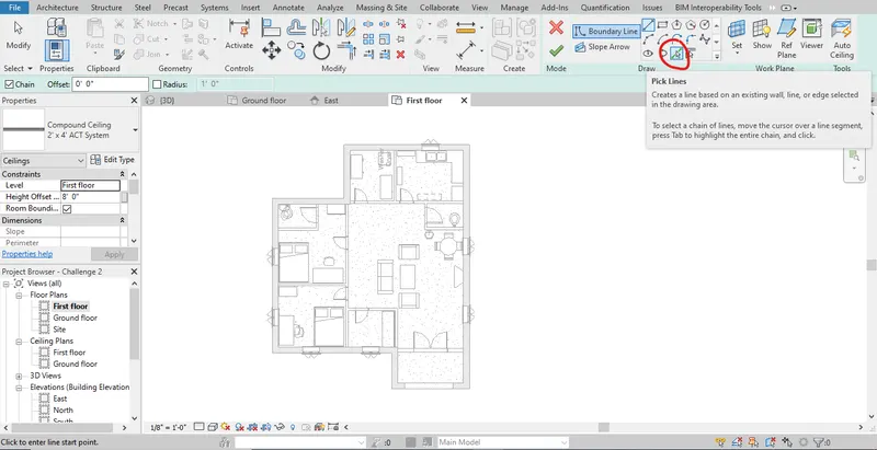
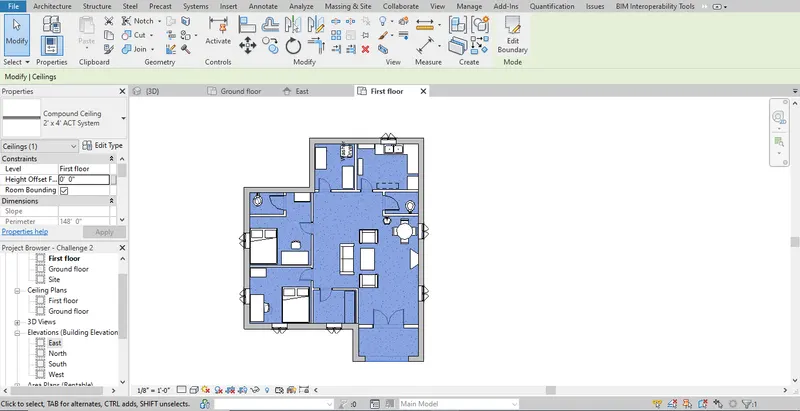
- Furthermore using pick line tool the external walls are selected carefully and the ceiling is created at the first floor level
Results: Thus a ceiling is modelled sucessfully at the first floor level.
2) Model a roof above the ceiling by selecting the footprints of the ceiling. Using the adjustment toolbars appearing on-screen adjust the roof slope to 10 degrees
Aim: To model a roof above the ceiling and to set the roof slope to 10 degrees.
Introduction: The modelling of roof is the last step in modelling which completes the top of the structure. Roof is one of the vital model component provided in the building model which covers the top of any structure and different types of roof are available for modelling.
Steps:
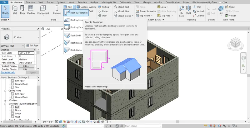
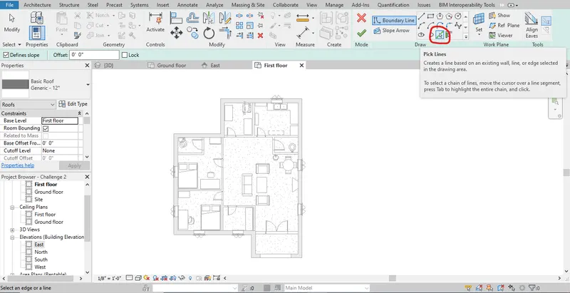
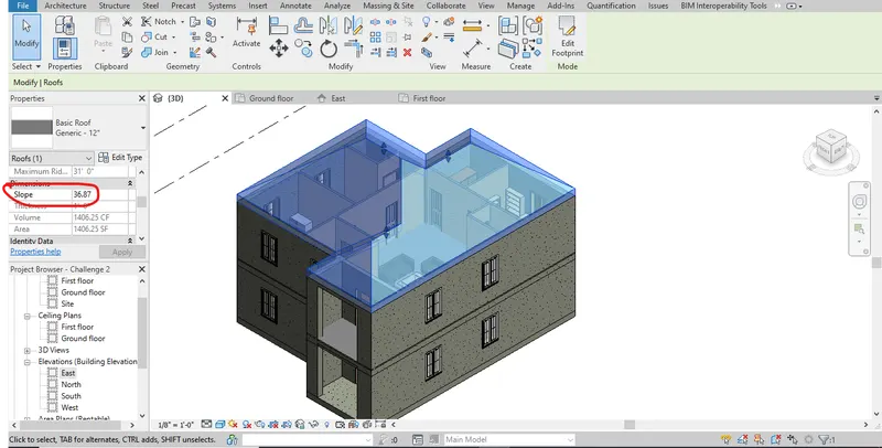
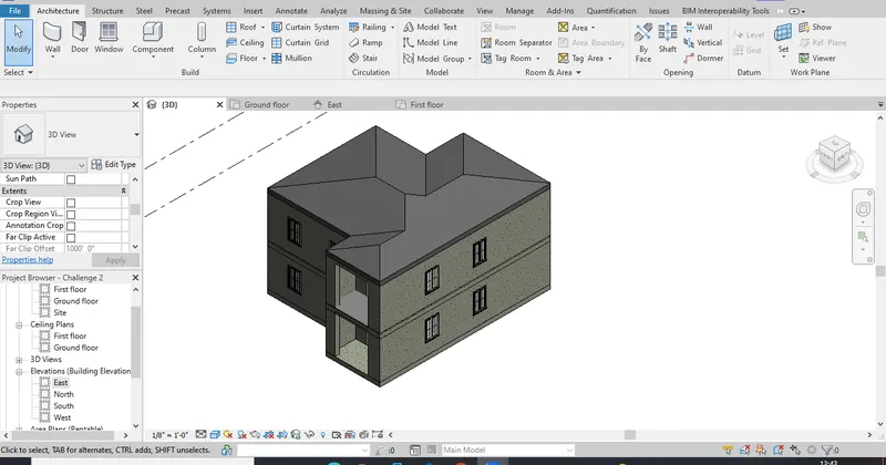
- For providing roof to the model, roof option is selected from the architecture tab in the ribbon
- Then roof by footprint option is selected
- Followed by that pickline tool is selected and the external wall lines are selected carefully and the roof is created
- To provide changes in the roof properties browser is used.
- In the properties browser the slope of the roof is changed to 10deg and the same is applied in the model.
Results: Thus a roof is modelled sucessfully and the corresponding slope is set to 10deg.
3) Using the file saved from weeks 2 to 4, create plan views for ground floor level and first-floor level including all the walls, floors, and components. Separate them to
architecture and structural plans
a. Architecture plan must have walls, floors, and all the components placed within the building
b. Structure plan must have details of only walls, floors, and columns
Aim: To create plan views for ground floor level and first-floor level including all the walls, floors, and components and to separate them to architecture and structural plans.
Introduction: In every building model there are always different kinds of plans are based on their discipline of work involved in the particular building model. Predominantly two plans are important for any structure which is Architectural plan and structural plan. All plans contains the same building model but the difference of each plan is that they contain the elements which are their respective disciplines for eg: the architectural plan consists of every details such as furniture elements also whereas, the stuctural plan only consists of building elements such as beam,column,walls etc.,
Steps:
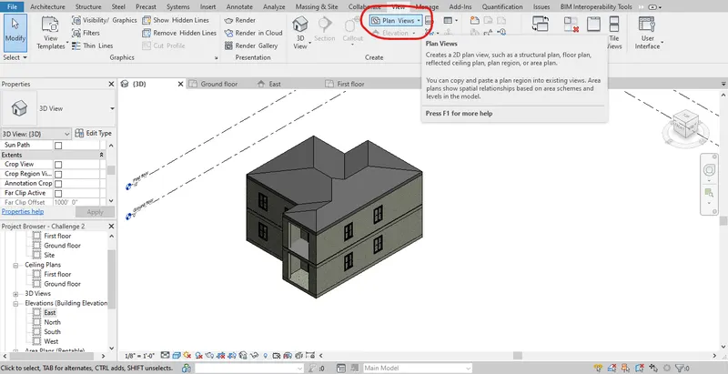
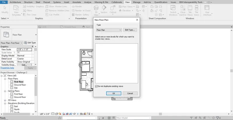
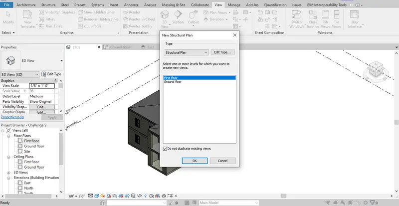
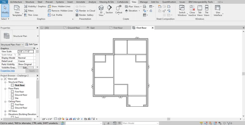
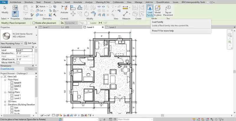
- For providing plan views, In the view tab planviews option is selected from the ribbon
- Then in that diiferent options are available such as Plan view and Structural view
- Initially structural view is selected and the corresponding structural view of the model is generated for both floors
- Followed by plan view for the model created
Results: Thus architectural and structural views for corresponding floors are created sucessfully for the building model.
4) Using annotate toolbar add dimensions to all the walls and floors with reference to the longitudinal and transverse grids created in the project file
a. The architecture plan dimensions include details on where the components are placed within the buildings with relation to grids. Overall dimensions are sufficient for architecture plans
b. The Structure plan dimensions must include details on the position of all the walls and interior walls with reference to grids. Locate all the framing components of the building with reference to a fixed point using Structural plans
Aim: To provide dimensions to the corresponding architectural and structural plan views using annotate tab.
Introduction: The process of providing dimensions to the model created is of vital importance. Dimensions provide the exact picture about the model to be created in the field. It is also helpful in placing the components at the perfect positions of the building model to be built.
Steps:
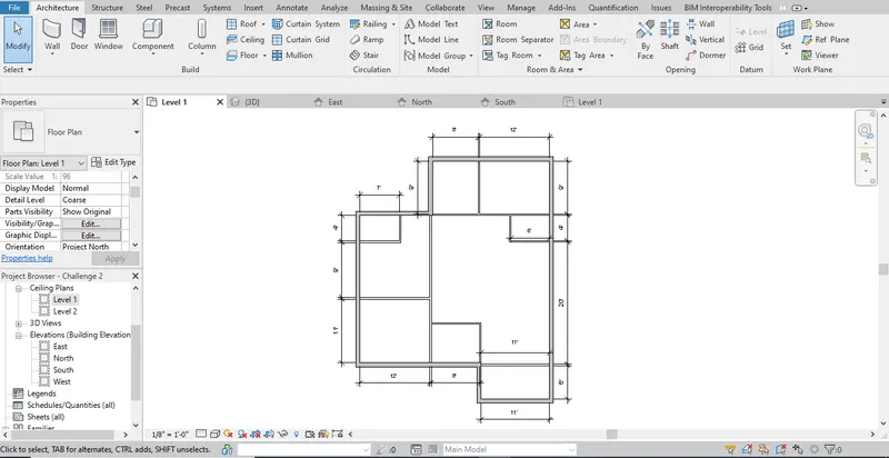
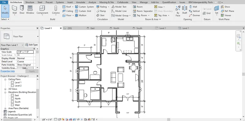
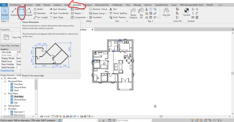
- For providing dimensions, annotate tab is selected
- Then using the tool linear dimensions are provided by selecting the end to end of the wall which is to be given dimension
- Any component is provided dimension using linear or aligned by selecting from end to end of the specific component
Results: Thus dimensions are provided in the architectural and structural plan views sucessfully.
5) Create a sheet template from the view tab and adjust the parameters on the sheet to add appropriate views
Aim: To create a sheet template from the view tab and to adjust the parameters on the sheet to add appropriate views
Introduction: The process of presenting the model is the last step in a project. It is done by creating a sheet template of required paper sizes. The sheet template consists of project information such as client name, address and other information regarding administration such as model drawn by and approved by. The information is either entered in the sheet template or by providing project information under the manage tab.
Steps:
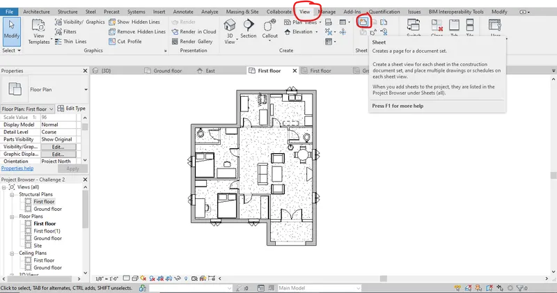
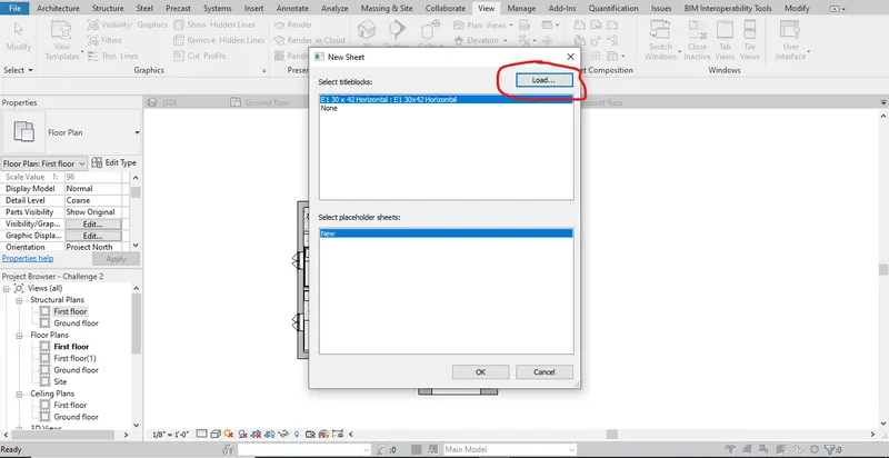
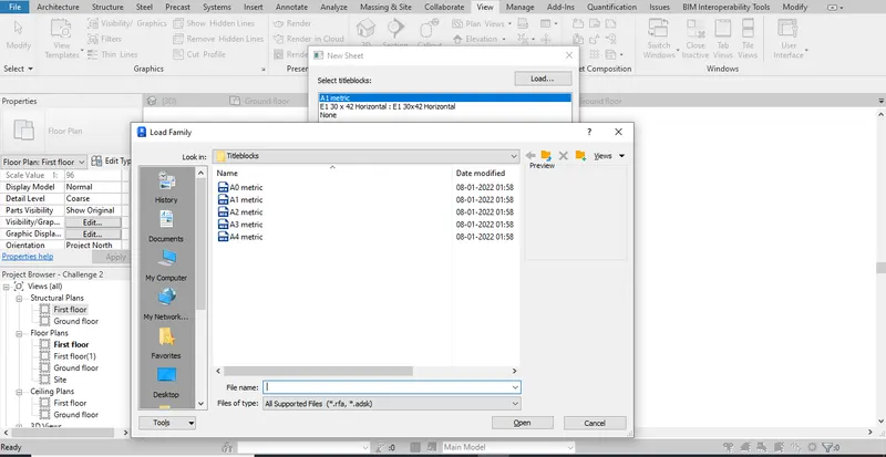
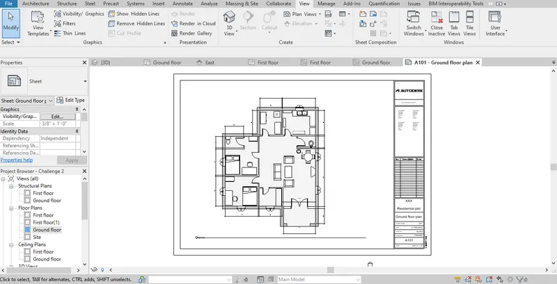
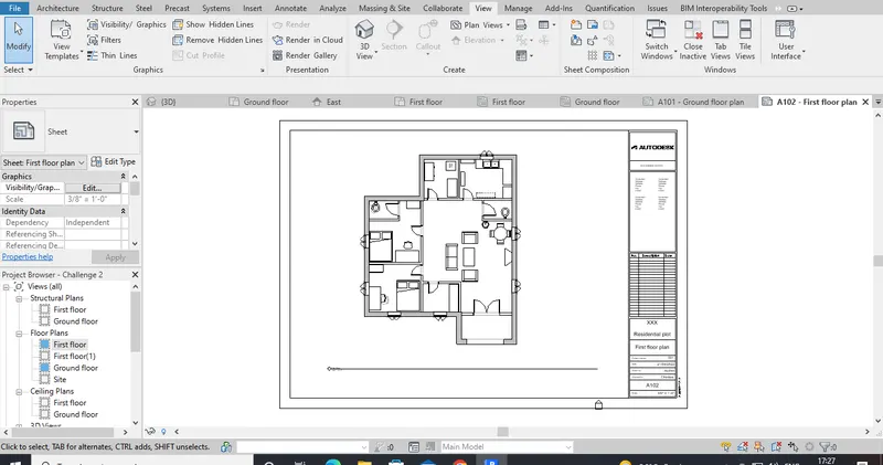
- For creating sheet template sheet option is selected from view tab in the ribbon
- After selecting the sheet option different types of sheet can be selected from the load option
- By selecting the load option family folder is loaded in which titleblock family is selected and A1 sheetset is selected
- After selecting that, it is loaded in the screen and the different types of view can be added to the corresponding sheet template by dragging the required view from the project browser from the left .
- The corresponding sheet can be renamed after the corresponding views placed in the sheet from the project browser or by editing in the sheet itself.
Results: Thus a sheet template is created and the views are inserted sucesfully.
6) Using the elevation tab create the elevation views, looking at your building from East, North, South, and West
Aim: To create elevation views of the model by using the elevation tab in the given directions.
Introduction: For providing a more clear picture about the model, providing different types of the views of model is mandatory. Among the different types of view elevation view is one of the important views of the model created as it provides a clear image of the rise of the building of the structure to be created from the ground level in various directions (North,South,West,East).
Steps:
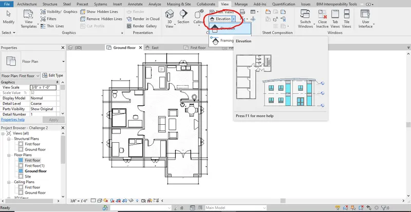
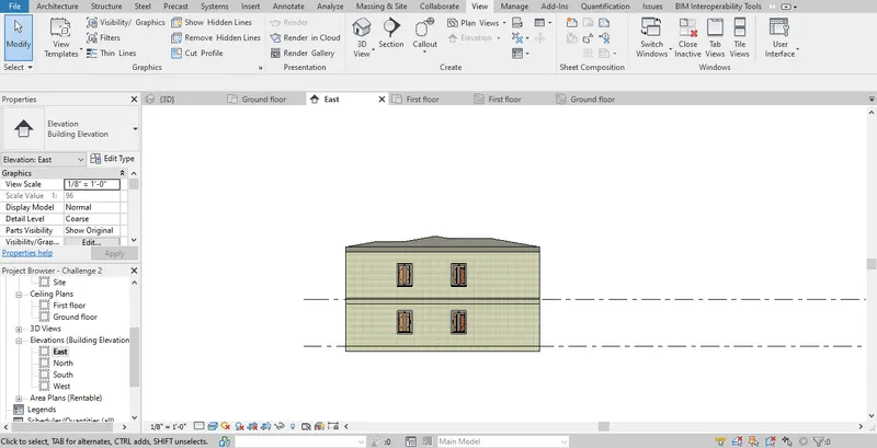
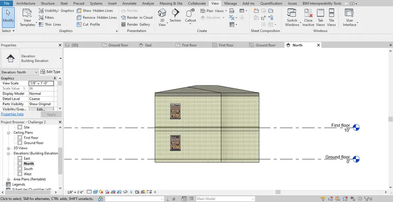
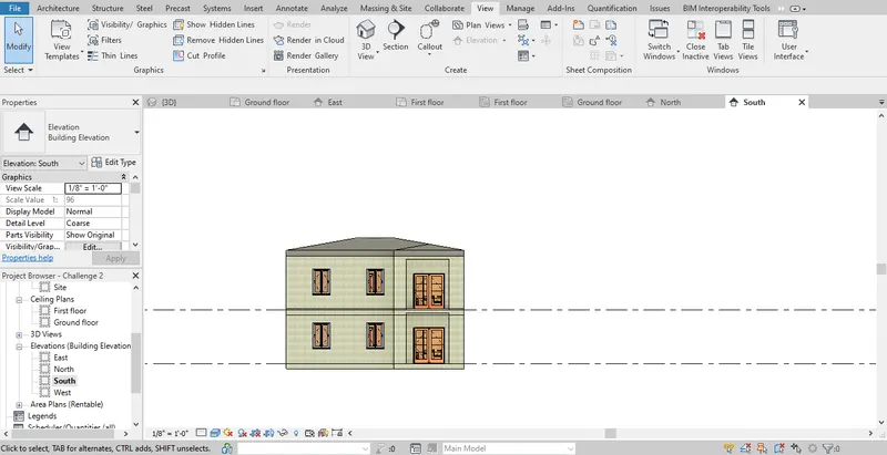
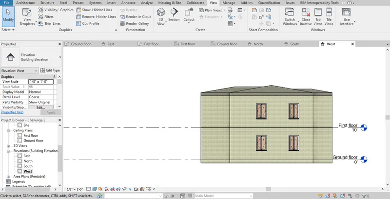
- Initially elevation option is selected from the view tab in the ribbon
- After selecting the elevation option a triangle cursor is to be placed on the model view in the required directions
- It is selected each time and the cursor is placed in the four mandatory directions and the views are created.
- The views can be renamed as per the requirement from the project browser.
Results: Thus the elevation views of the model are created sucessfully.
7) Produce section cut through each room either cutting across longitudinally or in a transverse direction
Aim: To produce section views of each room of the building model created.
Introduction: The need for producing section views is to have better understanding of the model created. It gives us a more clear picture of the elements will be in model in the particular rooms.
Steps:
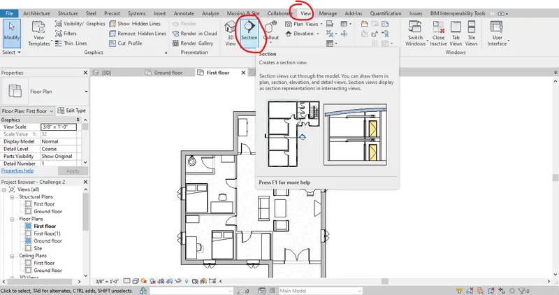
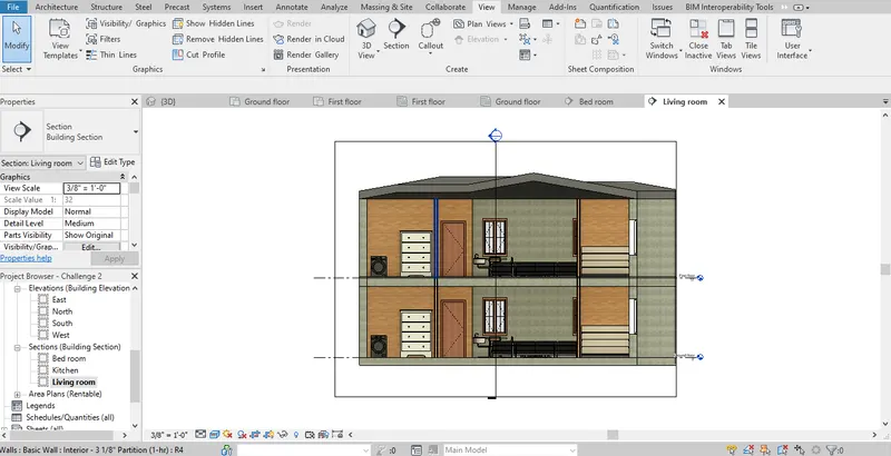
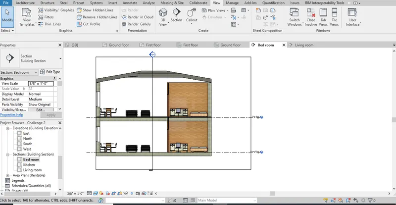
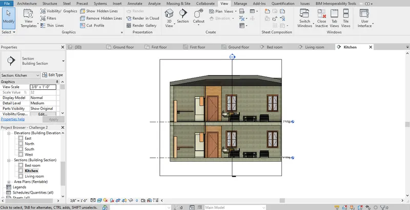
- For providing section views initially section option is selected from the view tab in the ribbon
- After selecting the section option, the cursor can be placed in the model in the required direction and the boundary of the section view can be placed
- The section can be placed and can be changed to the required orientation
- It can also be renamed in the project browser
Results: Thus section views of different rooms are created sucessfully.
8) Classify the views, Plan Views, Section Views, and Elevation views to either Design or Documentation category using Properties browser
Aim: To classify the views, Plan Views, Section Views, and Elevation views to either Design or Documentation category using Properties browser
Introduction: In the process of creating a building model creation of different types of views are of vital importance. To produce more information about the model to the field persons who construct the building it is mandatory to produce different views of the model so as to get a clear picture about the model and to avoid confusion of the elements which are needed to be replicated on the field.
Steps:
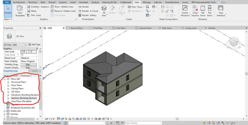
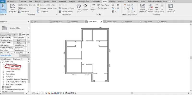
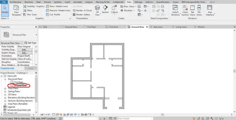
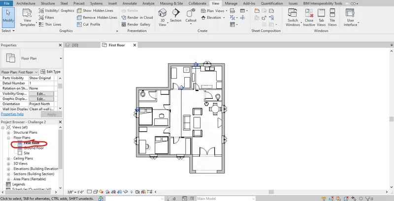
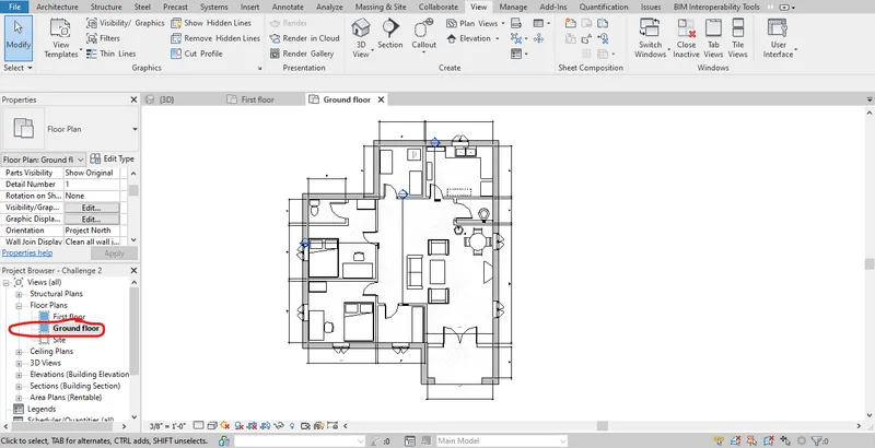
- For providing differnt type of views initially they are created from the view tab in the ribbon and some of the views such as floor plans are created automatically when the model creation is started.
- The differnt views created for the model are loaded in the project browser in the left
- Then for viewing the particular view it is selected from the prjiect browser by double clicking on the particular view needed and it is loaded on the screen.
- In this all the views created for the model are loaded and submitted
Results: Thus different types of view such as Plan Views, Section Views, and Elevation views of the model are submitted sucessfully.
9) Using the sheet template produced create multiple sheets as follows
a. A 101- Ground Floor Architecture Plan
b. A 102- First Floor Architecture Plan
c. A 103- Roof Plan
d. S 101- Ground Floor Structural Plan
e. S 102- First Floor Structural Plan
f. S 103- Roof Framing Plan
g. A-201- North-South Elevations
h. A-202- East-West Elevations
Add additional sheets based on the sections created in your Revit file
Aim: To present the different types of plan and elevation views etc., in multiple sheet templates.
Introduction: After creating different types of views for the model it is mandatory to present them in a right mannner to avoid confusion of the different views of the model. Hence, each view of the building model is presented in multiple sheet templates with their view as the name for the particular sheet.
Steps:
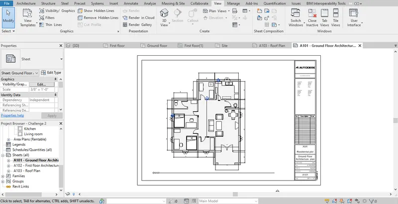
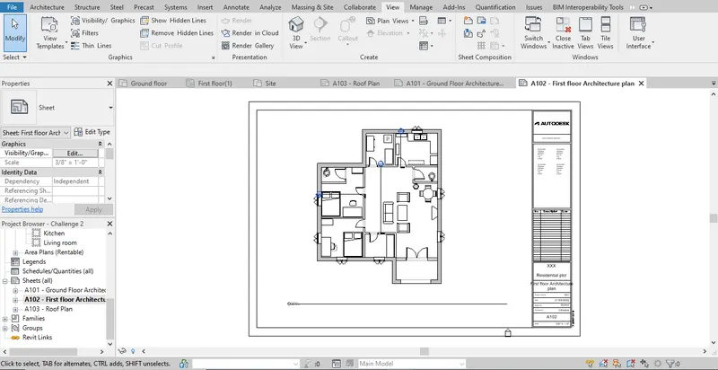
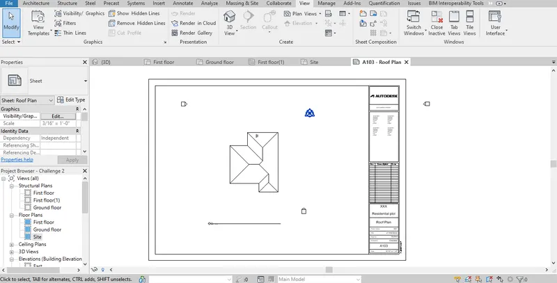
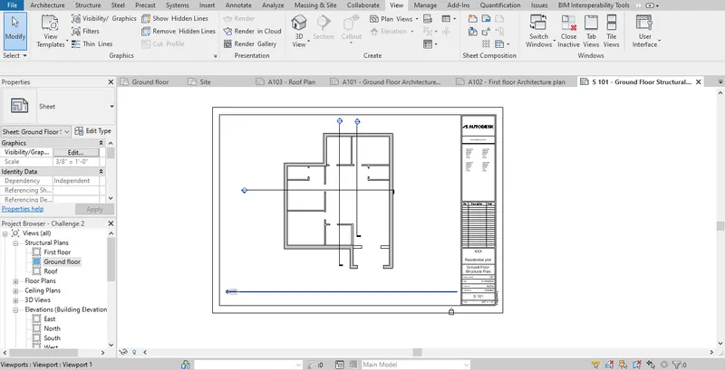
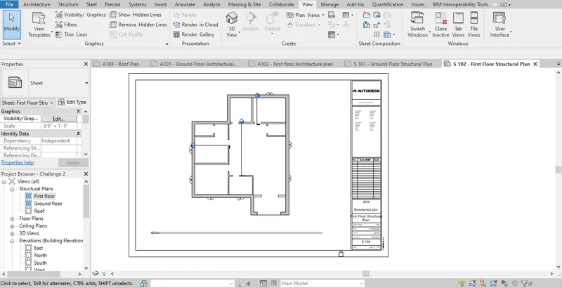
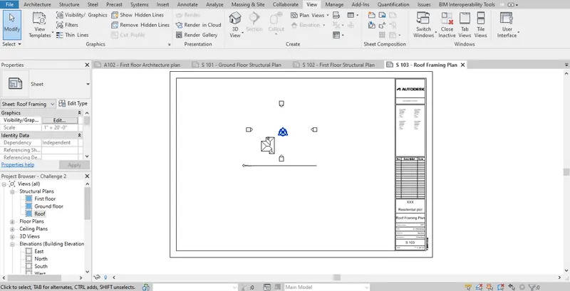
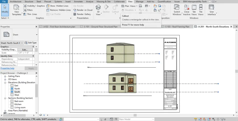
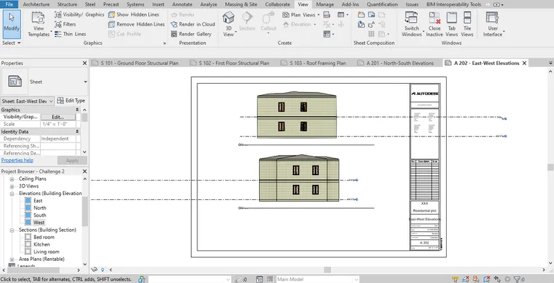
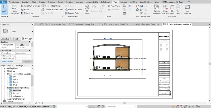
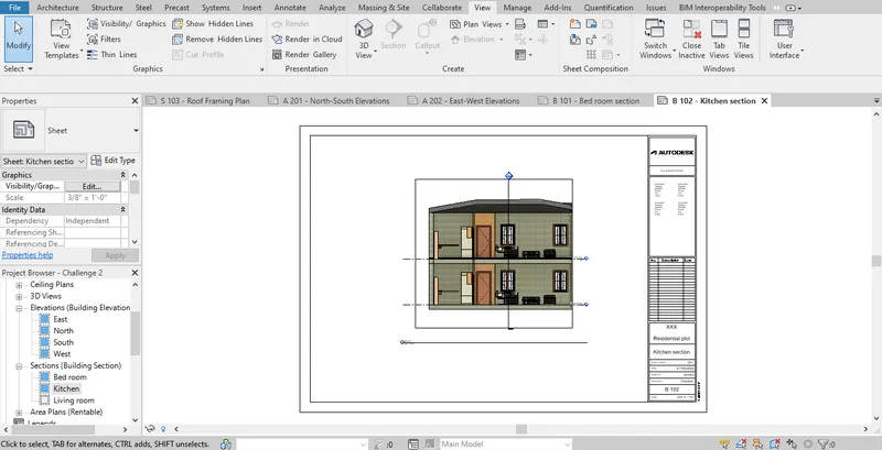
- Initially sheet template is created by selection sheet option from the view tab
- Then the required sheet is loaded in the screen
- Then the views are inserted into the sheet template by dragging the required view from the project browser using the mouse
- Then the sheet template can be renamed either by the project browser or in the sheet template itself by double clicking on it
- The same process is continued for adding all the required views in the sheet templates.
Results: Thus all the views are added to the multiple sheet templates and are renamed sucessfully.
10) Create a camera-specific view or a 3D view in each room ( living, dining, bedroom). Based on the views create a new set of sheets starting A-501 (you can add as many sheets after, 502, 503.. n)to place the 3D view images. Produce the sheets as a part of project drafting.
Aim: To create a camera-specific view or a 3D view in each room and to add the camera views in multiple sheet templates.
Introduction: In the process of BIM , the mandatory objective is to give clear information about the model to the clients. In order to provide more specific information about the model camera views are created which gives the more realistic images of the model to be constructed and the camera views are created for another main purpose which is rendering which will give the original image of the model to be constrcuted. The camera views can be created as per the requirement and can be placed inside the model wherever needed.
Steps:
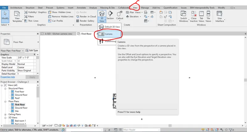
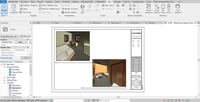
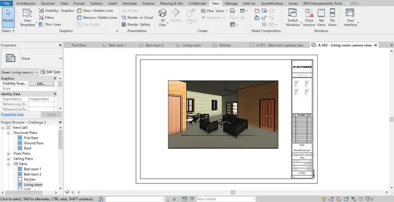
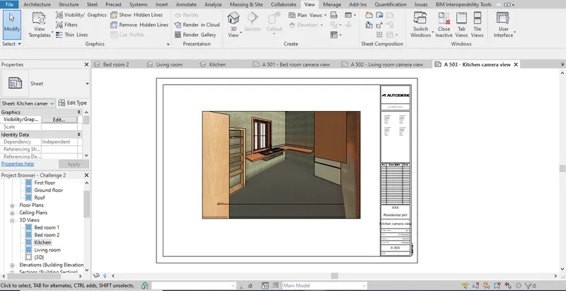
- The creation of camera views can be done from the camera option in the 3d command of the view tab in the ribbon
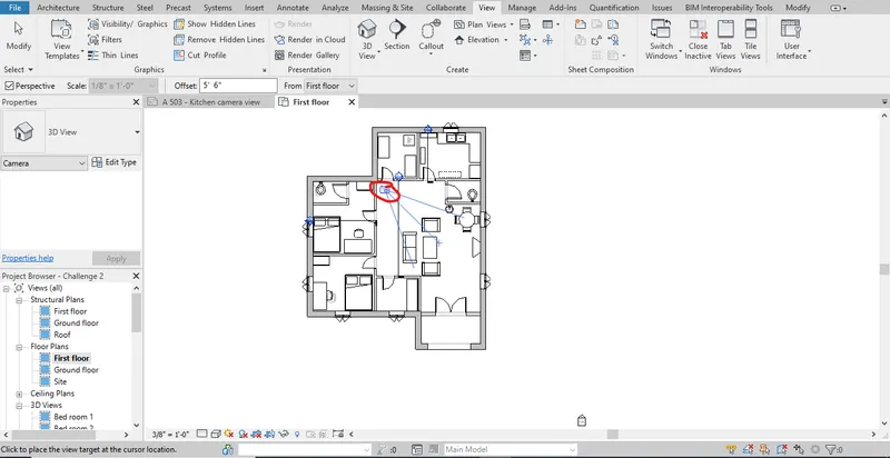
- After selecting the camera view, a camera like cursor appears and it can be placed in the model wherever in the model as per the requirement and the view can be set using the mouse after placing the camera
- Then after fixing the view it is created and can be renamed in the project browser under the 3d views column
- The process is continued for other rooms to have camera views for each rooms
- Then under the same view tab using sheet option, sheet templates are created and the camera views are placed in the sheets
- It can be renamed either in the project browser or in the sheet template as per the views named.
Results: Thus different camera specific views are created for each rooms and are placed in the sheet templates for presentation sucessfully.