3D Creation of Celing, Roof, Architectural plan, Structural plan, Sectional view, Elevation view and Camera specific view for a house plan using REVIT
1)
AIM:
To model a ceiling to the previously created project with the help of an architectural tab above the walls at the first-floor level.
TOOLS USED:
Architecture tab
Ceiling
Sketch ceiling
Pick lines
Properties.
PROCEDURE:
- In the project file saved for week 3, click on the ceiling tool in the architecture menu.
- Click on sketch ceiling and boundary by using the pick lines option and click on finish edit option.
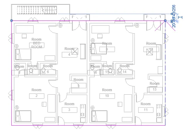
- Set the level up to which we need ceiling level 1 in this case.
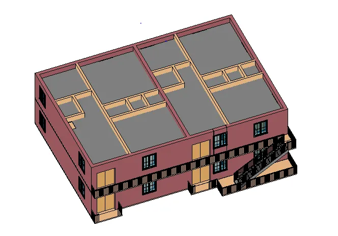
RESULT: The ceiling has been added successfully.
2)
AIM: To model a roof above the ceiling by selecting the footprint of the ceiling and using adjustment toolbars appearing on the screen adjust the roof slope to 10 degrees.
TOOLS USED:
Architecture tab,
ROOF,
Pick lines,
Properties,
slope.
PROCEDURE:
- In the architecture tab, click on the roof by footprint in the roof dropdown.
- Set the boundary for the roof using pick lines options, and click on the finish edit option.
- In the properties of roofs, change the slope to 10 degrees and click apply.
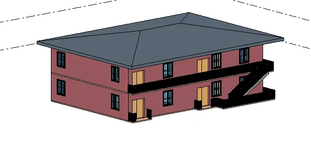
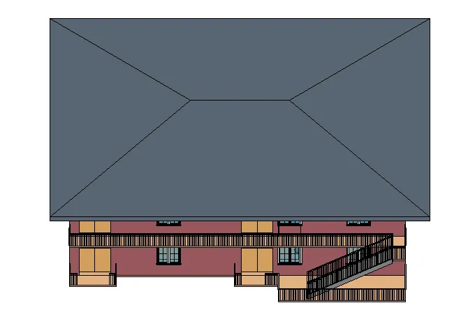
RESULT: The ceiling with 10 degrees is successfully added.
3) AIM: To create a plan view for the ground floor level and first-floor level including all the walls, floors, and components.
TOOLS USED:
Property browser,
Floor plans.
PROCEDURE:
- In the project browser we get plan views on the left side, they are architectural plan views.
ARCHITECTURE PLAN
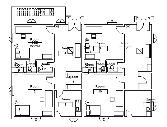
- In the view tab, click other n structural plan view the n plan view drop down to create a structural plan view.
STRUCTURAL PLAN
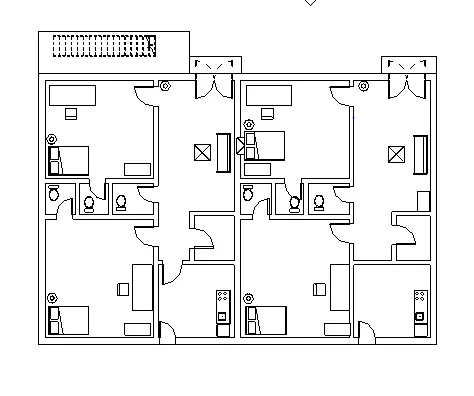
RESULT: The required plan views are obtained.
4) AIM: Add dimensions to walls and floors concerning longitudinal and transverse in a project file.
TOOLS USED:
Architecture
Annotate
Aligned
PROCEDURE:
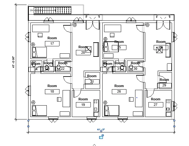
- In the architecture floor plan gives to aligned annotated lines are inducted to the architecture floor plan.
ARCHITECTURE FLOOR PLAN
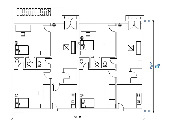
- In the structural floor plan given the aligned annotate lines are inducted into the structural floor plan.
STRUCTURAL FLOOR PLAN
RESULT:
The required architectural and structural plan aligned lines indicated.
5)
AIM: To create a sheet template from the view tab and adjust the parameters on the sheet to add appropriate views.
TOOLS USED:
View
Sheets
Project Browser
PROCEDURE:
- In the view tab, click on sheets and click on A1 METRIC and click ok.
- Then make the required change to the detail sheet by using the project browser.
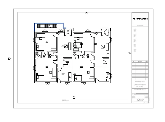
RESULT: The required sheets with parameters are obtained.
6)
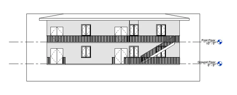
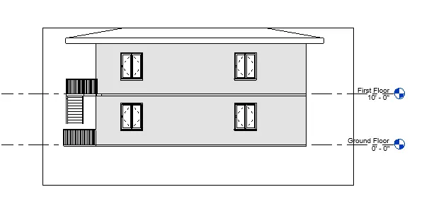
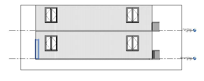
AIM: To use the elevation tab to create the elevation views, look at your building from EAST, NORTH, SOUTH, and WEST.
TOOLS USED:
View
Elevation
Project Browser
PROCEDURE:
- In the view tab, click on the elevation tool.
- On the 4 sides of the drawing, add the elevation logo that appears.
- In the project browser, there will be 4 views named north, west, east, and south. double click on the required view to open it.
EAST
NORTH
SOUTH
WEST
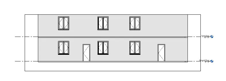
RESULT: The 4 required elevation views are obtained.
7)
AIM: To produce a section cut through each room either cutting across longitudinally or in a transverse direction.
TOOLS USED:
View
Section
Property browser
PROCEDURE:
- In the view menu, click on the section tool.
- Draw the sectional line to get the view wherever sectional view is required.
- In the project browser we find sectional views, double click on the required sectional view to open it.
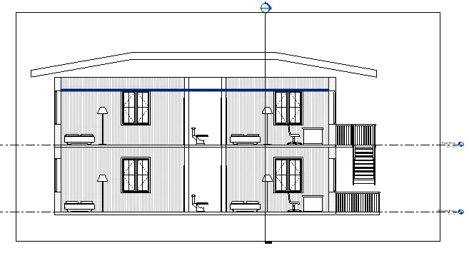
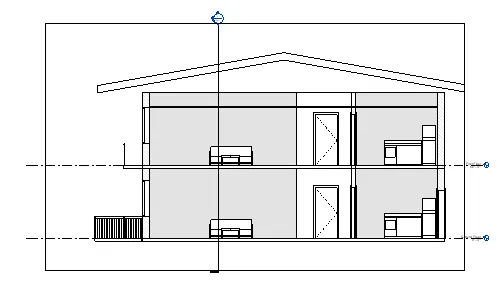
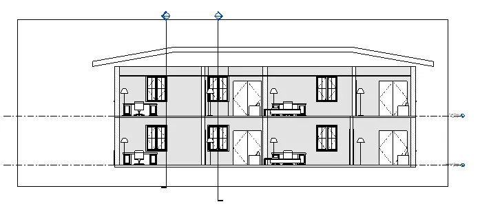
RESULT: The required sectional views and one longitudinal are obtained.
8)
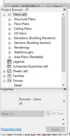
VIEW: It is nothing but the way we see an object in a different direction.
PLAN VIEW: The plan view is nothing but looking at an object from the top and this view helps us to draw or plan the rooms inside a building.
SECTIONAL VIEW: It is the view we get when a building (or) an object is cut along a line and viewed from one of the sides. this helps us to understand how it looks when it is cut from there.
ELEVATION VIEW: It is the view obtained when we look at something from the side, it shows how tall the object is and how it looks from the sides.
In the property browser of Revit software, we have all these views, using which we can clearly design and document a project properly and clearly.
9)
AIM: TO create a sheet template and create multiple sheets as mentioned.
TOOLS USED:
View
Sheet
Properties
Graphics
Insert
Image
PROCEDURE:
- In the view menu click on the sheet tool and select A1 METRIC sheet and click ok.
- Name the sheets as required and go the to insert option and lick on the image option and insert the image onto the sheet.
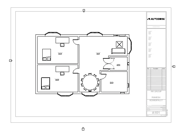
A 101 GROUND FLOOR ARCHITECTURE PLAN.
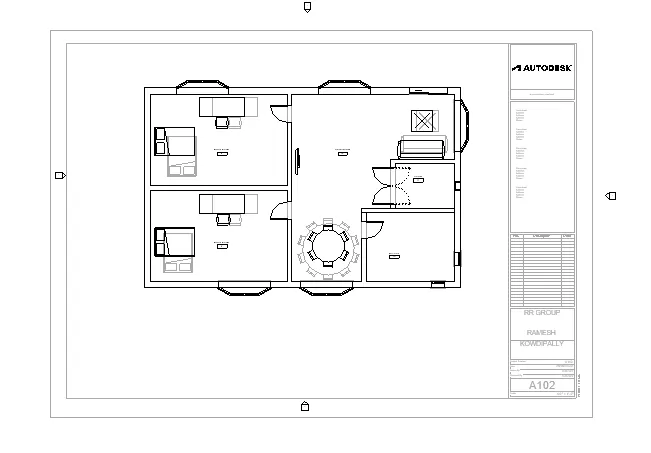
A FIRST-FLOOR FLOOR ARCHITECTURE PLAN.
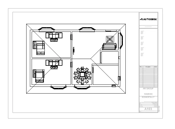
A 103 ROOF PLAN.
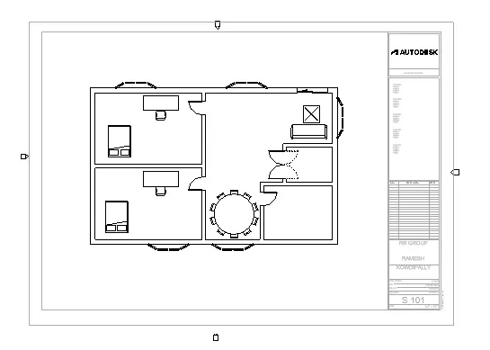
S 101 GROUND FLOOR STRUCTURAL PLAN.
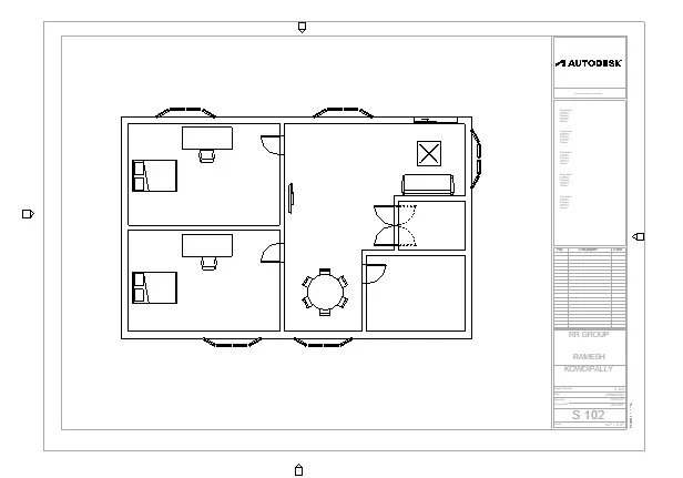
S102 FIRST FLOOR STRUCTURAL PLAN.
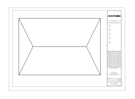
S 103 ROOF FRAMING PLAN.
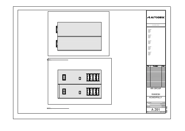
A 201 NORTH-SOUTH ELEVATION.
A 202 EAST-WEST ELEVATIONS.
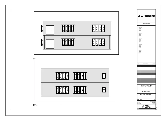
RESULT: The required sheet templates are obtained.
10)
AIM: To create camera views and create sheets naming A 501,502 ETC.
TOOLS USED:
View tab
3D view
Camera
PROCEDURE:
- In the 3d view of view tab, click on the camera view and set it as required t see the camera view.
- In the same way as we did above create new sheets and paste the camera views into the sheets.
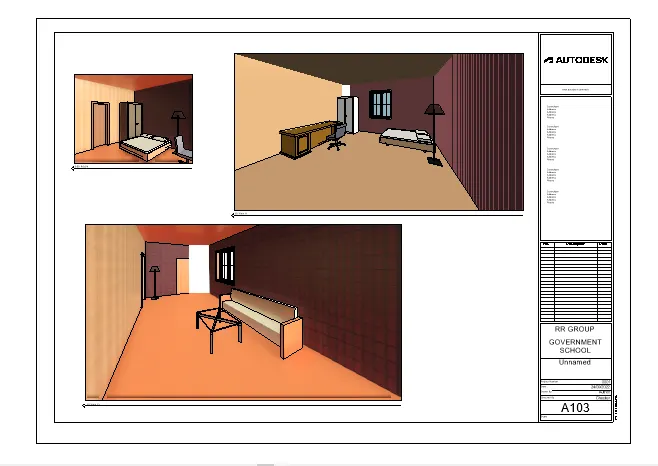
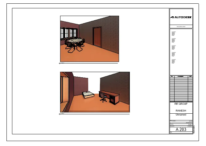
RESULT: A 501,502,AND etc,