3D Creation of Celing, Roof, Architectural plan, Structural plan, Sectional view, Elevation view and Camera specific view for a house plan using REVIT
AIM:
To proceed from the first floor level. Modl a ceiling from the architecture tab above the walls at the first floor level
INTRODUCTION:
In the Revit Architectural template we are provided with a CEILING option which we can create through two approaches
1.AUTOMATICALLY
2. SKETCH METHOD
Just like Floors and Roofs, Revit Ceilings consist of 3D model geometry and non-graphical parametric data. They are created by use of the dedicated Ceiling tool. There are 2 methods of creating Ceilings- each with their own pros and cons, which I will explain at the end of the tutorial. To make this tutorial a little more realistic, I have created a simple building to which we can add some Ceiling elements.
-
Automatic Ceiling: This will make Revit detect where there are bounding Walls that enclose potential ceiling spaces. In short- Revit is going to try and guess from your model where ceilings should be created.
-
Sketch Ceiling: This allows you to sketch (albeit precisely) where you want your Ceiling elements created. This is a similar process to the one we used in the Floors tutorial.
In this challange I have used the “Sketch Ceiling” option, Revit immediately enters Sketch Mode. Before we proceed, make sure that the options on the Ribbon are set to (1) “Boundary Line” and (2) “Find Walls”. We can of course manually draw the Boundary Lines where we would like the perimeter of the Ceiling to be. But by using the “Find Walls” tools, Revit will allow us to quickly find the walls we are interested in and create Boundary Lines along them.
So now I can just hove over the Walls in my model (still using a Reflected Ceiling Plan View). With each click of the mouse, Revit places a Ceiling Boundary Line along the length of the corresponding wall
PROCEDURE:
Open a new sheet and set units as feet and inches
Taken the ceiling area by selecting use of project browser
In above the toolbar, click the ceiling option and make the drawing
Set into the floor plan using ceiling on project browser
Use the sketch option to draw the ceiling
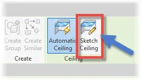
Now just hove over the Walls in my model (still using a Reflected Ceiling Plan View). With each click of the mouse, Revit places a Ceiling Boundary Line along the length of the corresponding wall
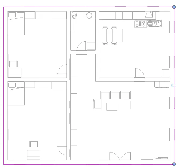
After drawing the ceiling give the offset height of ceiling
Finally click OK and check in the 3D option
RESULT
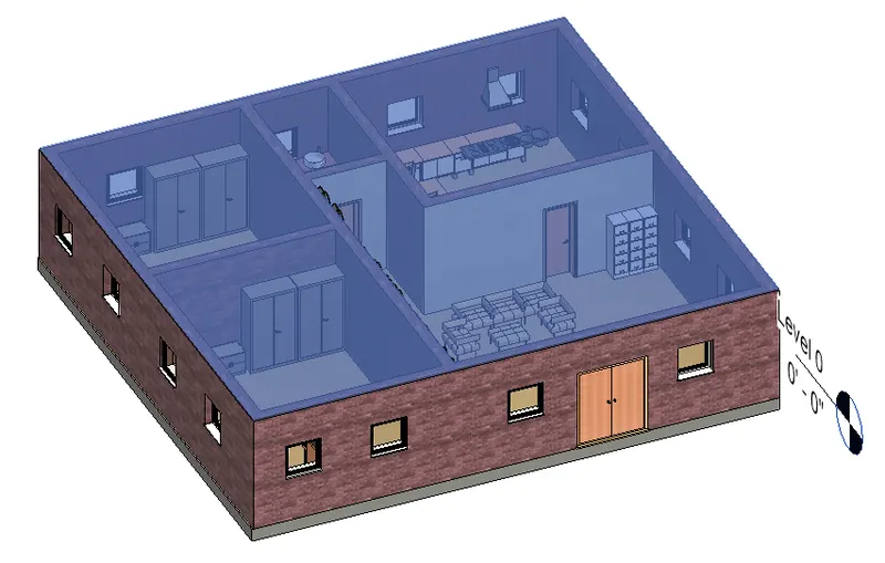
2) Model a roof above the ceiling by selecting the footprints of the ceiling. Using the adjustment toolbars appearing on-screen adjust the roof slope to 10 degrees
AIM:
To model a roof above the ceiling by selecting the footprints of the ceiling. Using the adjustment toolbars appearing on-screen adjust the roof slope to 10 degrees
INTRODUCTION:
Revit offers several methods of creating roofs. Choose the method that meets the best for our requirements.
Roof by Footprint
With the roof by footprint method, you specify a 2D sketch of the perimeter of the roof in plan view. You then define the slopes of the roof by identifying the lines in the footprint that are edges of sloping roof planes. The sketch of the footprint must be a closed loop that represents the exterior of the roof. The sketch can alsocontain other closed loops inside the perimeter that define openings in the roof. The plan level at which you sketch determines the level of the roof.
Roof by Extrusion
With the Roof by Extrusion method, you sketch the profile of the top of the roof in an elevation or section view, and then extrude the roof. You set the start and end point of the roof to determine the depth of the extrusion. You can use a combination of straight lines and arcs to create the profile. The location of the profile in the elevation view determines the height of the roof. The sketch should be a series of connected lines or arcs that are not closed in a loop. Revit applies the roof structure according to the type of roof.
Roof from Mass Instances
The Roof by Face tool lets you create roofs on any non-vertical faces of a mass.
PROCEDURE:
The process is same as that of the ceiling option
Open a new sheet ans set units
In the toolbar taken a roof option
We have to select the footprint in roof option
Pick the sketch boundary line option
Sketch the boundary line
Click OK
In the properties browser given the slope value as 10 degree
Click OK
Finally check the roof in 3d view
RESULT
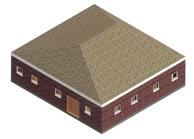
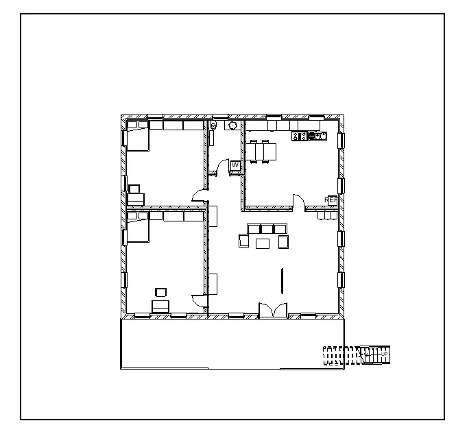
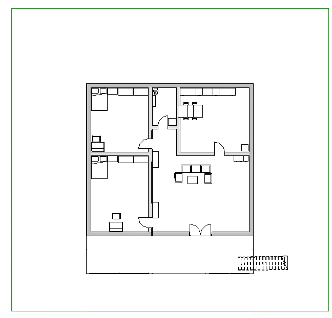
3) Using the file saved from weeks 2 to 4, create plan views for ground floor level and first-floor level including all the walls, floors, and components. Separate them to architecture and structural plans
a. Architecture plan must have walls, floors, and all the components placed within the building
b. Structure plan must have details of only walls, floors, and columns
AIM:
By using the file saved from weeks 2 to 4, create plan views for ground floor level and first-floor level including all the walls, floors, and components. Separate them to architecture and structural plans
INTRODUCTION:
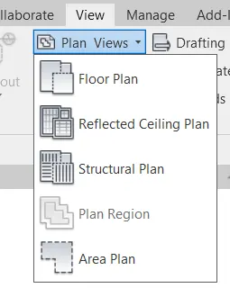
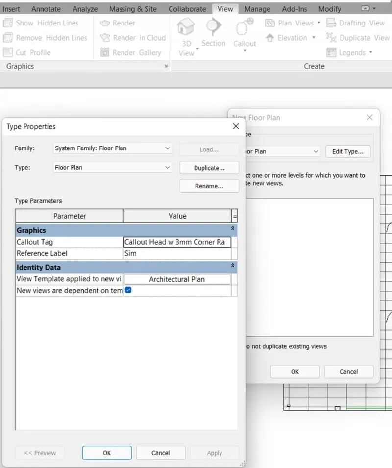
The floor plan view is the default view in a new architectural project. Most projects include at least one floor plan. Floor plan views are created automatically as you add new levels to your project. In a 2D view, display a floor plan, a reflected ceiling plan, or structural plan.
The structural plan view is the default view when you start a new project using a structural template. Most projects include at least one structural plan. New structural plan views are created automatically as you add new levels to your project. You can create multiple structural plan view types.
Engineers view plans at different orientations in different countries. Revit provides for this variation with the View Direction type parameter for structural plans.
4) Using annotate toolbar add dimensions to all the walls and floors with reference to the longitudinal and transverse grids created in the project file
a. The architecture plan dimensions include details on where the components are placed within the buildings with relation to grids. Overall dimensions are sufficient for architecture plans
b. The Structure plan dimensions must include details on the position of all the walls and interior walls with reference to grids. Locate all the framing components of the building with reference to a fixed point using Structural plans
AIM:
To use the annotate toolbar add dimensions to all the walls and floors with reference to the longitudinal and transverse grids created in the project file
INTRODUCTION:
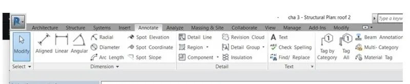
Annotation options in revit
| DI | ALIGNED DIMENSION / Creates an aligned dimension. |
| DL | DETAIL LINE / Creates view-specific lines. |
| EL | SPOT ELEVATION / Displays the elevation of a selected point. |
| FR | FIND/REPLACE / Find and replace. |
| GP | MODEL GROUP:CREATE GROUP; DETAIL GROUP:CREATE GROUP / Creates a group of elements. |
| RT | TAG ROOM; ROOM TAG / Tags the selected room. |
| TG | TAG BY CATEGORY / Applies tags to elements based on their categories. |
| TX | TEXT / Adds text. |
Grids in revit
Grids are annotation elements that help organize your design.
On the ribbon, click Grid
- Architecture tab>Datum panel>Grid
- Structure tab>Datum panel>Grid
- Click Modify | Place Grid tab>Draw panel and select a sketch option.
Use Pick Lines to snap the grid to an existing line, such as a wall.
Click when the grid is the correct length.Revit automatically numbers each grid. To change the grid number, click the number, enter the new value, and press ENTER. You can use letters for grid line values. If you change the first grid number to a letter, all subsequent grid lines update appropriately.
As you draw grid lines, the heads and tails of the lines can align to one another. If grid lines are aligned and you select a line, a lock appears to indicate the alignment. If you move the grid extents, all aligned grid lines move with it.
PROCEDURE:
Open the new sheet and set the unit
Set the levels in elevation view
In the above tool bar pick the modify option
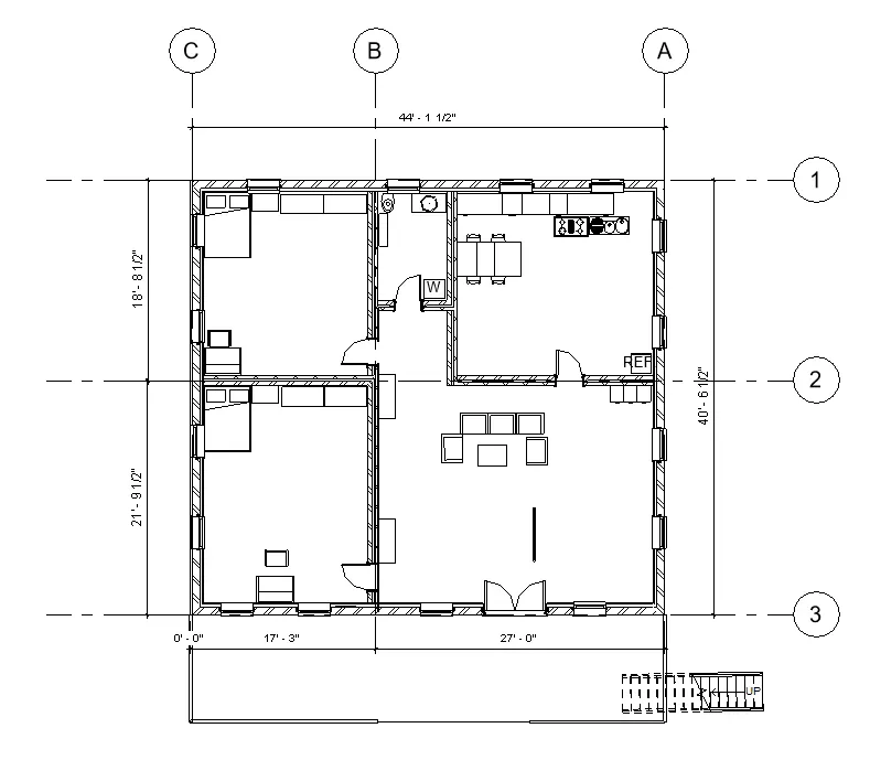
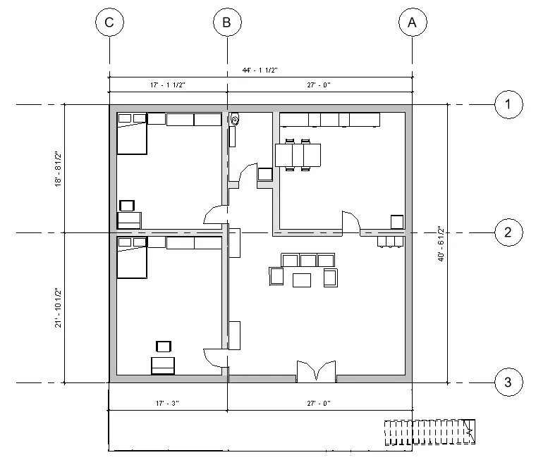
It provides the essential details to build a design.
Construction documents are the records that you share with clients, engineers, and construction professionals to communicate a design. For example, clients need to see floor plans, elevations, and 3D drawings of the design for approval. Engineers from other disciplines will want to see those drawings, as well as more detailed drawings, to help them understand the building model and how it affects their work. Construction professionals need all of these drawings, as well as schedules and material takeoffs, to build the design.
A construction document set (also called a drawing set or a sheet set) consists of several sheets. Each sheet contains one or more drawings and schedules for the building design.
- Open the Revit project.
- Click View tab>Sheet Composition panel>Sheet
- In the New Sheet dialog, select a title block from the list. If the list does not show the desired title block, click Load. In the Library folder, open the Titleblocks folder, or navigate to the folder where the title block resides. Select the title block to load, and click Open.Select None to create a Sheet without a title block.
- Click OK.Select a title block, as follows
- For information about title blocks, see Title Blocks.
- Enter information in the title block of the sheet.See Specifying Title Block Information for Sheets.
- Add views to the sheet.See Adding Views to a Sheet.
- Change the default number and name that Revit Architecture assigned to the sheet.
- See Renaming a Sheet. The sheet number and name display in the Project Browser under Sheets all
PROCEDURE:
Open the new sheet and set the unit
Set the levels
Select the sheet option in the above toolbar
Edit the sheet size as what you want like (A0,A1,A2,A3,A4)
Pick a sheet say A1
And pick the floor plan and drag into the sheet
And edit the size of the picture use the scale option in properties box
RESULT
VIEWS HAVE BEEN DISPLAYED ON THE SHEETS SUCESSSFULLY
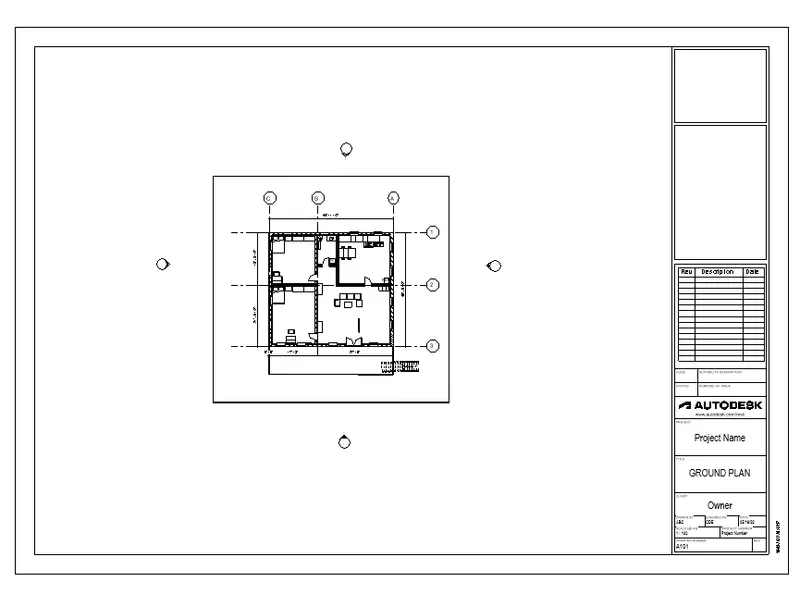
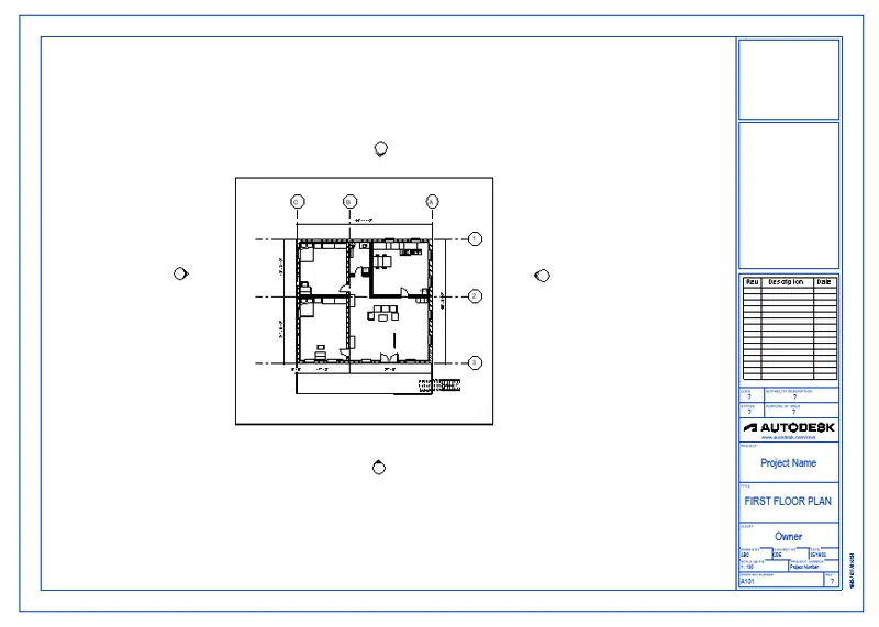
6) Using the elevation tab create the elevation views, looking at your building from East, North, South, and West
AIM:
Use the elevation tab create the elevation views, looking at your building from East, North, South, and West
INTRODUCTION:
An “elevation” is a drawing that shows the front or side of something. A floor plan, by contrast, shows a space from above – as if you are looking down on the room from the ceiling. Thus, you see the tops of everything, but you cannot view the front, side or back of an object. An elevation gives you the chance to see everything from the other viewpoints.
When we create a project with default template 4 elevation views are included : north, south, east west . Its in elevatio views where you sketch level lines.For each level line that we sketch, a corresponding plan view is created
PROCEDURE:
Open the new sheet and set the unit
Set the levels
After finishing the diagram in 3d model
Pick the elevation i above the tool bar
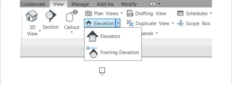
After taken the elevation option and place into the scree
It depends upon the diagram
We can place the elevations in four sides_ North, South, West , East
Check the elevation in project browser
RESULT
ELEVATIONS HAVE BEEN CREATED SUCESSFULLY
EAST ELEVATION

NORTH ELEVATION
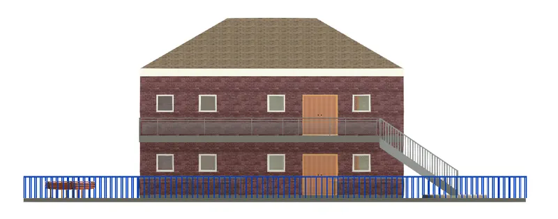
EAST ELEVATION
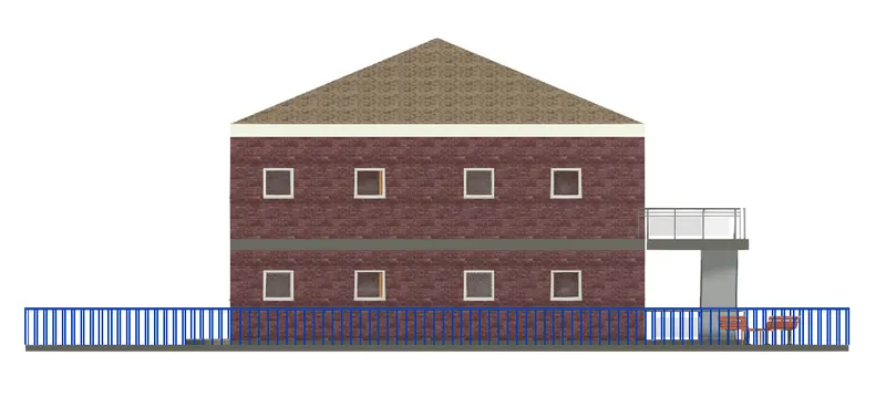
SOUTH ELEVATION
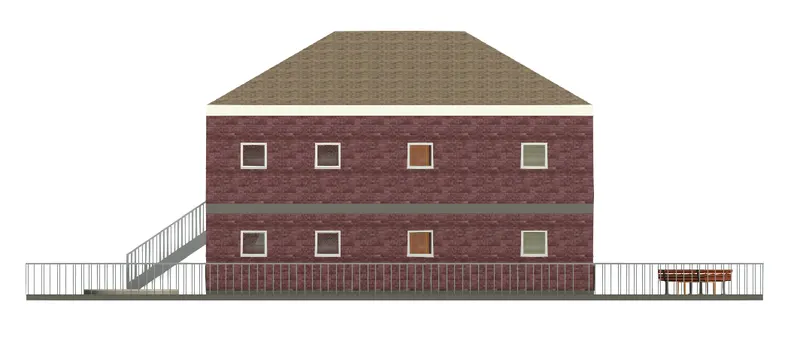
7) Produce section cut through each room either cutting across longitudinally or in a transverse direction
AIM:
To produce section cut through each room either cutting across longitudinally or in a transverse direction
INTRODUCTION:
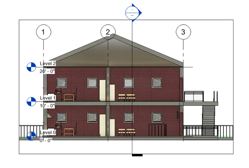
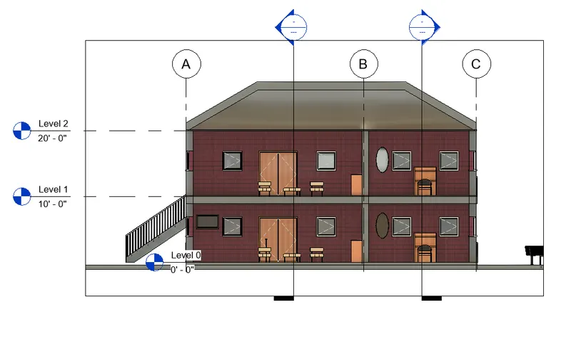
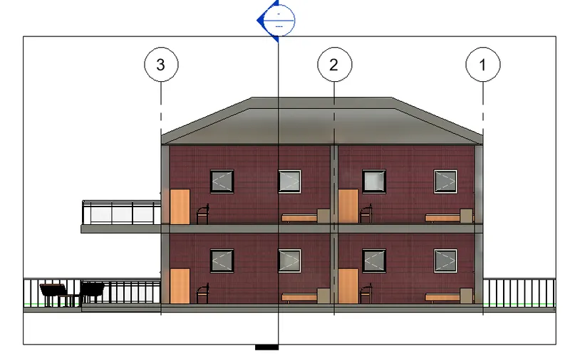
A sectional view or a section looks inside an object. Sections are used to clarify the interior construction of a part that can not be clearly described by hidden lines in exterior views. By taking an imaginary cut through the object and removing a portion, the inside features may be seen more clearly. The cut line is called a “cutting plane”, and can be done in several ways.The following slides will help show the several methods or types of “section views”
It is very important to Visualize what the part will look like after it is cut open. Choosing the type of section and location of the cutting plane. Making the cut and drawing the view in the proper location.
PROCEDURE:
Open the new sheet and set the units
Set the levels
aken the section options in above the tool bar
And section option is make cut the elevation and view the cutting elevation on the screen
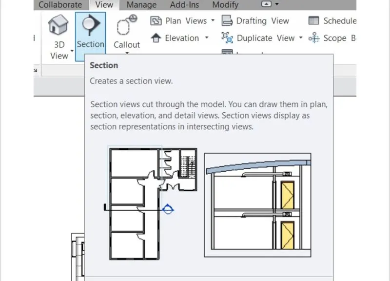
Create the section view with use of section option
And cut the plan view with use of section
And saw the section in the section view on project browser
Check on the 3d view with use of section in project browser
RESULT
SECTIONAL VIEWS HAVE BEEN CREATED SUCESSFULLY
8) Classify the views, Plan Views, Section Views, and Elevation views to either Design or Documentation category using Properties browser
AIM:
To classify the views, Plan Views, Section Views, and Elevation views to either Design or Documentation category using Properties browser
INTRODUCTION:
A structural drawing, a type of engineering drawing, is a plan or set of plans and details for how a building or other structure will be built. Structural drawings are generally prepared by registered professional engineers, and based on information provided by architectural drawings. The structural drawings are primarily concerned with the load-carrying members of a structure. They outline the size and types of materials to be used, as well as the general demands for connections. They do not address architectural details like surface finishes, partition walls, or mechanical systems. The structural drawings communicate the design of the building's structure to the building authority for review. Structural drawings are also included with a proposed building's contract documents, which guide contractors in detailing, fabricating, and installing parts of the structure.
The structural plan drawings show the foundation, floor, and roof plan of the building. These plans provide information like size and location of the structural elements present in the respective plans.
Elevations show the exterior walls of a building or structure. In elevation drawings you can find the height of building (floors and roof elevations) and structural properties of elements present in the walls and that cannot be seen in plan drawings.
Sections plans are referenced in the plan view drawings and provide information about elements that cannot be see in plan drawings. The sections usually are cut through walls or structural elements that are not typical and the constructor needs to be aware off.
The details drawings provide particular information on how to construct or connect the structural elements. The details can be reference in plans, elevations and sections.
PROCEDURE:
Open the new sheet and set the unit
Set the levels
Use the sheet option in views on toolbar
Set new sheet and modify the size
Taken the ground floor and drag into the sheet and modify the size with use of scale
Taken the first floor and drag into the sheet and modify the size with use of scale
Taken the section plan and drag into the sheet and modify the size with use of scale
Taken the section plan and drag into the sheet and modify the size with use of scale
Taken the elevation and drag into the sheet and modify the size with uses of scale
RESULT:
The views are created into the sheet as shown in the picture below
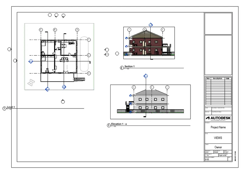
9) Using the sheet template produced create multiple sheets as follows
a. A 101- Ground Floor Architecture Plan
b. A 102- First Floor Architecture Plan
c. A 103- Roof Plan
d. S 101- Ground Floor Structural Plan
e. S 102- First Floor Structural Plan
f. S 103- Roof Framing Plan
g. A-201- North-South Elevations
h. A-202- East-West Elevations
Add additional sheets based on the sections created in your Revit file
AIM:
To use the sheet template produced create multiple sheets
INTRODUCTION:
In Revit Architecture, you create a sheet view for each sheet in a construction document set. You can then place multiple drawings or schedules on each sheet.
A sheet (also called a drawing sheet) is an individual page of a construction document set. In Revit Architecture, you create a sheet view for each sheet in the construction document set. You can then place multiple drawings or schedules on each sheet view.
ou can add one or more views of a building to a sheet, including floor plans, site plans, ceiling plans, elevations, 3D views, sections, detail views, drafting views, and rendered views. Each view can be placed on one sheet only. To add a particular view to multiple sheets in a project, create duplicate views, and place each one on a different sheet.
- Open the Revit project.
- Click View tab>Sheet Composition panel>Sheet
- In the New Sheet dialog, select a title block from the list. If the list does not show the desired title block, click Load. In the Library folder, open the Titleblocks folder, or navigate to the folder where the title block resides. Select the title block to load, and click Open.Select None to create a Sheet without a title block.
- Click OK.Select a title block, as follows
- For information about title blocks, see Title Blocks.
- Enter information in the title block of the sheet.See Specifying Title Block Information for Sheets.
- Add views to the sheet.See Adding Views to a Sheet.
- Change the default number and name that Revit Architecture assigned to the sheet.
- See Renaming a Sheet. The sheet number and name display in the Project Browser under Sheets all
TO ADD VIEWS TO SHEETS
- Open the sheet.
- To add a view to the sheet, use one of the following methods
- In the Project Browser, expand the list of views, locate the view, and drag it onto the sheet.
- Click View tab>Sheet Composition panel>Place View. In the Views dialog, select a view, and click Add View to Sheet.
- As you move the cursor over the sheet in the drawing area, a viewport for the selected view moves with it. Click to place the viewport in the desired location. Use the Guide Grid for precise placement on sheets.
- Repeat Steps 2 and 3 to add more views to the sheet, if desired.
- If needed, you can modify the individual views on the sheet as follows
- To change the view title that displays on the sheet, double-click the title, and edit it. See View Titles on Sheets.
- To move the view to a new location on the sheet, select its viewport, and drag it. You can align views to grid lines for precise placement. See Aligning Views on a Sheet.
When we make sheets, it represents as follows
PROCEDURE:
Open the new sheet and set the unit
Set the levels
Use the sheet option in views on toolbar
Set new sheet and modify the size
Here we can also set the name and number of the sheet individually
Here we want 8 sheets as per challange
In the project browser we see the sheet option and see the sheet option and create a sheet
First we take A-101- ground floor architectural plan and modify the size of the diagram .
As we move a drawing or schedule onto a sheet, a viewport displays. A viewport is a representation of the drawing or schedule when it is placed on a sheet
Second we take A-102- first floor architectural plan and modify the size of the diagram
As we move a drawing or schedule onto a sheet, a viewport displays. A viewport is a representation of the drawing or schedule when it is placed on a sheet
Thirdly we take A-103- roof plan and modify the size of the diagram
As we move a drawing or schedule onto a sheet, a viewport displays. A viewport is a representation of the drawing or schedule when it is placed on a sheet
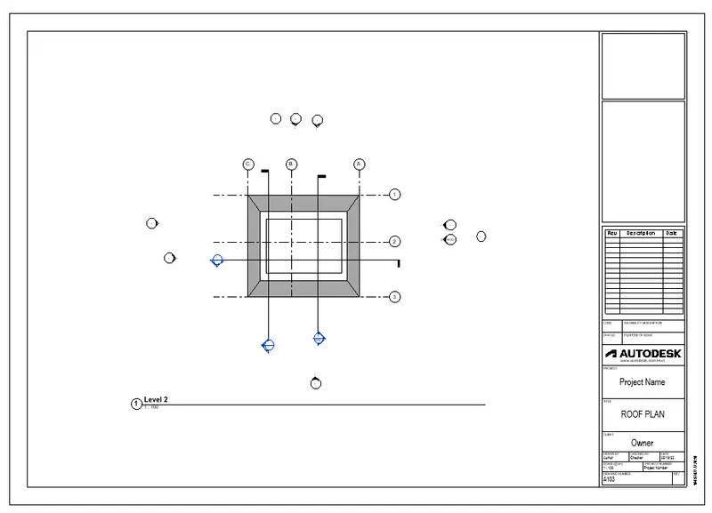
Fourthly we take S-101- ground floor structural plan and modify the size of the diagram
As we move a drawing or schedule onto a sheet, a viewport displays. A viewport is a representation of the drawing or schedule when it is placed on a sheet
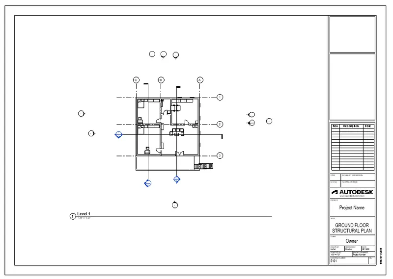
Fifthly we take S-102- first floor structural plan and modify the size of the diagram
As we move a drawing or schedule onto a sheet, a viewport displays. A viewport is a representation of the drawing or schedule when it is placed on a sheet
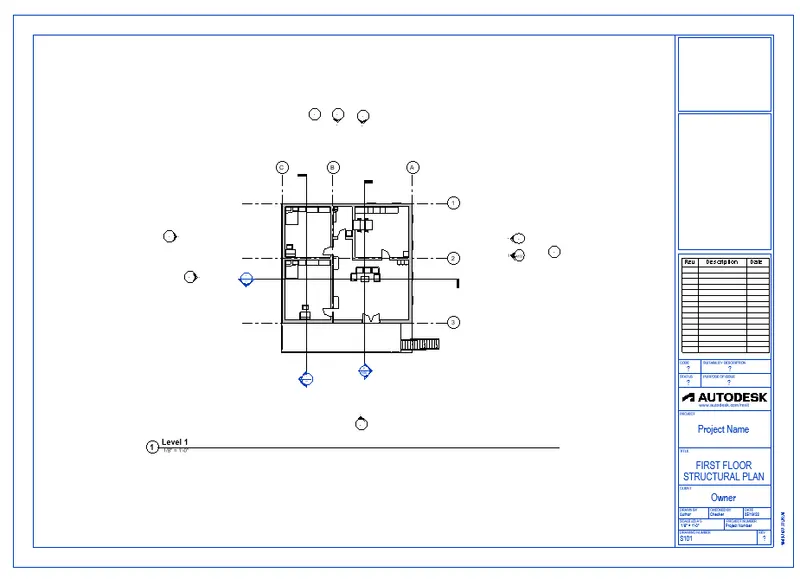
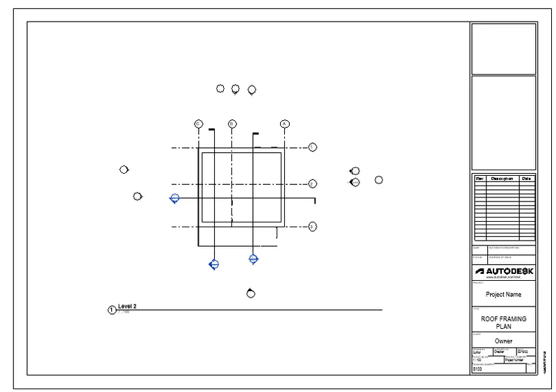
Sixthly we take S-103- roof framing plan and modify the size of the diagram
As we move a drawing or schedule onto a sheet, a viewport displays. A viewport is a representation of the drawing or schedule when it is placed on a sheet
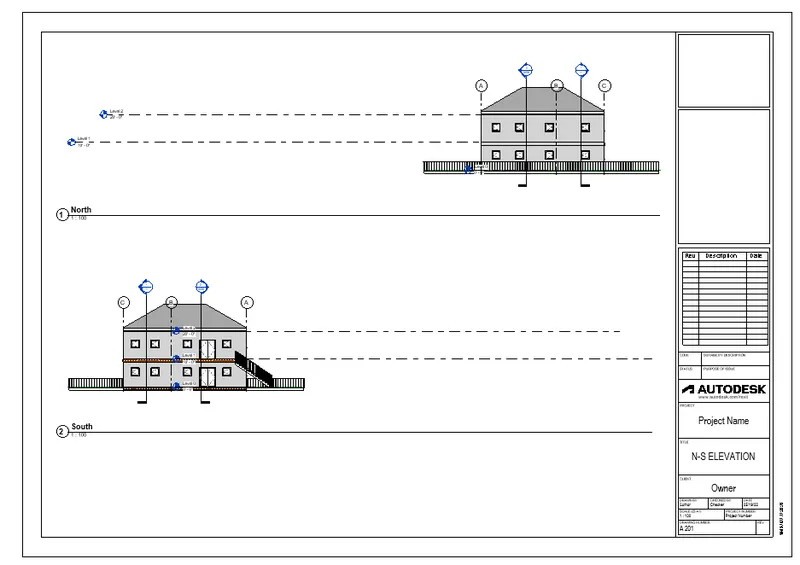
Seventhly we take A-201- NORTH SOUTH ELEVATION and modify the size of the diagram
As we move a drawing or schedule onto a sheet, a viewport displays. A viewport is a representation of the drawing or schedule when it is placed on a sheet
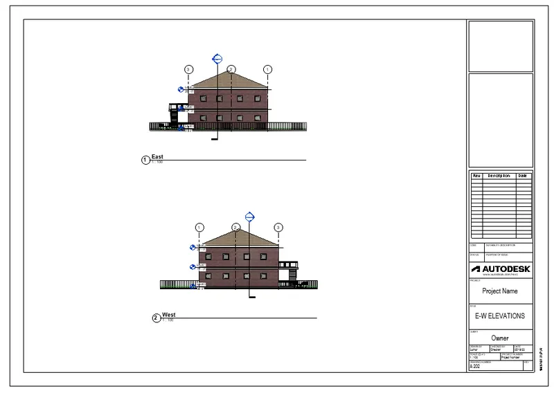
Eightly we take A-202- EAST WEST ELEVATION and modify the size of the diagram
As we move a drawing or schedule onto a sheet, a viewport displays. A viewport is a representation of the drawing or schedule when it is placed on a sheet
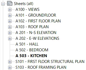
When we add sheets to a Revit project, they are listed in the Project Browser under Sheets (all).
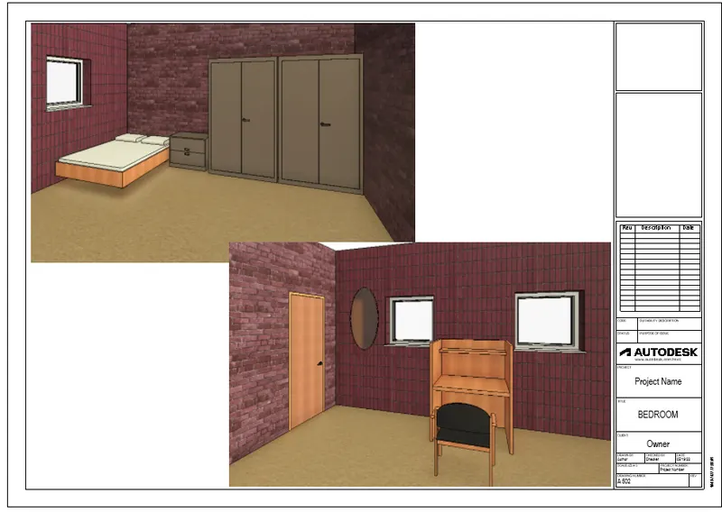
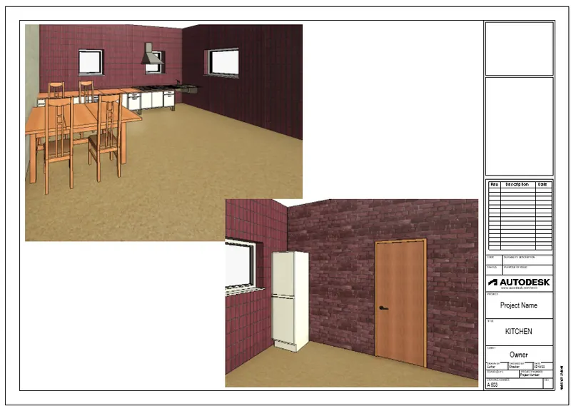
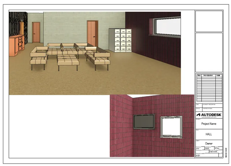
10) Create a camera-specific view or a 3D view in each room ( living, dining, bedroom). Based on the views create a new set of sheets starting A-501 (you can add as many sheets after, 502, 503.. n)to place the 3D view images. Produce the sheets as a part of project drafting.
AIM:
To Create a camera-specific view or a 3D view in each room ( living, dining, bedroom). Based on the views create a new set of sheets. Produce the sheets as a part of project drafting.
INTRODUCTION:
The Perspective option controls whether a 3D view displays as perspective instead of orthographic.
- Open a plan, section, or elevation view.
- Click View tab>Create panel>3D View drop-down>Camera.
Note: If you clear the Perspective option on the Options Bar, the view that is created is an orthographic 3D view and not a perspective view.
- Click in the drawing area to place the camera.
- Drag the cursor to the desired target and click to place it.
Revit creates a perspective 3D view and assigns a name to the view: 3D View1, 3D View2, and so on. To rename the view, in the Project Browser right-click it, and select Rename.