3D Creation of Celing, Roof, Architectural plan, Structural plan, Sectional view, Elevation view and Camera specific view for a house plan using REVIT
1. Based on the project saved from Week 3, proceed from the First Floor Level. Model a Ceiling from the architecture tab above the walls at the first-floor level
AIM:- To model a Ceiling from the architecture tab above the walls at the first-floor level.
INTRODUCTION:-
- Create a ceiling defined by walls, or sketch its boundary. Create ceilings in a reflected ceiling plan view.
- Ceilings are level-based elements: we can create them at a specified distance above the level in which they reside. For example, if we create a ceiling on Level 1, it may be placed 3 meters above Level 1. We specify this offset in the ceiling type properties.
- Two kinds of ceilings can be placed in our model, basic ceilings and compound ceilings.
- Basic ceilings are planar elements with no thickness. Surface material patterns can be applied to the basic ceiling plane.
- Compound ceilings are composed of layers with a material thickness defined to each layer.
- You can create sloped ceilings and cathedral ceilings in the building model.
- To create a sloped ceiling, use one of the following methods:
- Draw a slope arrow, while sketching or editing the ceiling boundary.
- Specify a value for the Offset from Base property for parallel ceiling sketch lines.
- Specify for the Defines Slope and Slope properties for a single ceiling sketch line.
PROCEDURE:-
- Use the Ceiling tool to create a ceiling in a reflected ceiling plan view.
- Open a ceiling plan view.
- Click Architecture tab, in Build panel, Ceiling.
- In the Type Selector, select a ceiling type.

- To Place a ceiling, Use walls as ceiling boundaries.
- By default, the Automatic Ceiling tool is active. When you click inside walls that form a closed loop, the tool places a ceiling within those boundaries. It ignores room separator lines.
- Sketch ceiling boundaries, Click Modify|Place Ceiling tab, Ceiling panel, Sketch Ceiling.
- Use tools in the Draw panel of the ribbon to sketch a closed loop that defines the ceiling boundary.
- Using Pick line option, create an opening in the ceiling, sketch another closed loop within its boundary.
- On the ribbon, click tick button to finish the edit mode.
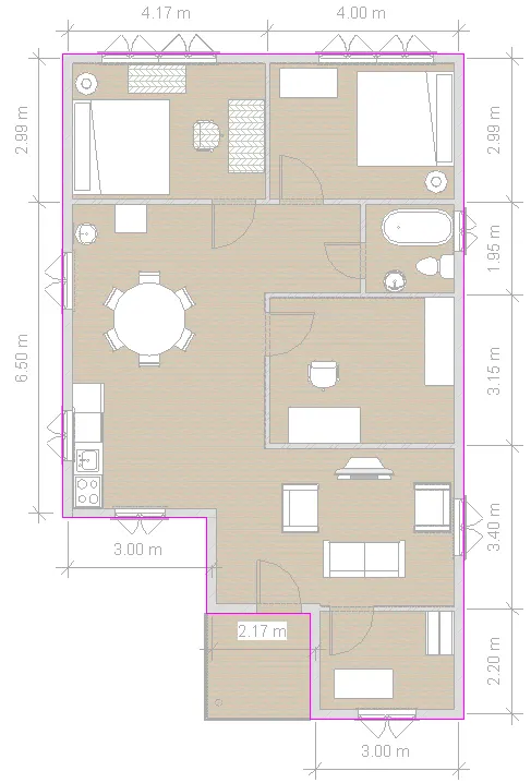
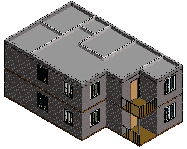
- Ceiling is created and change the view from plan view to 3d view to view the ceiling as shown in result.
RESULT:-
Ceiling is modeled from the architecture tab above the walls at the first-floor level.
_____________________________________________________________________________________________________
2. Model a roof above the ceiling by selecting the footprints of the ceiling. Using the adjustment toolbars appearing on-screen adjust the roof slope to 10 degrees
AIM:- To model a roof above the ceiling by selecting the footprints of the ceiling.
INTRODUCTION:-
- Roof, covering of the top of a building, serving to protect against rain, snow, sunlight, wind, and extremes of temperature. Roofs have been constructed in a wide variety of forms—flat, pitched, vaulted, domed, or in combinations—as dictated by technical, economic, or aesthetic considerations.
- Revit offers several methods of creating roofs. Choose the method that best meets the needs of our design. We can create a roof:-
- from a building footprint
- as an extrusion
- with sloped glazing
- from a mass instances ; A roof cannot cut through windows or doors.
ROOF BY FOOTPRINT:-
- 2D closed-loop sketch of the roof perimeter
- Created when we select walls or draw lines in plan view
- Created at level of view in which it was sketched
- Height is controlled by Base Height Offset property
- Openings are defined by additional closed loops
- Slopes are defined when you apply a slope parameter to sketch lines.
ROOF BY EXTRUSION:-
- Open-loop sketch of the roof profile
- Created when we use lines and arcs to sketch the profile in an elevation view
- Height is controlled by the location of the sketch in elevation view
- Depth is calculated by Revit based on size of sketch, unless you specify start and end points.
- It is helpful to use reference planes when sketching the profile of an extruded roof. For example, sketch 3 vertical reference planes parallel to one another, and then sketch a horizontal reference plane that intersects all 3 vertical planes.
- The Roof by Extrusion tool lets you create a roof with simple slopes.
- To create a roof with complex slopes, you can use massing.
- After we create a roof by extrusion, you can rehost the roof oredit the work plane of the roof.
SLOPED GLAZING:-
- We can create sloped glazing using the footprint or extrusion method. Sloped glazing has one or more slope-defining lines and can join to curtain walls and basic wall types.
PROCEDURE:-
- Creates a roof using the building footprint to define its boundaries.
- Display a floor plan view or a reflected ceiling plan view.
- Click Architecture tab - Build panel - Roof drop-down - (Roof by Footprint).
-
Note: If you try to add a roof on the lowest level, a dialog prompts you to move it to a higher level. If you choose not to move the roof to a different level, Revit notifies you later if the roof is too low.
- On the Draw panel, select a sketch or pick tool. To edit roof properties before sketching, use the Properties palette.
Note: When using Pick Walls, you can specify the overhang before you sketch the roof. On the Options Bar, select Extend to wall core if you want the overhang to be measured from the core of the wall, and then specify a value for Overhang.
- Sketch, or pick, a closed loop for the roof.
- Specify slope defining lines. To change the slope definition of a line, select the line and, on the Properties palette, click Defines Roof Slope. You can then change the slope value. When a roof line is set to slope defining, this symbol appears adjacent to it.
- Click on tick button to (Finish Edit Mode).
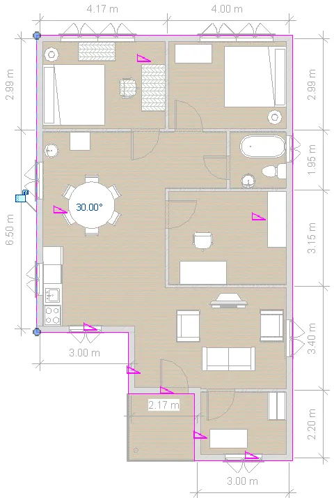
- Now, open a 3D view
- From the figure attached is clear that roof isn't attached. Go to property platte change the top offset to -0.15m..
- Thereby the roof is attched to walls.
- On the Properties palette, select or clear Defines Roof Slope.
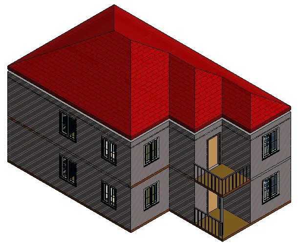
- To specify roof pitch, select a slope-defining boundary line, click the numeric slope definition in the drawing area, and enter a value for the slope as 10 degree.
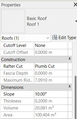
- The changed slope degree is shown in result.
RESULT:-
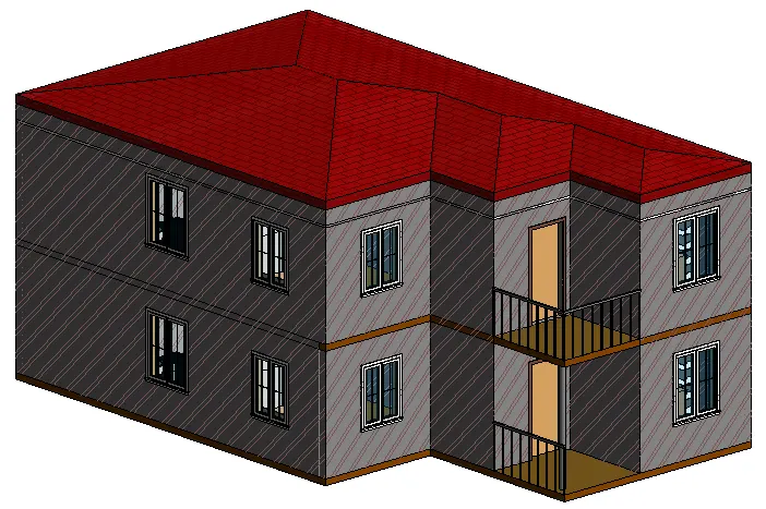
The roof has been created and the slope is aadjusted to 10 degree as shown.
_____________________________________________________________________________________________________
3. Using the file saved from weeks 2 to 4, create plan views for ground floor level and first-floor level including all the walls, floors, and components. Separate them to
architecture and structural plans
a. Architecture plan must have walls, floors, and all the components placed within the building
b. Structure plan must have details of only walls, floors, and columns
AIM:-
To create plan views for ground floor level and first-floor level including all the walls, floors, and components and then Separate them to architecture and structural plans.
INTRODUCTION:-
- Structural plans primarily concerned with load carrying members of a structure such as beams, columns, walls, stairs etc.
- Architectural plans consists of architectural components such as furniture, architectural components, doors, windows etc.
- In Revit software, the structural plans are created automatically if we model the architectural plan using the structural plan view of the plan view tool of the view tab.
PROCEDURE:-
- Open the Revit software, select the residential unit file and open it from Revit home page.
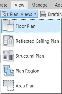
- To create the architectural plan view, go to the view tab, click on the drop down of plan view, select the floor plan option from the list.
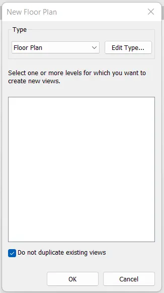
- After selecting floor plan view it will open the new floor plan dialog box, select the edit type from it.
- After clicking edit type it will open the type properties dialog box, from this dialog box make sure view template applied to new view is architectural template and select ok it will again open the new plan view dialog box.
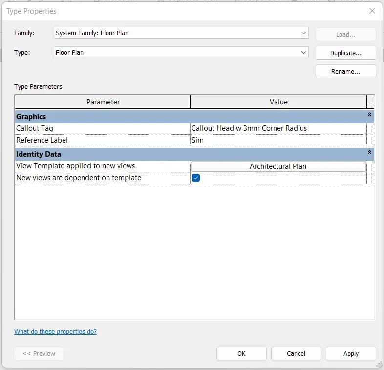
- Again, from new floor plan remove the tick mark to create the duplicate view, select the ground floor plan and select ok.
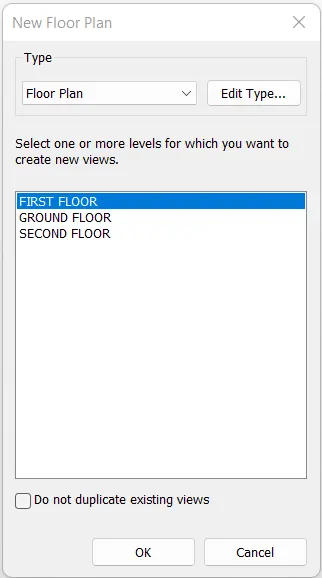
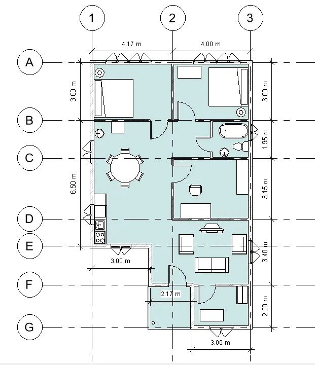
- The architectural plan view is shown below.
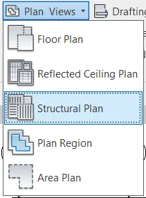
- To create the structural plan of the ground floor, again go to view tab, click on the plan view drop down, select the structural plan from the list, it will open the new structural plan dialog box.
- Select the edit type option from new structural plan dialog box, make sure view template to applied view is structural framing plan and select ok.
- After clicking edit type it will open the type properties dialog box, from this dialog box make sure view template applied to new view is structural template and select ok it will again open the new plan view dialog box.
- After selecting ok it will open again the new structural view dialog box, select the ground floor level and select ok.
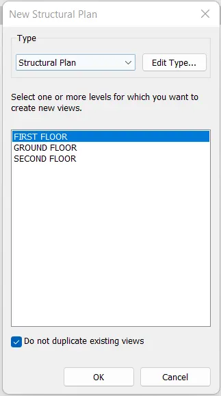
- After clicking edit type it will open the type properties dialog box, from this dialog box make sure view template applied to new view is architectural template and select ok it will again open the new plan view dialog box.
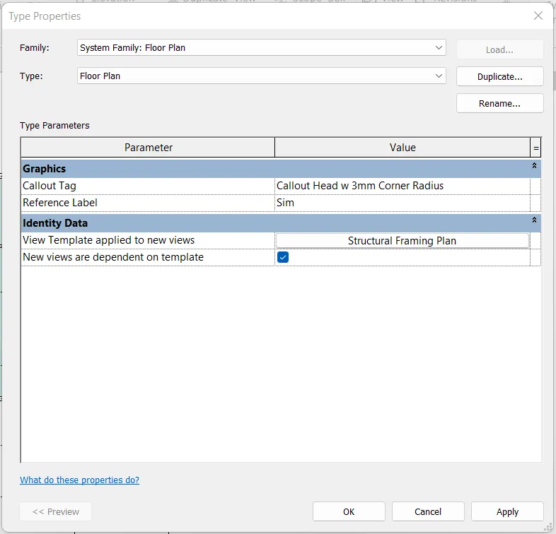
- The ground floor structural plan view.
- The ground floor structural plan is shown below.
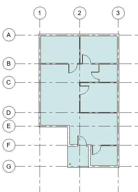
- Similarly create the architectural and structural plan views for first floor plan as shown below and save the file using top toolbar using save icon.
RESULT:-
The plan views for ground floor level and first-floor level including all the walls, floors, and components and then Separated them to architecture and structural plans as shown.
- Ground floor Architectural floor plan view:-
- Ground floor Structural plan view:-
_____________________________________________________________________________________________________
4. Using annotate toolbar add dimensions to all the walls and floors with reference to the longitudinal and transverse grids created in the project file
a. The architecture plan dimensions include details on where the components are placed within the buildings with relation to grids. Overall dimensions are sufficient for architecture plans
b. The Structure plan dimensions must include details on the position of all the walls and interior walls with reference to grids. Locate all the framing components of the building with reference to a fixed point using Structural plans
AIM:-
To add dimensions to all walls and floors with reference to the longitudinal and transverse grids created in the project.
INTRODUCTION:-
- Dimensions are added into the architectural and structural plan views using the linear or aligned tool of dimension panel of the annotate tab.
- Dimensions add the details to the plans views which are helpful to locate the components with reference to the grid lines.
- Dimensions show measurements in a project.
- You can use arc end points as references when placing linear dimensions.
- Horizontal and vertical dimensions are available in the project environment only. You cannot create them in the Family Editor.
- Annotate tab - Dimension panel
- There are 2 types of dimensions:
- Temporary dimensions
- Permanent dimensions
- Temporary dimensions are the measurements that display in the drawing as you place elements or sketch lines, or when you select an element. These dimensions disappear when you complete the action or deselect the element.
- Permanent dimensions are measurements that you add to drawings to document the design. They are view-specific, and they print on sheets.
PROCEDURE:-
- Open the Revit software, select the last saved residential unit file from home page of Revit software and open it from home page of Revit.
- Double click on the first floor plan from property browser to open the architectural first floor plan.
- Go to the annotate tab, select the linear tool from dimension panel.

- Linear dimensions are placed between selected points. The dimensions are aligned to the horizontal or vertical axis of the view.
- The selected points are endpoints of elements or the intersection of references (for example, the join of 2 walls).
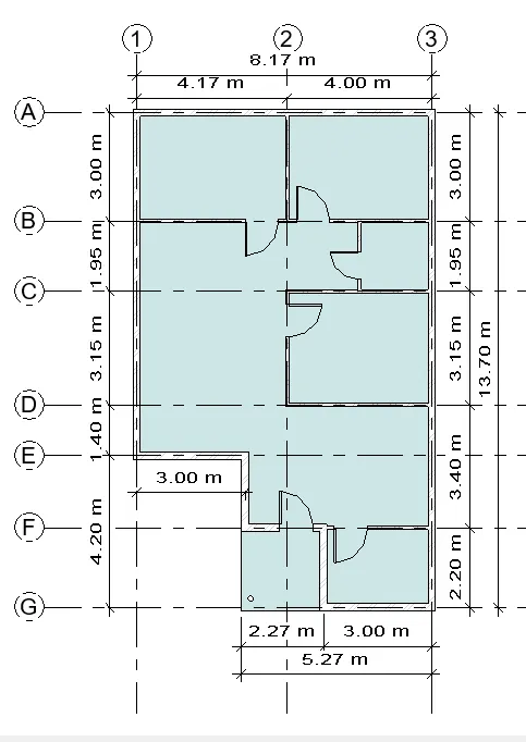
- Select the first corner point of wall, the select the second corner point of the wall, the move the cursor upward and place dimension line to appropriate position as shown below.
- Similarly give the dimensions to all other walls and floor wherever required as shown below.
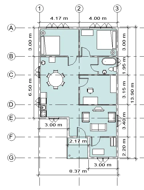
- Double click on the first floor structural plan from property browser to open the structural plan view.
- Again, go to annotate tab, select the linear option, select first point, select opposite corner point, move cursor in upward direction and place the dimension line at the appropriate position as shown below.
- Similarly, give dimensions to other components using the similar procedure as shown below and save the file using the save icon from top toolbar of Revit window.
RESULT:-
Therefore, dimensions are added to all the walls and floors with reference to the longitudinal and transverse grids in the Revit software by following above mentioned procedure as shown below.
- Ground floor Architectural floor plan view:-
- Ground floor Structural plan view:-
_____________________________________________________________________________________________________
5. Create a sheet template from the view tab and adjust the parameters on the sheet to add appropriate views
AIM:- To create the sheet template from view tab and adjust the parameters on the sheet to add appropriate views.
INTRODUCTION:-
- Create views on a project template before you start building the model to streamline the project documentation process.
- When creating a project template, you can include sheets in the template. Start with a blank project file, and create the standard views and levels that each project should include. Leave the views empty, but assign standard names to them. To create a standard set of construction documents, create sheets using the desired title blocks. Add views to the sheets, using the desired viewport templates and view title types. Then save the empty project as a project template.
- When you create a project using this project template, all of the views and sheets are already created and listed in the Project Browser. As you start to draw the building model in the project views, the views on the sheets update automatically. This technique streamlines the project documentation process and maintains organizational standards.
PROCEDURE:-
- Open rivet software, select the residential unit file from Revit homepage to open it.
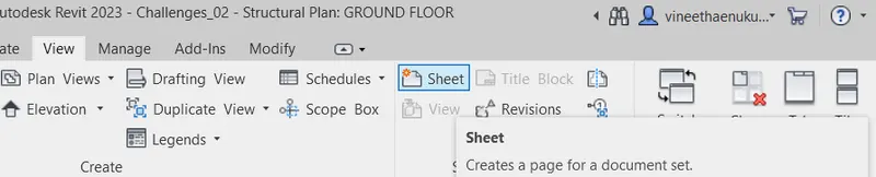
- For creating the sheet, go to view tab, select the sheet tool from sheet composition panel, it will open the new sheet dialog box.
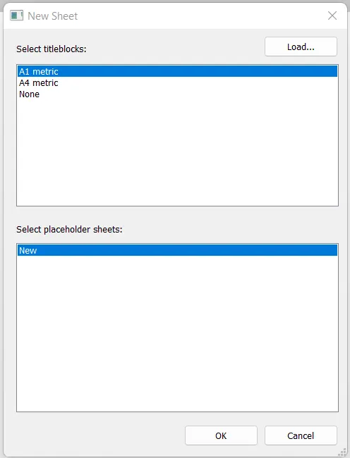
- Select the sheet paper size as A4 METRIC and select ok from dialog box, it will open the created sheet template as shown below.
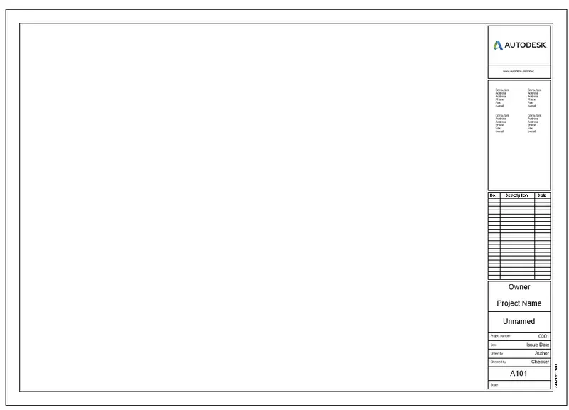
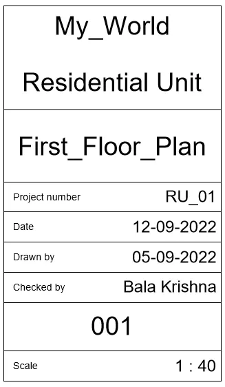
- To adjust the parameters on the sheet double click on the parameter and change it as per the required value as shown below or Go to toolbar - Mange - Project Information tab, click on it. Dialogue box appers on screen, there rename the text as per requirement and then click on apply and then click on ok.
- By that automatically the sheet information got changed.
- Similarly change all the parameters as per desired value as shown below.
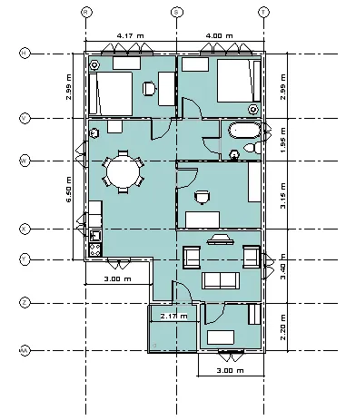
- For cropping the floor plan view, go to architectural ground floor plan by double clicking on ground floor plan view from the project browser.
- Select the show crop region tool from bottom tool bar of the Revit window and adjust the view as shown below.
- Again select hide the crop view region tool from bottom toolbar to hide the view region rectangle in the view.
- Go into template sheet view by double clicking on the sheet from project browser.
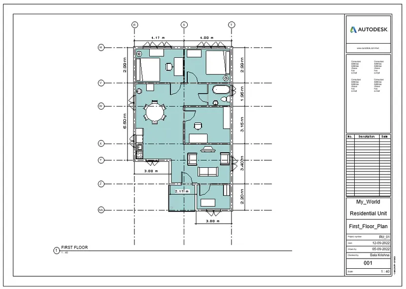
- Now, drag the architectural ground floor plan into sheet with the help of mouse and adjust it in appropriate position.
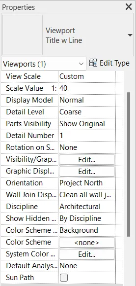
- Change the scale of the sheet from property window to the scale which properly fits into template sheet as shown below.
- Adjust the view at appropriate position as shown below
RESULT:-
The sheet template from view tab and adjusted the parameters on the sheet to add appropriate views.
_____________________________________________________________________________________________________
6. Using the elevation tab create the elevation views, looking at your building from East, North, South, and West
AIM:- To create the East, North, South and West elevation views of the building using the elevation tab.
INTRODUCTION:-
- Building elevation means the entire side of a building, from ground level to the roofline, as viewed perpendicular to the walls on that side of the building.
- Elevation views are created in the Revit software by using the elevation tool of view tab of create panel.
- Elevation views include south, north, east and west view.
PROCEDURE:-
- Open the Revit software, select the residential unit file from home page of Revit and open it.
- Double click on the ground floor plan from project browser and open the view.
- Go to the view tab, select the drop down of elevation tool from create panel, select the elevation option from list and place the elevation at desired location at the top of the plan.
- Place the cursor near a wall, and click to place the elevation symbol. The plan view shown below is included with stairs. Where stairs and railing is sketched out from tool bar.
- 3D view shaded view is as follows.
-
Note: As you move the cursor, you can press Tab to change the position of the arrowhead. The arrowhead snaps to perpendicular walls.
- To set different interior elevation views, highlight the square shape of the elevation symbol, and click. The elevation symbol displays with check box options for creating views.
- Select the check boxes to indicate where you want to create elevation views.
- Click away from the elevation symbol to hide the check boxes.
- Highlight an arrowhead on the symbol to select it.
- Click the arrowhead once to view the clip plane:
- The end points of clip planes snap and join to walls. You can resize the width of the elevation by dragging the blue controls. If the blue controls do not display in the view, select the clip plane and click Modify Views tab - Element panel - Element Properties. In the Instance Properties dialog, select the Crop View parameter, and click OK.
- Go to the elevation views from project browser, right click on elevation view - Elevation: 1 - a. and rename it as South and it is in HIDDEN view.
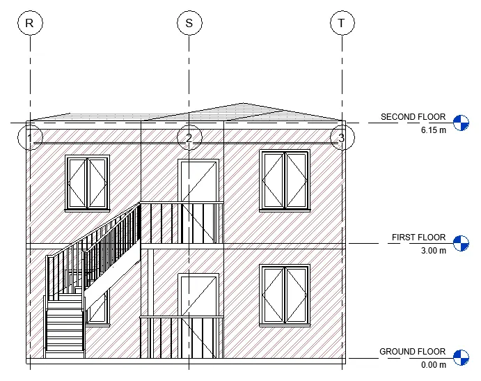
- Again, go to view tab, select the drop down of the elevation tool from create panel and inset the elevation view icon at the right side of plan.
- Go to the property browser and rename it as West as shown below.
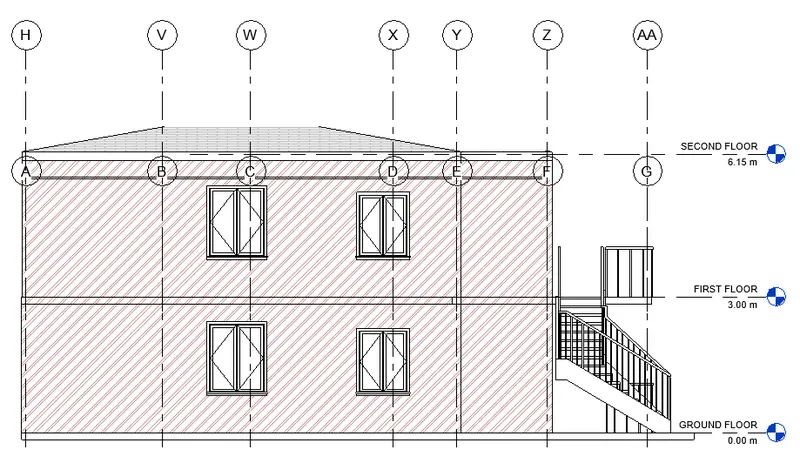
- Again, go to view tab, click on drop down of elevation tool from create panel, select the elevation option and place the elevation icon at down side of the plan.
- Go to the project browser and rename it as North.
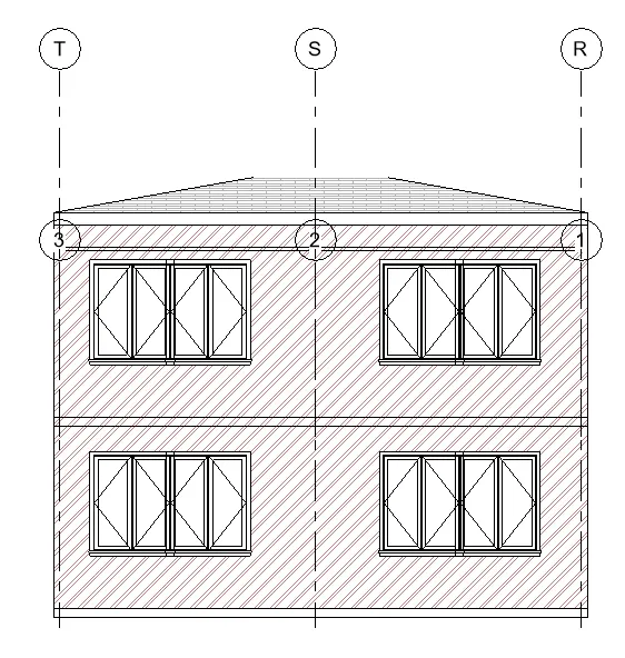
- Again, go to view tab, click on drop down of elevation tool from create panel, select the elevation option and place the elevation icon at left side of the plan.
- Go to the project browser and rename it as East.
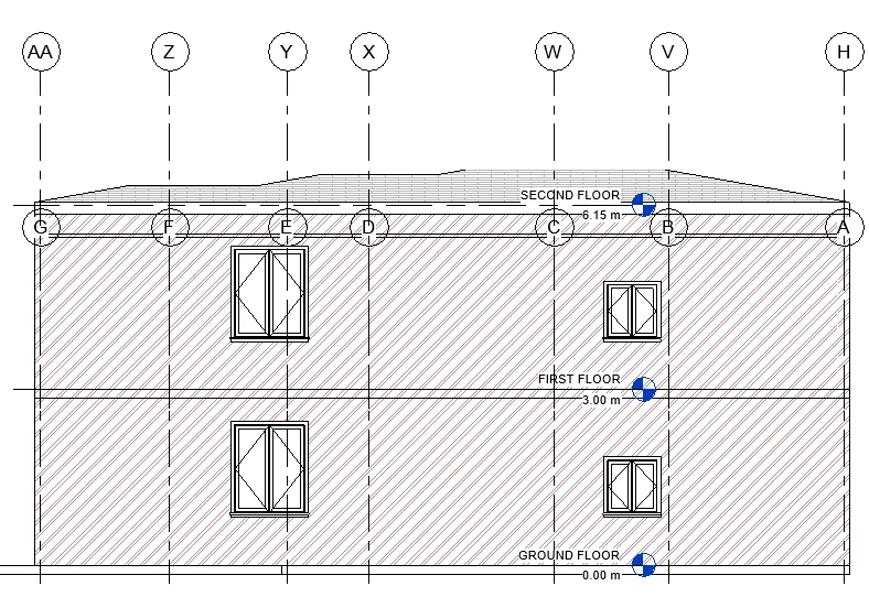
RESULT:-
Therefore, the east, north, south and west elevation views are created in Revit software by following the above mentioned procedure as shown below.
East Elevation View:-
North Elevation View:-
South Elevation View:-
West Elevation View:-
_____________________________________________________________________________________________________
7. Produce section cut through each room either cutting across longitudinally or in a transverse direction
AIM:- To produce a section cut through each room either cutting across longitudinally or in transverse direction in Revit software.
INTRODUCTION:-
- A sectional view or a section looks inside an object. Sections are used to clarify the interior construction of a part that cannot be clearly described by hidden lines in exterior views. By taking an imaginary cut through the object and removing a portion, the inside features may be seen more clearly.
- Section views are used in technical drawings to expose internal surfaces.
- They servers to present additional orthographic views of surfaces that appears as hidden lines in the standard front, top, and side orthographic views.
- Section views are added in Revit software by using section tool of view tab.
PROCEDURE:-
- Open rivet software, select the residential unit file from Revit homepage to open it.
- Double click on the ground floor plan from project browser to open the view.
- Go to view tab,select the section tool from create panel.
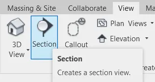
- Create a panel cut the longitudinal section through the living room.
- Go to project browser, select the section view, right click on it and rename it as HALL section.
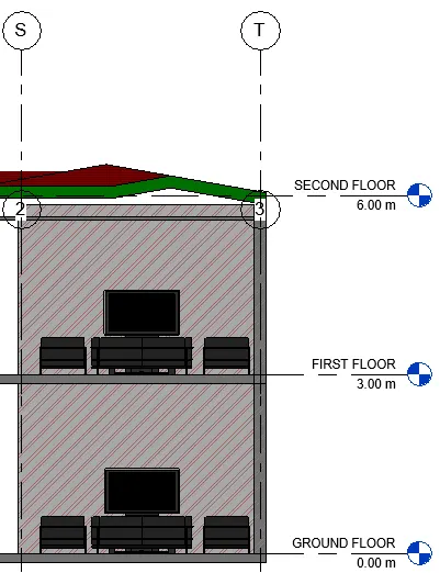
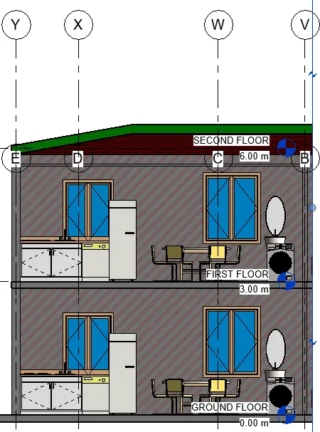
- For cutting section through kitchen cum dinning room, again go to view tab, select the section tool, draw the transverse section line through kitchen cum dinning room as shown below.
- Go to project browser, select the section view, right click on it and rename it as KITCHEN CUM DINNING section.
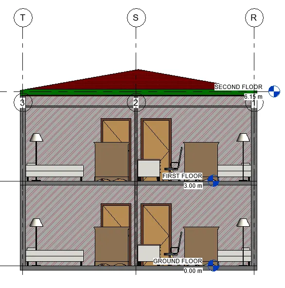
- For creating section view of bedroom, go to view tab, select the section tool from create panel, cut the longitudinal section through the bed room.
- Go to project browser, select the section view, right click on it and rename it as BEDROOM section view.
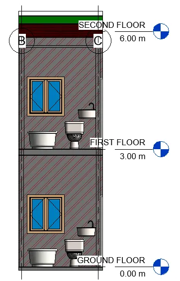
- For creating section view of bathroom, go to view tab, select the section tool from create panel, cut the longitudinal section through the bathroom.
- Go to project browser, select the section view, right click on it and rename it as BATHROOM section view.
- similarly create the section in such a way that left side section is viewed. where stairs and kitchen are seen and rename the section view as STAIRS & KITCHEN using project browser.
- In project browser, we can see the different sections, whatever is created.
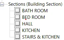
- In plan view different views are created. The snap is plan view in HIDDEN view with different is as follows:-
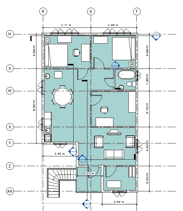
RESULT:-
Therefore, the section cuts are produced through each room in longitudinal and transverse direction in Revit software as shown below.
Realistic section view of HALL:-
Realistic section view of KITCHEN CUM DINNING:-
Realistic section view of BEDROOM:-
Realistic section view of BATHRROM:-
Realistic section view of STAIRS & KITCHEN:-
_____________________________________________________________________________________________________
8. Classify the views, Plan Views, Section Views, and Elevation views to either Design or Documentation category using Properties browser
AIM:- To classify the views, Plan Views, Section Views, and Elevation views to either Design or Documentation category using Properties browser.
INTRODUCTION:-
- The structural plan view is the default view when you start a new project using a structural template.
- Most projects include at least one structural plan. New structural plan views are created automatically as you add new levels to your project. You can create multiple structural plan view types.
- The floor plan view is the default view in a new architectural project. Most projects include at least one floor plan.
- Floor plan views are created automatically as you add new levels to your project.
- Sectional views reveal hidden details in a mechanical drawing.
- These views assume that a cutting plane has removed portions of the object represented by the drawing, displaying the appropriate section of the interior.
- Sectional views are used in engineering and architectural drawings.
- They help civil engineers, architects, and airplane designers communicate their ideas to their peers.
- An elevation is a view of a building seen from one side, a flat representation of one view.
- This is the most common view used to describe the external appearance of a building.
- Each elevation is labelled in relation to the compass direction it faces, e.g. looking toward the north you would be seeing the southern elevation of the building.
- Various views are created in Revit software such as plan view, elevation view, section views, etc, which are helpful to presentation of the details of the project.
- After creating the specific view using the corresponding tool of Revit software, the view is automatically added in the project browser to asses the view.
PROCEDURE:-
- The views are classified as Structural plan views, Floor plan views, Ceiling plans, 3D views, Elevations, Sections, Rendering views, Area plans.
- Structural plan view consist of all the structural components such as structural wall, columns, stairs, floors, beams etc.
- In Revit software structural plan views are created using plan view tool of view tab under the type structural plan view.
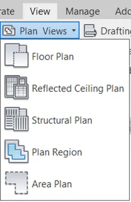
- After creating the structural view, the view is automatically added in the project browser.
- Floor plan view consists of all the Architectural floor plan view which includes all the structural such as walls, columns, floors and architectural components, furniture, doors, windows etc.
- In Revit software floor plan views are created using plan view tool of view tab under the type floor plan.
- Ceiling is an overhead interior surface that covers the upper limits of a room.
- Ceiling is not generally considered as structural element but a finished surface concealing the underside of the roof structure or floor of story above.
- To model a ceiling, the ceiling tool from architecture tab is used.
- 3D views are virtual representation of building which helps to predict the futural realistic view of the buildings.
- 3D views in the Revit software are created by placing the camera at appropriate position to get the camera specific views.
- Elevation views are the view of the building seen from one side such as north, south, east or west side.
- Elevation views are created using the elevation tool of the view tab from create panel and can be obtained from project browser.
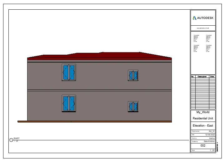
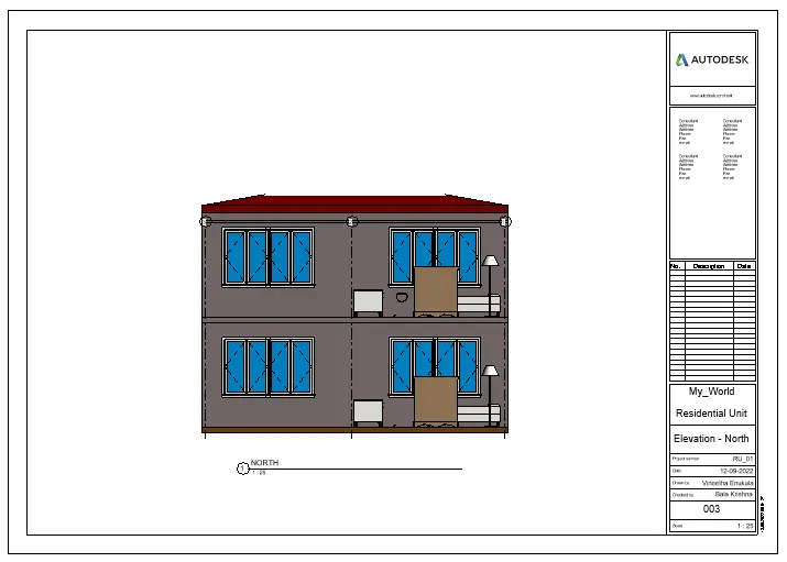
- Section views are used in technical drawings to expose internal surfaces.
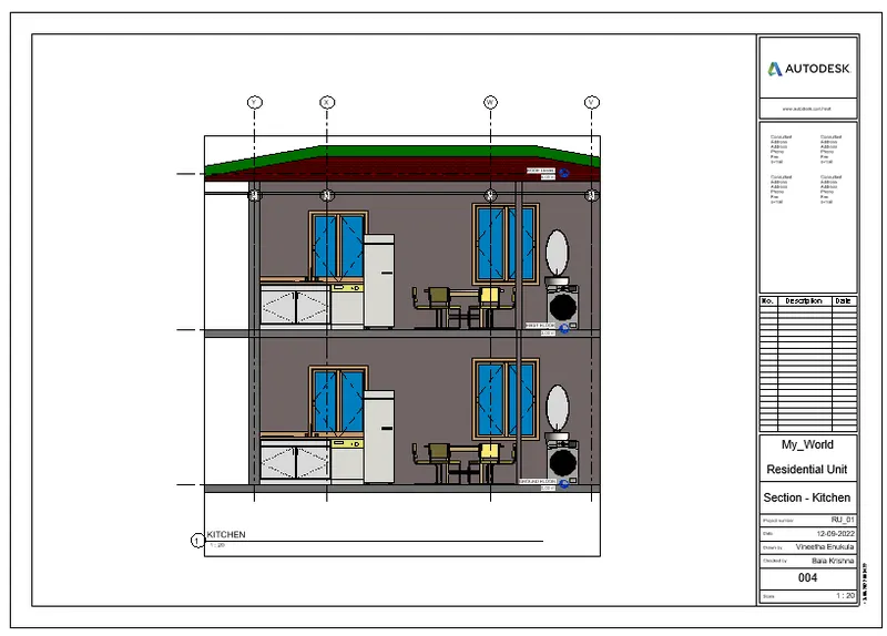
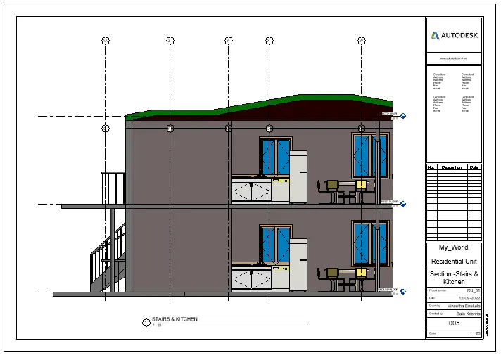
- They servers to present additional orthographic views of surfaces that appears as hidden lines in the standard front, top, and side orthographic views.
- Section views are added in Revit software by using section tool of view tab and can be seen using the project browser.
- Rendering views are views that are added in the list if we render camera specific view and save the view in the project.
- Rendered views are the more realistic views of the building which are created using render tool from view tab from the presentation panel.
- Area plans are the plans that only represent the area of the building.
- Area plans are created using the plan view tool of the create panel of the view tab and added in project browser automatically after creating view.
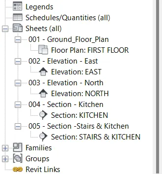
- Various views classified in the Revit software are specified in the project browser as shown below.
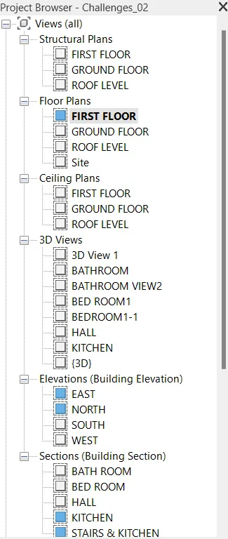
RESULT:-
Therefore, various views such as plan views, elevation views, section views which can be created in Revit software are classified above and added can be shown on the project browser as shown below.
_____________________________________________________________________________________________________
9. Using the sheet template produced create multiple sheets as follows
a. A 101- Ground Floor Architecture Plan
b. A 102- First Floor Architecture Plan
c. A 103- Roof Plan
d. S 101- Ground Floor Structural Plan
e. S 102- First Floor Structural Plan
f. S 103- Roof Framing Plan
g. A-201- North-South Elevations
h. A-202- East-West Elevations
Add additional sheets based on the sections created in your Revit file
AIM:- To create multiple sheets using sheet template and add different views in Revit software.
INTRODUCTION:-
- Create views on a project template before you start building the model to streamline the project documentation process.
- When creating a project template, you can include sheets in the template. Start with a blank project file, and create the standard views and levels that each project should include.
- Leave the views empty, but assign standard names to them. To create a standard set of construction documents, create sheets using the desired title blocks.
- Add views to the sheets, using the desired viewport templates and view title types.
- Then save the empty project as a project template.
- When you create a project using this project template, all of the views and sheets are already created and listed in the Project Browser.
- As you start to draw the building model in the project views, the views on the sheets update automatically.
- This technique streamlines the project documentation process and maintains organizational standards.
- A template is a predesigned spreadsheet that can be used to create new spreadsheets with the same formatting and predefined formulas.
- Sheet template is created using sheet tool of view tab.
- Various views are added in the sheets by dragging the view from project browser using the mouse.
PROCEDURE:-
- Open rivet software, select the residential unit file from Revit homepage to open it.
- For creating the sheet, go to view tab, select the sheet tool from sheet composition panel, it will open the new sheet dialog box.
- Select the sheet paper size as A1 and select ok from dialog box, it will open the created sheet template as shown below.
- To adjust the parameters on the sheet double click on the parameter and change it as per the required value as shown below or Go to toolbar - Mange - Project Information tab, click on it. Dialogue box appers on screen, there rename the text as per requirement and then click on apply and then click on ok.
- By that automatically the sheet information got changed.
- Similarly change all the parameters as per desired value as shown below.
- To change the name of sheet double click on name and change it as 001.
- Similarly double click on the sheet number and change it as 001 as shown below.
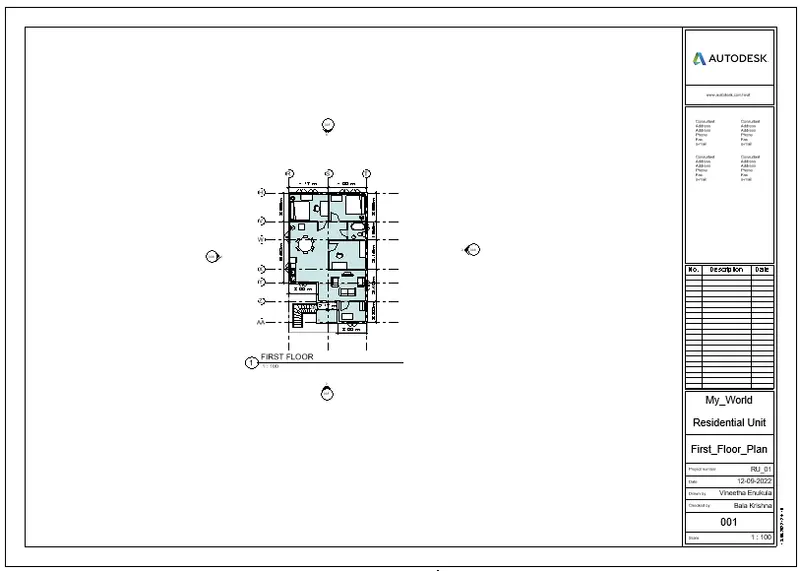
- Select the architectural first floor plan view from project browser and drag the view in the sheet using mouse.
- Change the scale of the view using property window to fit the view into the sheet as shown below.
- Again go to view tab, select the sheet tool, and add the sheet as explained above or make a duplicate sheet.
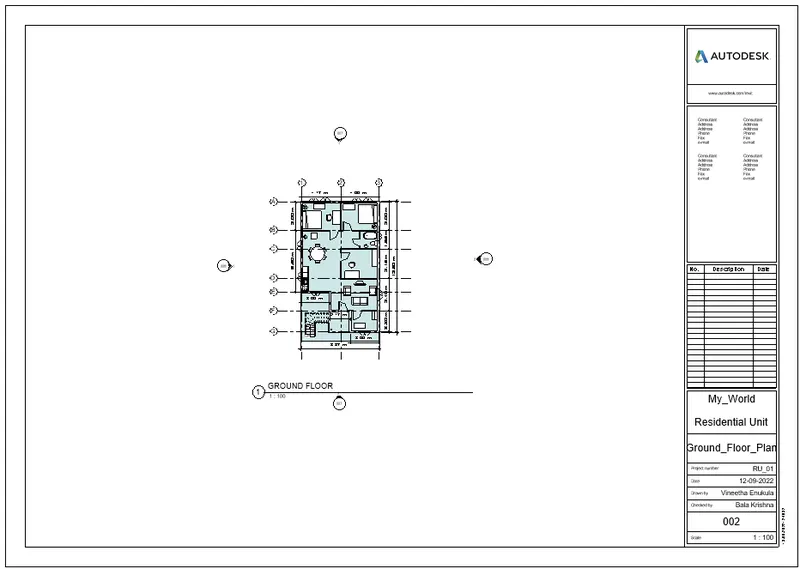
- To change the name of the sheet double click on the name and edit it as 002.
- Go to the property browser, select the architectural ground floor plan view, drag the view into the sheet, change the scale of the view such that the view fits into sheet from the property window as shown below.
- In roof plan,
- Again go to view tab, select the sheet tool, and add the sheet as explained above.
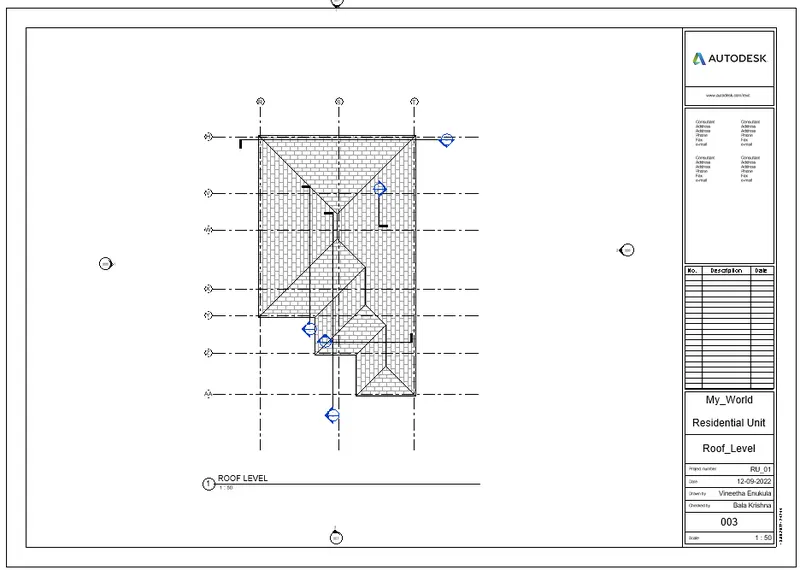
- To change the name of the sheet double click on the name and edit it as 003
- Go to the property browser, select the architectural roof framing plan view, drag the view into the sheet, change the scale of the view such that the view fits into sheet from the property window as shown below.
- Similarly add the sheet as explained above using the sheet tool from view tab and edit the name of sheet as 005.
- Go to the property browser, select the ground floor structural plan view, drag the view into the sheet, change the scale of the view such that the view fits into sheet from the property window as shown below.
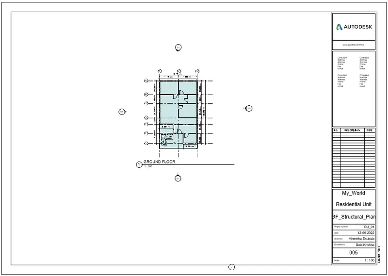
- Similarly add the sheet as explained above using the sheet tool from view tab and edit the name of sheet as 004.
- Go to the property browser, select the first floor structural plan view, drag the view into the sheet, change the scale of the view such that the view fits into sheet from the property window as shown below.
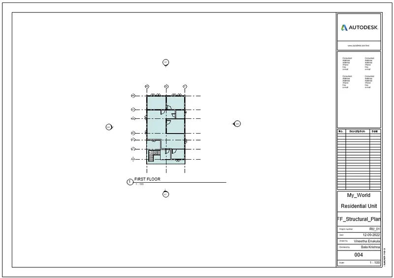
- Similarly add the sheet as explained above using the sheet tool from view tab and edit the name of sheet as 006.
- Go to the property browser, select the roof framing structural plan view, drag the view into the sheet, change the scale of the view such that the view fits into sheet from the property window as shown below.
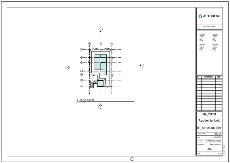
- Similarly add the sheet as explained above using the sheet tool from view tab and edit the name of sheet as 007.
- Go to the property browser, select the north elevation view, drag the view into the sheet, change the scale of the view such that the view fits into sheet from the property window as shown below.
- Similarly add the south elevation view in the same sheet by dragging it from project browser as shown below.
- Similarly add the sheet as explained above using the sheet tool from view tab and edit the name of sheet as 007.
- Go to the property browser, select the north elevation view, drag the view into the sheet, change the scale of the view such that the view fits into sheet from the property window as shown below.
- Similarly add the south elevation view in the same sheet by dragging it from project browser as shown below.
- Similarly add the sheet as explained above using the sheet tool from view tab and edit the name of sheet as 008.
- Go to the property browser, select the east elevation view, drag the view into the sheet, change the scale of the view such that the view fits into sheet from the property window as shown below.
- Similarly add the west elevation view in the same sheet by dragging it from project browser as shown below.
- Similarly add the section view in the sheet naming as 009 as shown below.
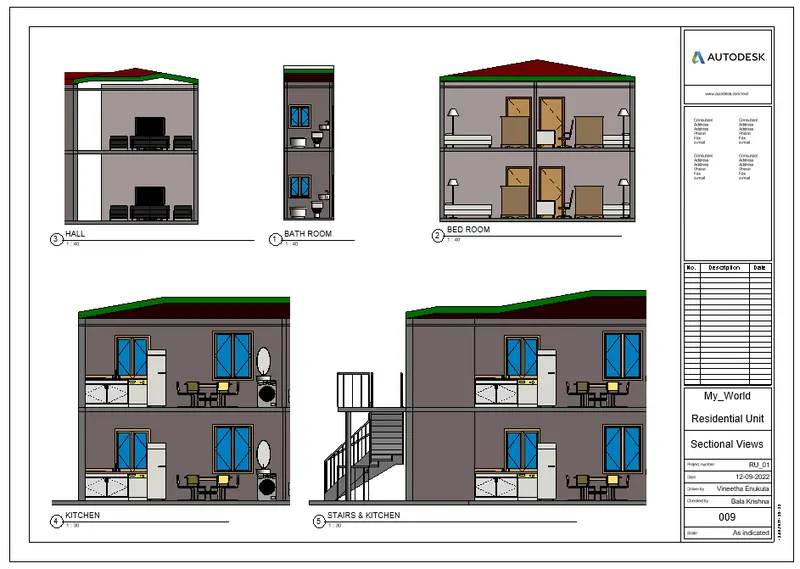
RESULT:-
Therefore sheets are created and renamed with the required name in Revit software as shown below.
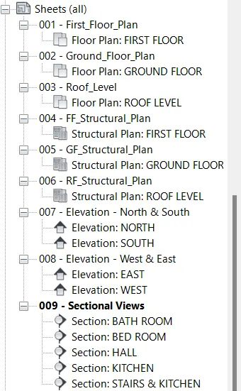
- 001 - Ground Floor Architecture Plan
- 002 - First Floor Architecture Plan
- 003 - Roof Level Architectural Plan
- 005- Ground Floor Structural Plan
- 004- First Floor Structural Plan
- 006- Roof Framing Plan
- 007- North-South Elevations
- 008- East-West Elevations
- 009- Additional section view sheet
_____________________________________________________________________________________________________
10. Create a camera-specific view or a 3D view in each room ( living, dining, bedroom). Based on the views create a new set of sheets starting A-501 (you can add as many sheets after, 502, 503.. n)to place the 3D view images. Produce the sheets as a part of project drafting.
AIM:- To create a camera specific view or 3D view in each room and set the sheets staring from A-501 as a pert of project drafting in Revit software.
INTRODUCTION:-
- 3D views are virtual representation of building which helps to predict the futural realistic view of the buildings.
- 3D views in the Revit software are created by placing the camera at appropriate position to get the camera specific views
- Camera Views are really useful in Revit.
- They allow us to view what we would actually see if we were standing at any given location in our design.
- This can be invaluable for both understanding and communicating the nature of a space before we go to the expensive lengths of actually constructing it for real.
PROCEDURE:-
- Open rivet software, select the residential unit file from Revit homepage to open it.
- For creating the sheet, go to view tab, select the sheet tool from sheet composition panel, it will open the new sheet dialog.
- Select the sheet paper size as A1 and select ok from dialog box, it will open the created sheet template as shown below.
- To adjust the parameters on the sheet double click on the parameter and change it as per the required value as shown below or Go to toolbar - Mange - Project Information tab, click on it. Dialogue box appers on screen, there rename the text as per requirement and then click on apply and then click on ok.
- By that automatically the sheet information got changed.
- Similarly change all the parameters as per desired value as shown below.
- To change the name of sheet double click on name and change it as 010.
- Similarly double click on the sheet number and change it as 010 as shown below.
- Next go to the floor plan and place the camara in the bed room, and the camera view of bed room will be shown below.
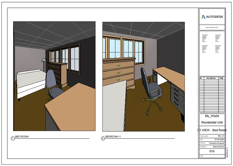
- Next we take the sheet and name it as 011.
- Next go to the floor plan and place the camara in the Hall, and the camera view of Hall will be shown below.
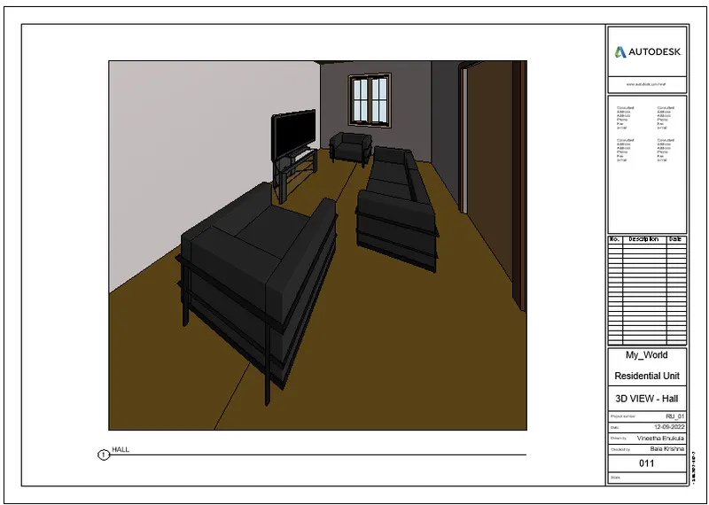
- Next we take the sheet and name it as 012.
- Next go to the floor plan and place the camara in the Kitchen room, and the camera view of kitchen room will be shown below.
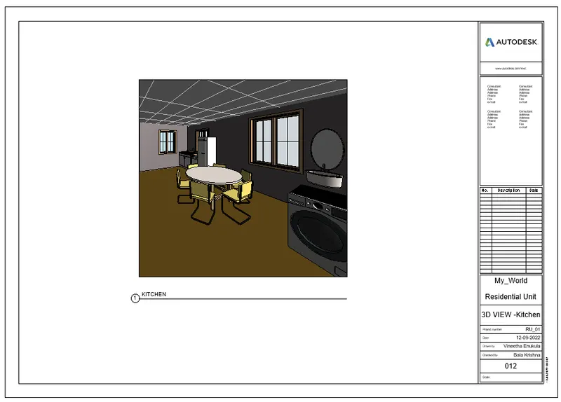
- Next we take the sheet and name it as 012.
- Next go to the floor plan and place the camara in the Bathroom, and the camera view of Bathroom will be shown below.
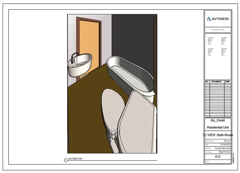
- Next we take the sheet and name it as 014.
- Next go to the floor plan and place the camara in the 3d view of the entite building, and the camera view of 3d view of the entite building will be shown below.
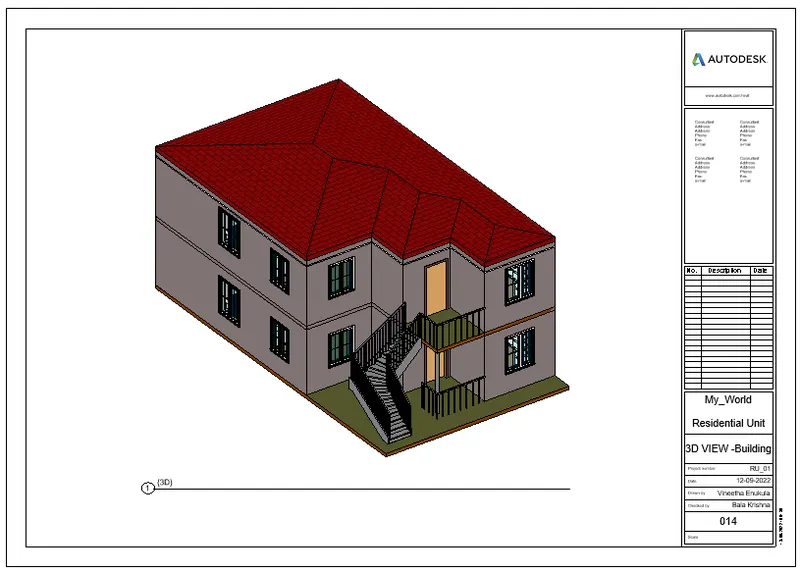
RESULT:-
Therefore, camera specific 3D view in each room are created and set as a sheet starting from A-501 as a part of project drafting in Revit software by using above mentioned procedure as shown below.
Sheet of camera specific realistic view of Bedroom
Sheet of camera specific realistic view of Hall
Sheet of camera specific realistic view of Kitchen
Sheet of camera specific realistic view of Bathroom
Sheet of camera specific realistic view of Entire Building:-
______________________________________________***THE END***__________________________________________