3D Creation of Celing, Roof, Architectural plan, Structural plan, Sectional view, Elevation view and Camera specific view for a house plan using REVIT
CHALLENGE WEEK - 4
REVIT
Question no. 1: Based on the project saved from Week 3, proceed from the First Floor Level. Model a Ceiling from the architecture tab above the walls at the first-floor level
- Aim:
- To create a ceiling.
- The ceiling to be created in first floorlevel.
- Procedure:
- To create a ceiling.
- The celing is to be created in the residential plan created before.
- After opening the model created.
- We need to go the architectural; tab.
- Then need to select the ceiling creation tool present in the tool bare.
- After selecting the tool.
- Select the boundries that the ceiling to need to cover over the walss.
- The boundaries can be selected either by draw tool or by pick lines.
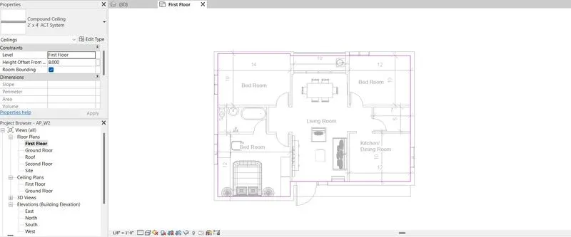
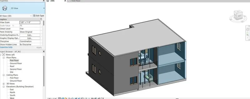
- And the ceiling on the first floor was created.
- Result:
- Thus the ceiling on the first floor was created
- The material and thickness of the ceiling were changed.
Question no. 2: Model a roof above the ceiling by selecting the footprints of the ceiling. Using the adjustment toolbars appearing on-screen adjust the roof slope to 10 degrees.
- Aim:
- To create a roof.
- The roof to be created is using footprint.
- Procedure:
- To create a roof.
- The roof is to be created in the residential plan created before.
- After opening the model created.
- We need to go the architectural tab.
- Then need to select the roof creation tool present in the tool bar.
- Whne the selecting the tool we get to see a drop down panel.
- And we need to select the option called roof by foortprint.
- Then the boundries of the roof is to be created.
- Then the edges of the boundry where we require angle is to be selected and angle is given.
- Then after selecting the finish option w can see tehcreated roof.
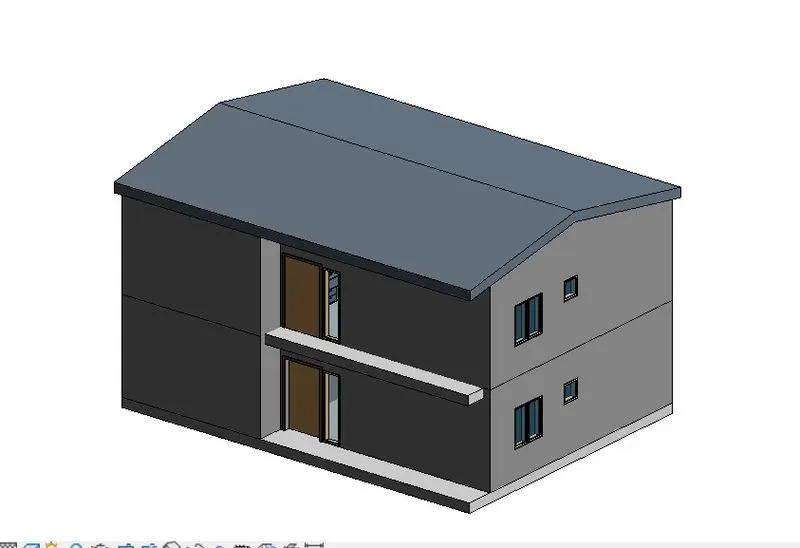
- Thus the desired roof was created with required slope.
- Result:
- Thus the desired roof was created with required slope.
- The material and thickness of the roof were changed.
Question no. 3: Using the file saved from weeks 2 to 4, create plan views for ground floor level and first-floor level including all the walls, floors, and components. Separate them to
architecture and structural plans
a. Architecture plan must have walls, floors, and all the components placed within the building
b. Structure plan must have details of only walls, floors, and columns
- Aim:
- To create a plan views on architectural and structural.
- Procedure:
- Initially go the created model.
- then select teh view tab in the tool tab.
- Then go to the plan view tab.
- After which you can see a drop down panel.
- In that drop down panel select the required plan view to be brought to the prooject browser.
- Then open the view from the project browser.
- Fir the architectural plans are shown below.
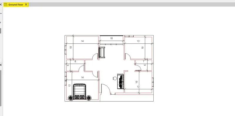
- Then the structural plan view is shown below.
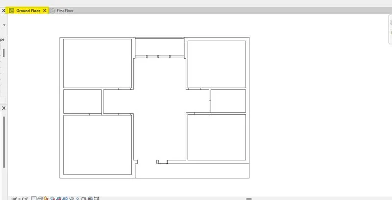
- Thus the plan views were created.
- Result:
- Thus the plan views were created.
Question no. 4:Using annotate toolbar add dimensions to all the walls and floors with reference to the longitudinal and transverse grids created in the project file
a. The architecture plan dimensions include details on where the components are placed within the buildings with relation to grids. Overall dimensions are sufficient for architecture plans
b. The Structure plan dimensions must include details on the position of all the walls and interior walls with reference to grids. Locate all the framing components of the building with reference to a fixed point using Structural plans
- Aim:
- To create annotations.
- Procedure:
- Initially go to the created model.
- And use the created plan views.
- The plan views such as the architectural and the structural plan views are to be used.
- Then open any of the plan views first.
- The annotation categories are chose from the anootate tab in the tools tab.
- Then the required annotation tool is chose.
- And then thr dimension of the corresponding regions are marked.
- First architectural template was opened and the dimesions of the plan was marked and shown.
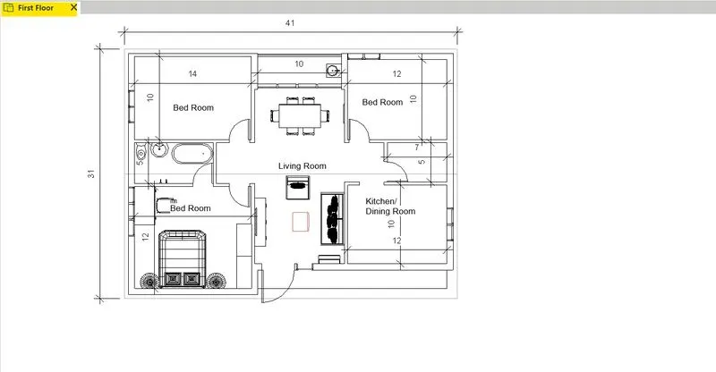
- Then the plan view of the structural plan was opened and the dimesions for the plan was marked.
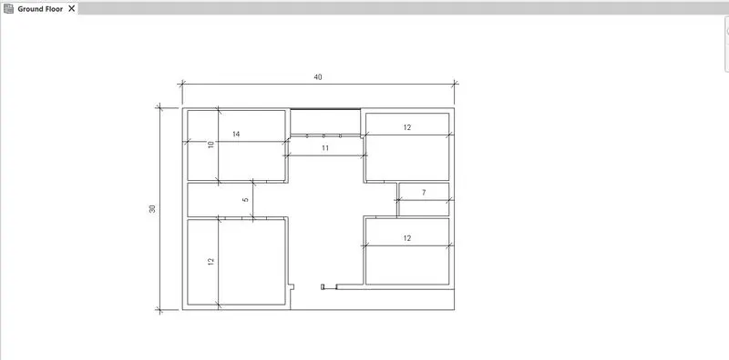
- Thus the annotation for the created plan views were done.
- Result:
- Thus the annotation for the created plan views were done.
Question no. 5: Create a sheet template from the view tab and adjust the parameters on the sheet to add appropriate views
- Aim:
- To create sheet template
- To adjust parameter on the sheet.
- Procedure:
- Initially go to the created model.
- And need to open the view tab
- In the view tab there is a icon showing sheets creation.
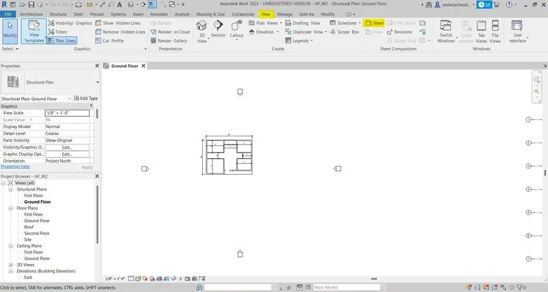
- After selecting the sheets tab.
- We can choose the sheets that is required for the project.
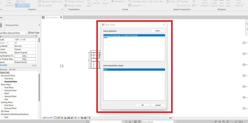
- After the sheet being chosen, we get a sheet in the page. Which can be renamed as per required standards.
- Then the required parameters are filled in the project.
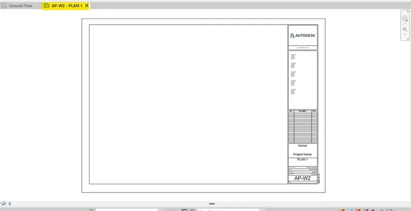
- And the required view is added to the sheet.
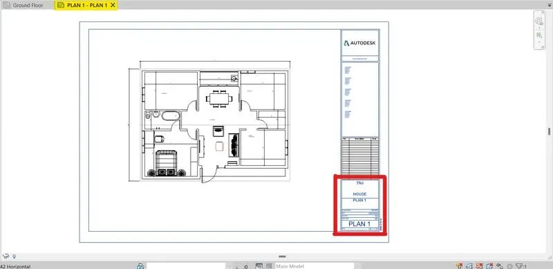
- And the parameters relating to the view and the project was added to the sheet.
- And thus the sheet was created, view was created and the project informations were updated.
- Result:
- Thus the sheet was created, view was created and the project informations were updated.
Question no.6: Using the elevation tab create the elevation views, looking at your building from East, North, South, and West
- Aim:
- To create elevation views.
- Procedure:
- Initially go to the created model.
- And need to open the view tab
- In the view tab there is a icon showing elevation logo.
- Need to pick those logo.
- Then place the logo in the required positions.
- Such that the elevation view shows required view.
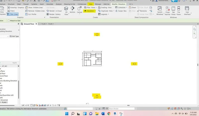
- Above shown are steps and the elevation logos placed.
- Then the views chose are shown
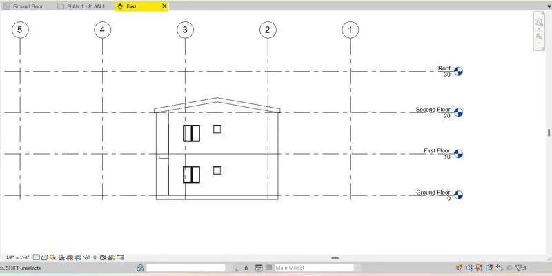
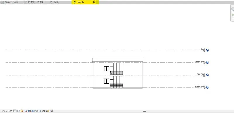
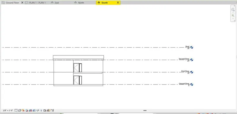
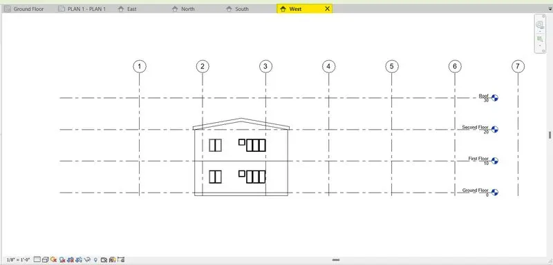
- And all the views (North,South , East and West) were shown in above clippings.
- Result:
- Thus the elevations were created and the views of the elevations were shown
Question no. 7: Produce section cut through each room either cutting across longitudinally or in a transverse direction
- Aim:
- To create sections
- To cut across each room.
- Procedure:
- Initially go to the created model.
- And the top tool bar we have section logo.
- After opening the section.
- Need to draw the section lines across teh required places.
- And then need to select the drawn section lines to view the section.
- The created sections are shown below.
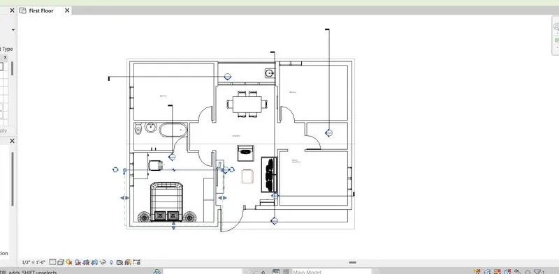
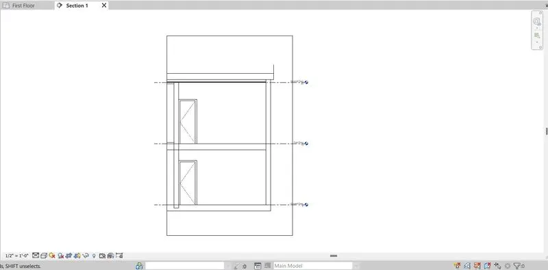
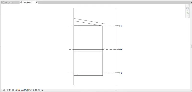
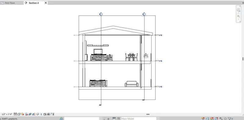
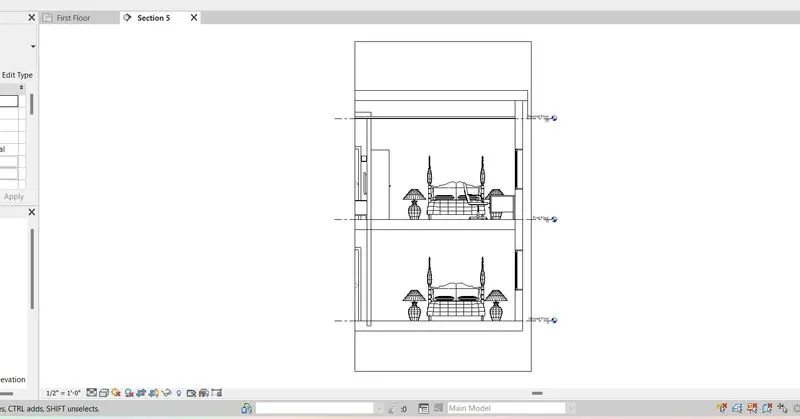
- Hence the sectional views were created.
- Result:
- Thus the section lines were drawn across each room.
- The created sections were shown as view.
Question no. 8: Classify the views, Plan Views, Section Views, and Elevation views to either Design or Documentation category using Properties browser
- Aim:
- To classifies views
- Procedure:
- Initially go to the created model.
- Then open the project browser on the workplane.
- Afterwhich we can find the porject browser on the interfasce.
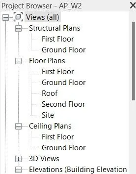
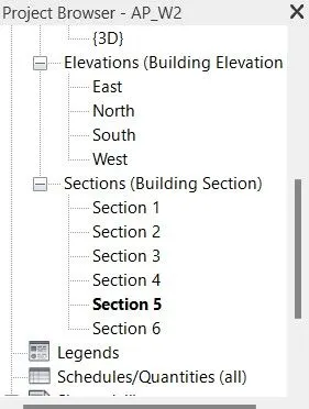
- Then the views such as
- Plan views, Section views adn elevation views are seen.
- These views are classiefied and shown below.
- Result:
- Thus the views were classied..
- The classified views were shown.
Question no. 9: Using the sheet template produced create multiple sheets as follows
a. A 101- Ground Floor Architecture Plan
b. A 102- First Floor Architecture Plan
c. A 103- Roof Plan
d. S 101- Ground Floor Structural Plan
e. S 102- First Floor Structural Plan
f. S 103- Roof Framing Plan
g. A-201- North-South Elevations
h. A-202- East-West Elevations
- Aim:
- To create sheets.
- To follow suggested conditions.
- Procedure:
- Initially go to the created model.
- And need to open the view tab
- In the view tab there is a icon showing sheets creation.
- After selecting the sheets tab.
- We can choose the sheets that is required for the project.
- And the slected views are shown below.
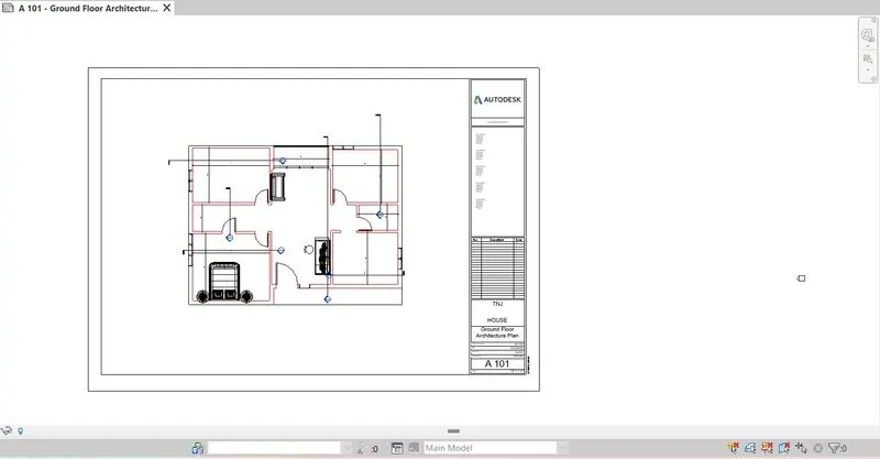
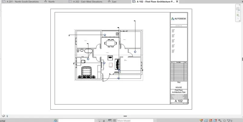
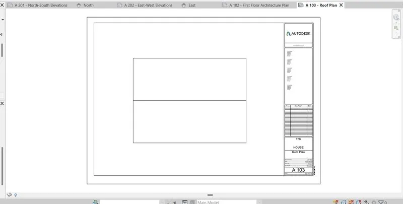
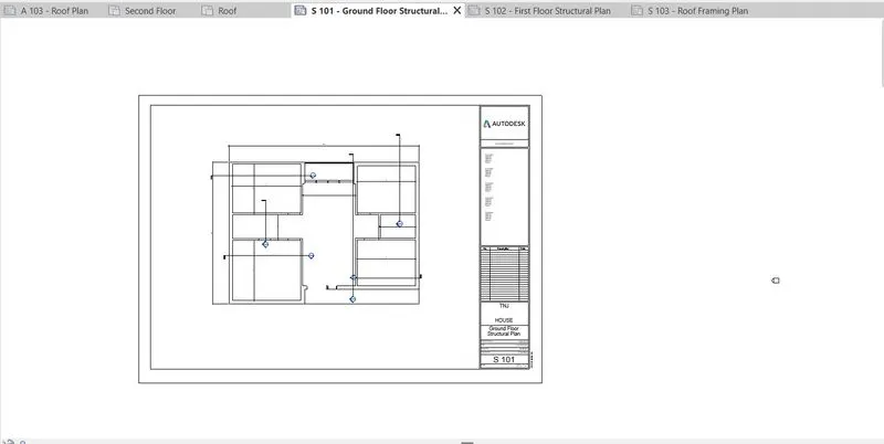
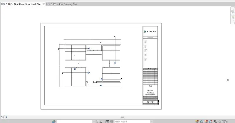
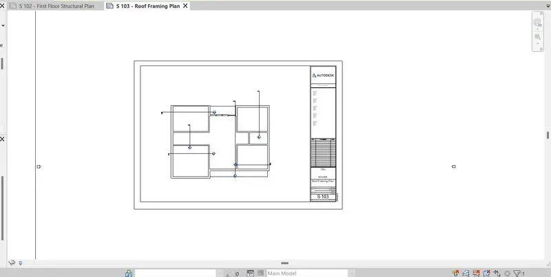
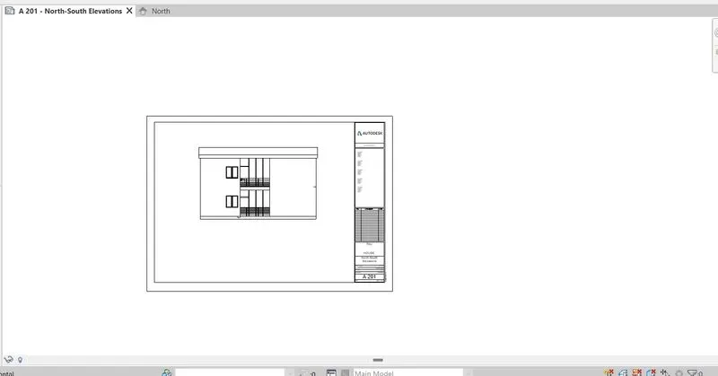
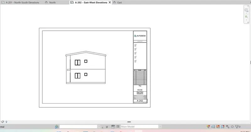
- Result:
- Thus all the sheets were created.
- The suggested conditions were followed.
Question no. 10: Create a camera-specific view or a 3D view in each room ( living, dining, bedroom). Based on the views create a new set of sheets starting A-501 (you can add as many sheets after, 502, 503.. n)to place the 3D view images. Produce the sheets as a part of project drafting.
- Aim:
- To create a camera specific view.
- To crate view to the sheet
- Procedure:
- Initially go to the created model.
- Then open the view tab from the tool bar tab.
- Then the slect the view creaation such as 3d view, camera or walkthrough.
- Select camer.
- And then place the camer at required positions.
- Thus created views are shown below.
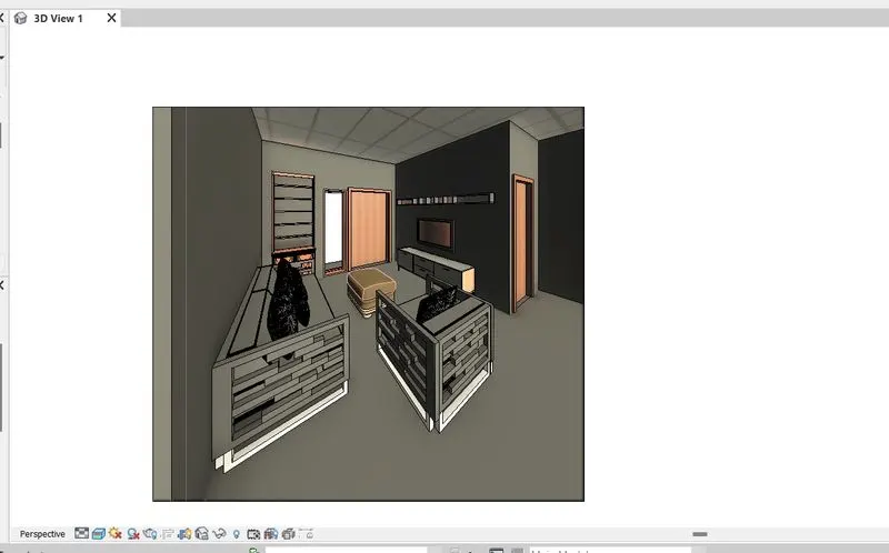
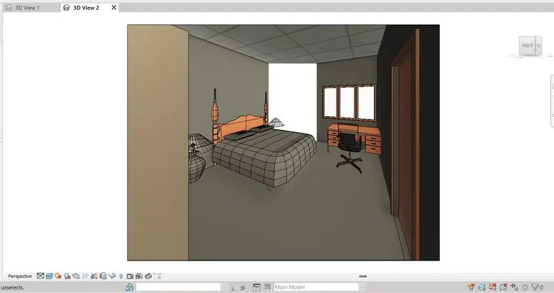
- Then after creating the views.
- These views were added to the sheet.The sheets were named according the requirement
- The created sheets are shown below.
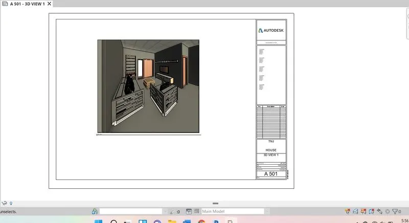

- Result:
- Thus the camera was set and views were created.
- And the sheets for the views were created.