3D Creation of Celing, Roof, Architectural plan, Structural plan, Sectional view, Elevation view and Camera specific view for a house plan using REVIT
3D Creation of ceiling, Roof, Architectural plan, Sectional view, Elevation view and Camera specific view for house plan using the REVIT
INTRODUCTION:-
Inorder to create the ceiling and roof for a building using revit software following steps can be followed:
- Ceiling: Open revit software àArchitecture tab à
- Roof: Open revit softwear à Architecture tab à
Architecture plan, structural plan, sectional view and elevation view can be developed from the view tab.
- Ribbonà viewàplan views: choose any of the plans like floor plan, structural plan etc.
- Sectional view can be developed as follows – ViewàCreate panelàsectionàthen we have to mark where the section is to be created.
- Elevation: viewà Create panelà elevation views.
AIM 1:-
To create the ceiling above the walls at the first floor level.
PROCEDURE:-
- Initially open the week 3 assignment from the revit software.
- Then, first let us create a verandah in the ground floor as well as first floor level so that roof can be created for the entire structure.
- For this initially go to plan view.
- Then using the floor option create the floor for the verandah portion as given
- Now, copy this floor to the level 2 i.e, the first floor level.
- Now we have to create a column for the verandah at the ground floor.
- Next we have to create the railing for the first floor verandah.
- For this go to railing option in this the architecture tab and create the railing.
- Now we can place the ceiling for this go to architectural tab and choose ceiling
- Ceiling is to be provided in the level 2 for the ground floor.
RESULT:-
Hence, the ciling is created.
AIM 2:-
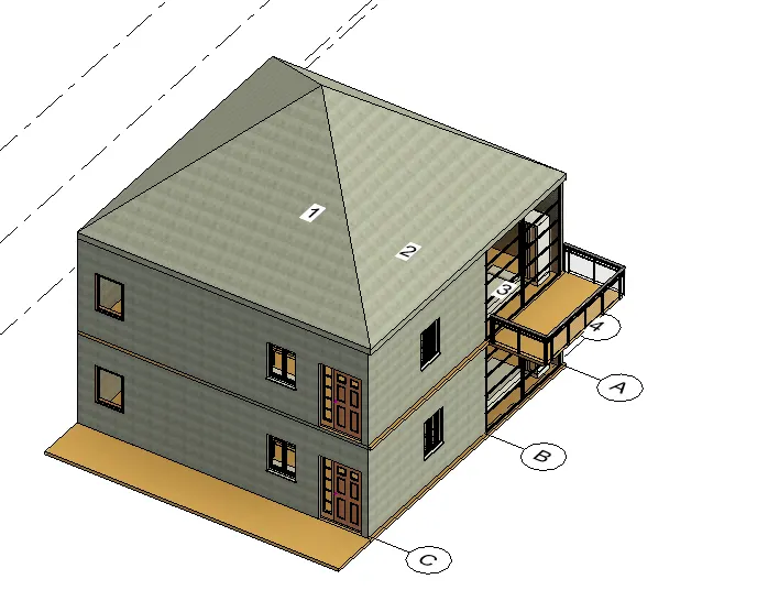
To model a roof above the ceiling by selecting the footprint of the ceiling and to adjust the roof slope to 10 degrees using adjustment toolbar.
PROCEDURE:-
- Inorder to create roof, initilally go to architecture tab of the ribbon.
- Then choose the roof option from the roof dropdown choose roof by footprint.
- Then using the pick wall option in the modify tab create the roof boundry.
- Now,we have to adjust the roof slope to 10 degrees.
RESULT:
Hence,10 degrees slope is created.
AIM 3:-
To create plan views for ground floor and first-floor level including all the walls,floors,and componentsand then separate them to
a)Architecture plan
b)Structural plans.
PROCEDURE :-
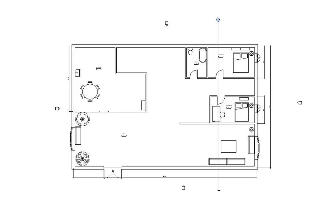
a) To create architectural plan
- Initially go to view tab of the ribbon then select plan views.
- In the plan views, select floor plan.
- Then the floor plan is obtainrd as follows.
b) To create the structual plan; for this the plan will contain only walls floors and the column as the structural elements and is given as floows.
AIM 4:-
To add dimentions to all the walls and floors with reference to the longitudinal and transverse grid create in the project file.
PROCEDURE:-
- Initially select the floor plan for ground floor.
- Go to he annotate tab and choose linear dimension and provide linear line dimension in the plan.
- Now go to architectural tab and choose tag rooms option.
- Then tag the individual rooms as given below.
- Now we have to create the strutural plan dimensions acording to the grid lines.
- For this,go to the structural plan.
- Then go to architectural tab, select grid and draw grids along the walls.
AIM 5:-
To create a sheet templete from the view tab and adjust the parameters on the sheet to add apporpriate views.
PROCEDURE:-
- Initilally go to the view tab to the pannel.
- Choose the option in the sheet composition panel of the view tab.
- Click load option and load more templates.
- Select the templete and click ok.
- Now,choose the view taht is to be added in the templete.
- Add view to the sheet and then adiust the scale so that it fit to the templete.
AIM 6:-
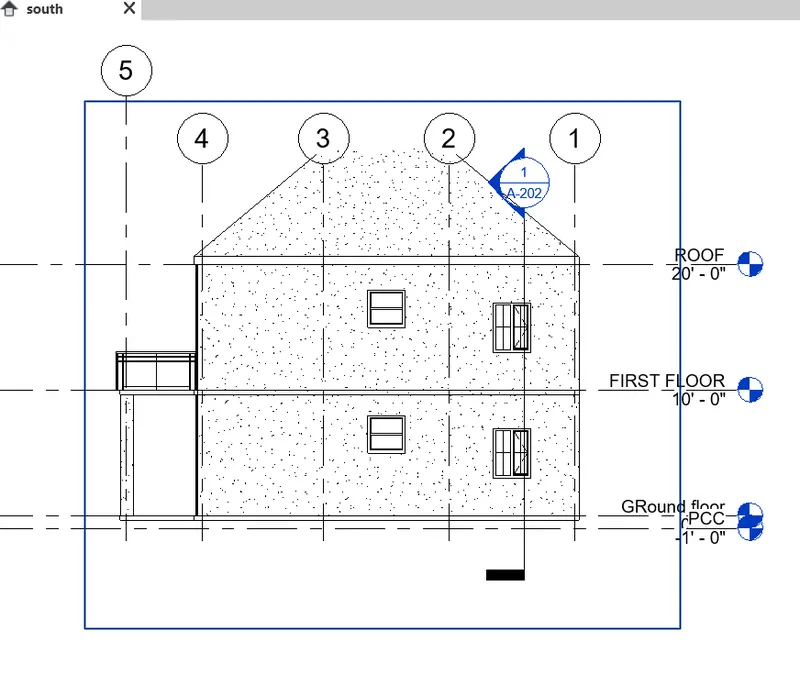
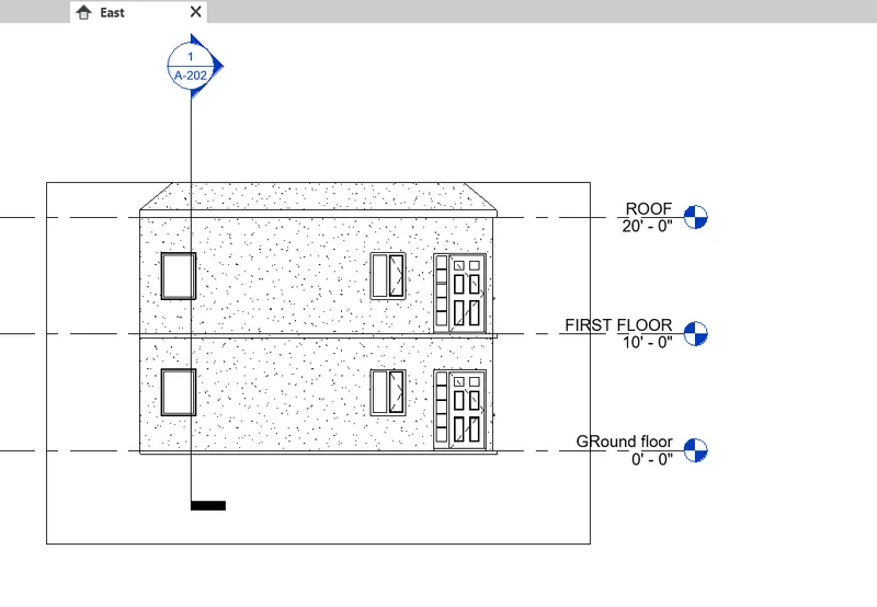
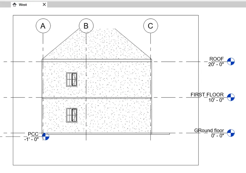
To create the elevation views,looking at your building East, South, and West.
PROCEDURE:-
- Initially go to the view tab of the ribbon.
- Choose elevation view.
- Then create the elevation view--> nort,south.east and west.
- The elevation views thus obtained are:
AIM 7:-
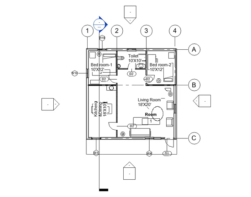
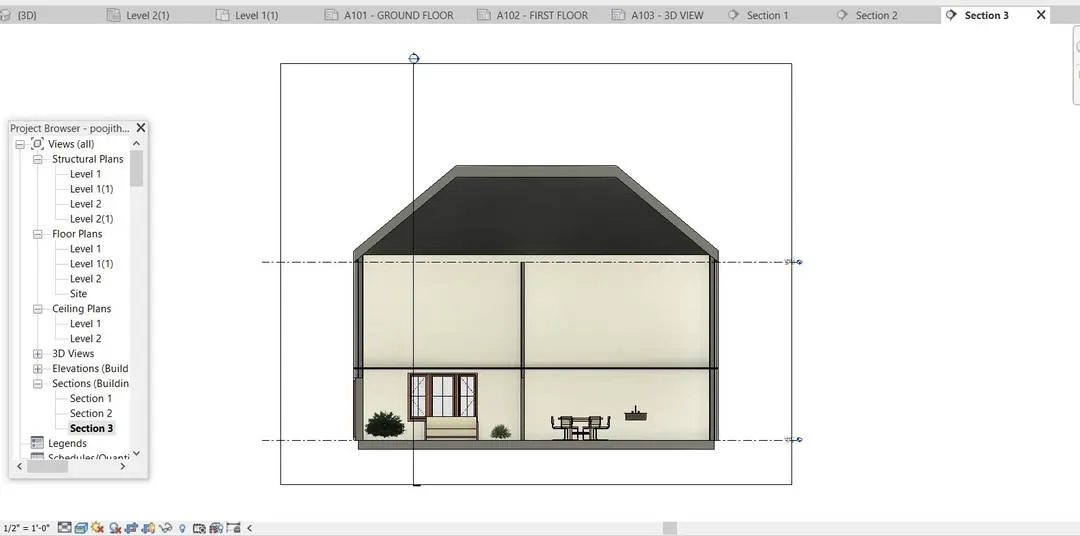
To produce section cut through each room.
PROCEDURE:-
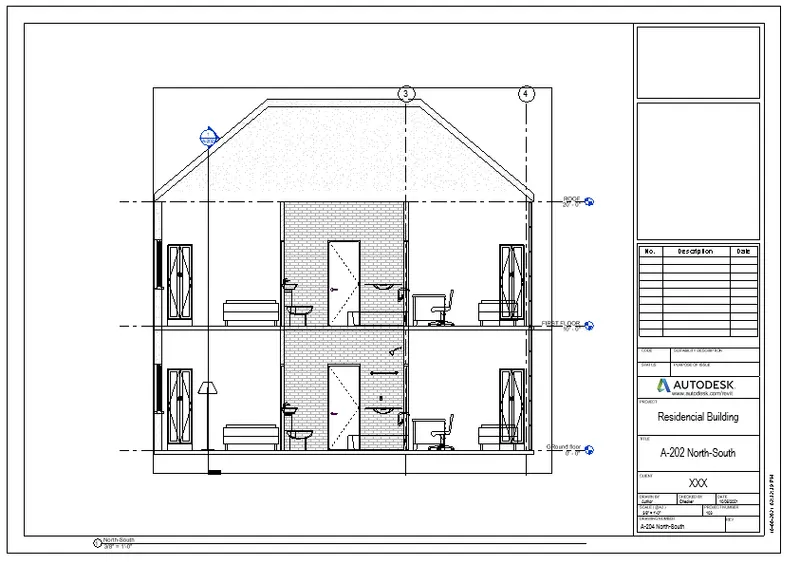
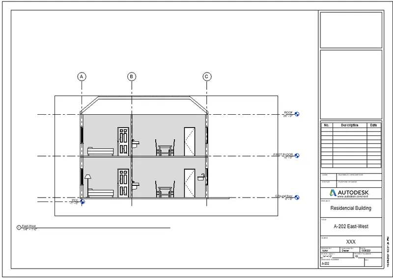
- Go to view tab of the ribbon, select the section view and then select the required room.
AIM 8:-
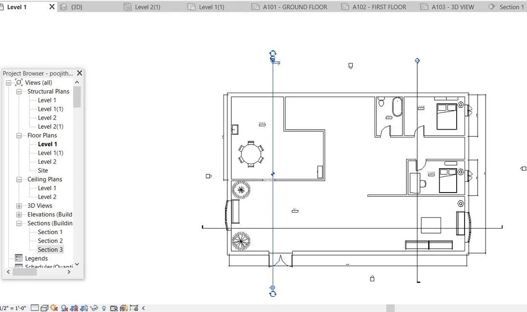
To classify the views,plan views,section views,and elevation views to either desig or document catogory using properities browser.
PROCEDURE:-
- Go to view tab,and then choose proprty browse
AIM 9:-
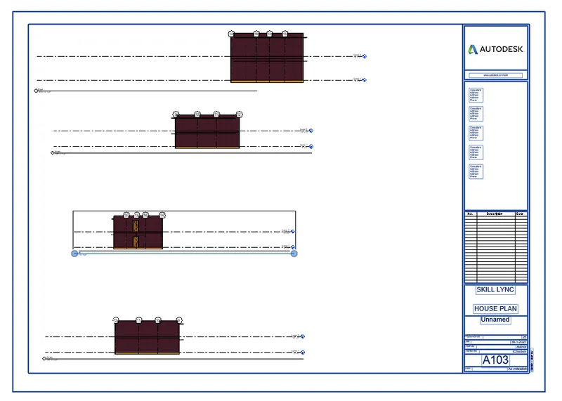
To create sheet templet and add diffrent views in it.
AIM10:-
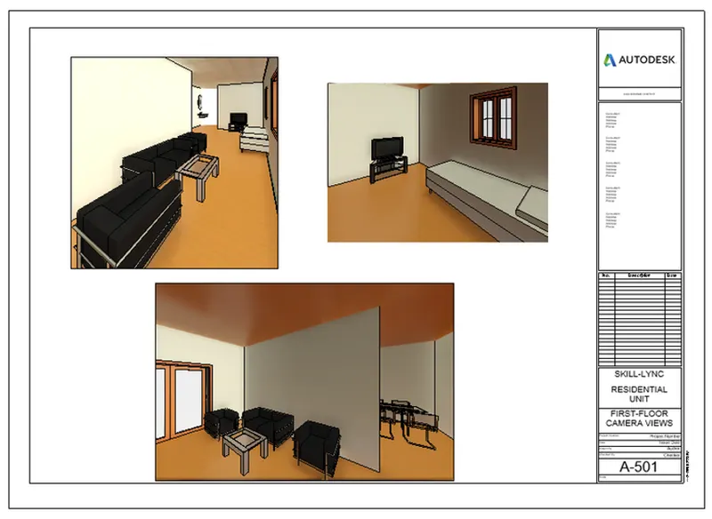
To crate a cemeraspecific view or 3D view of each room.
PROCEDURE :-
- Inorder to create a camera specific view, first go to view tab.
- Then choose 3D drop down and in that choose camera.