3D Creation of Ceiling, Roof, Architectural plan, Structural plan, Sectional view, Elevation view and Camera specific view for a house plan using REVIT
3D Creation of Celing, Roof, Architectural plan, Structural plan, Sectional view, Elevation view and Camera specific view for a house plan using Revit
Tools Used:
a. Ceiling
b. Sheet
c. Place a view
d. Levels
e. Grids
f. Roof
g. Place components
h. Load family
i. Property browser
j. Stair
k.Columns
l. Beams
m. Section
n. Elevation
- Double click on revit 2023 software which is alredy download from autodesk website.Open Rivet software
- From the model tab in recent file ,click on Challange 3.
1) Based on the project saved from Week 3, proceed from the First Floor Level. Model a Ceiling from the architecture tab above the walls at the first-floor level
Aim : To model a ceiling above the architectural plan created.
Procedure:
Step 1: Open the project created.
Step 2: Click on first floor in plan view
Step 3: Click on ceiling from the architectural tab.
Step 4: Click on sketch ceiling. draw the ceiling by using line
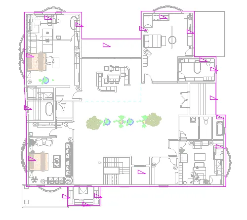
Step 5: Go to level 2 plan view and click on the rooms to create ceiling.
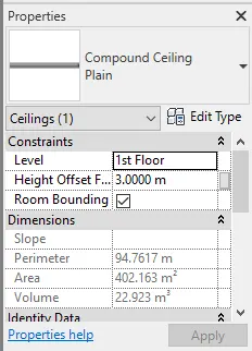
Step 6: Give the offset from level 2 as 400 the property browser. i.e. 3m from 1st floor base level.
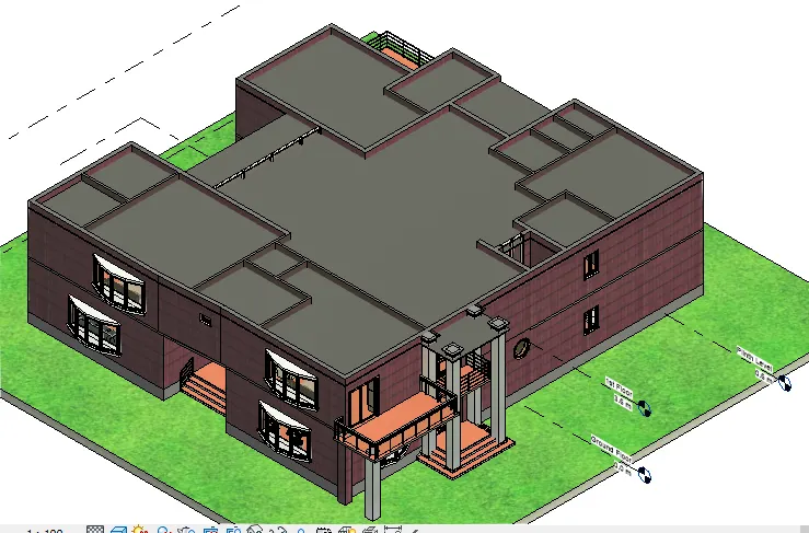
Result: Ceiling is modelled above the architectural plan.
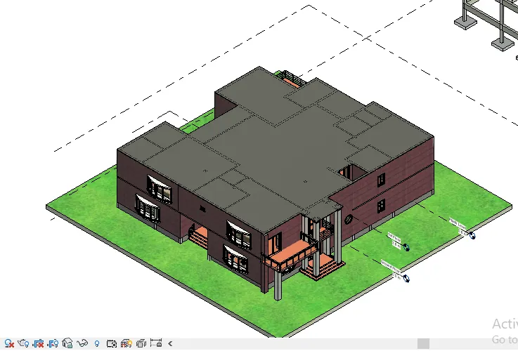
2) Model a roof above the ceiling by selecting the footprints of the ceiling. Using the adjustment toolbars appearing on-screen adjust the roof slope to 10 degrees
Aim : To create roof above the ceiling and adjusting the roof slope to 10 degree.
Procedure:
Step 1: Go to roof level floor plan
Step 2: Click on roof tab under architecture tab.
Step 3: Click on pick lines and with draw lines connect the roof line in level 3
Step 4: Give offset 0.25m and 1m. Trim unrequired lines.
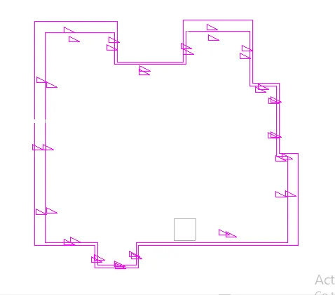
- Delete inner boundreis of roof.
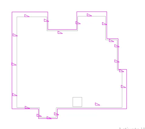
- Then press ok.
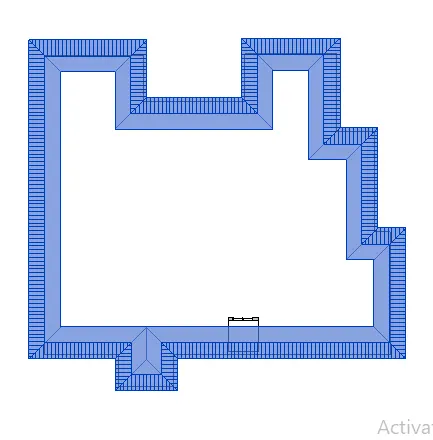
Step 5: Go to 3d view.
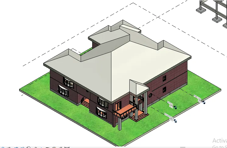
Step 6: Click on the roof in 3d view.
Step 7: We can drag the arrows provided to adust the slopes.
Step 8: In property browser dimension section , we can chnage the roof slope to 10 degree.
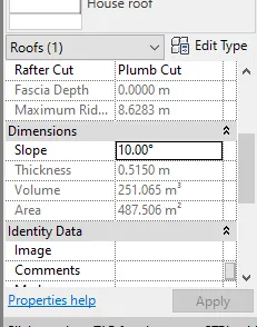
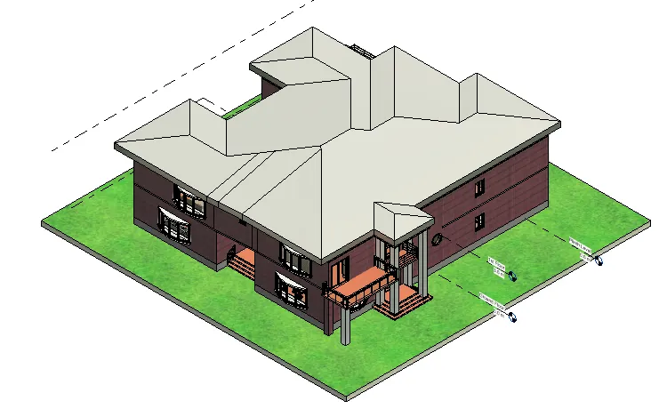
Step 9: Click on edit type Create duplicate and give name "Home roof".
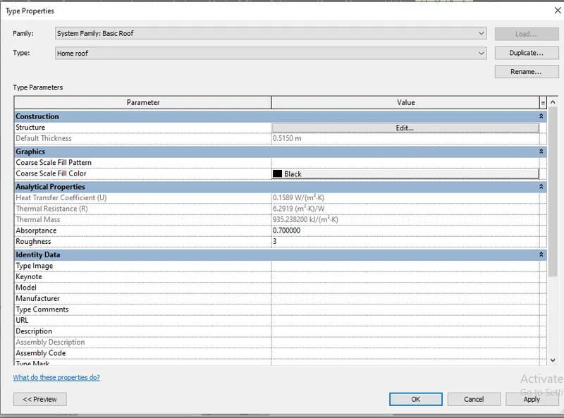
- then type properties dialogue box appears from structure edit.
- Change material from material browser and click ok
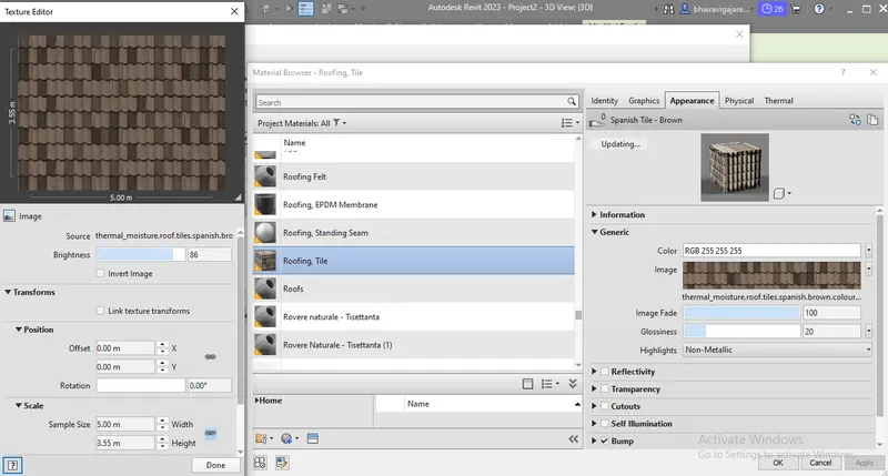
Result : Roof is created above the ceiling and slope is adjusted to 10 degree.
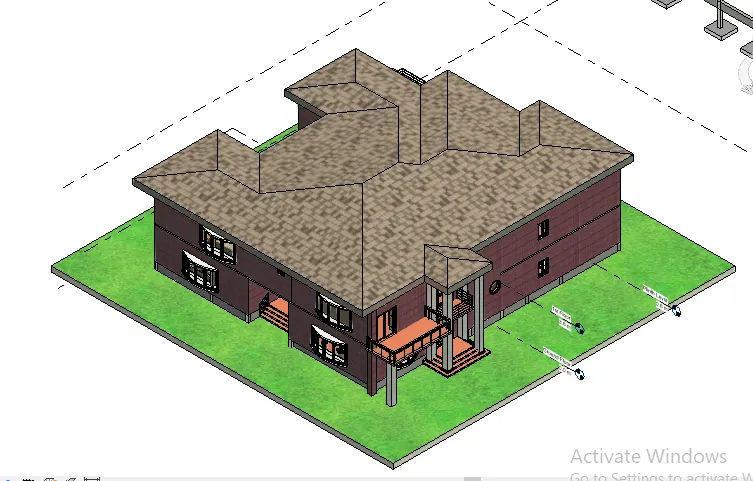
3) Using the file saved from weeks 2 to 4, create plan views for ground floor level and first-floor level including all the walls, floors, and components. Separate them to architecture and structural plans
a. Architecture plan must have walls, floors, and all the components placed within the building
Aim : To create plan views for ground floor and first floor levels and seperate them to architectural
Procedure:
a. Architectural plan - walls , floors and all components inside building.
Step 1: In architetcural tab click on walls and draw the walls.
Step 2: Click on doors and window tab under architectural, and place it wherever required.
Step 3: Click on floors and click on pick lines and clcik on the outline lines . Draw the floor where required by lines at plinth level which is floor of house. again draw floor by using rectangle in floor i.e ground of house.
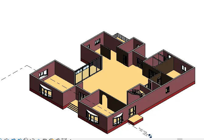
Ground floor
Step 4: Create room tags by clicking on room in architecture tab.
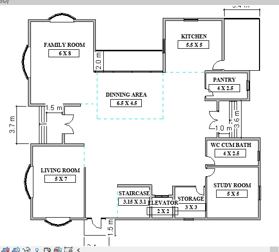
Step 4: Click on place a component under architectural tab and if the componets are present place it or click on load family.
Step 5: Load the components we need to place.
Step 6 : Click on load family to load the sofa ,couch table, Tv desk and shelf cabinet, Table, Lamp, inner plant in family room and living room
Step 7: Place dinning set in dinning area.
Step 8:load study table, drawing table, chair, light , Book shelf and place it in the room.
Step 9 : Place water closet ,bath tub and sink in the toilet
Step 10: Place full kitchen cabinets in kitchen. and Refrigerator is also loaded from the mid-range folder.
Step 11: Place storage shelf and storgae cabinet is loaded into the store room and pantry.
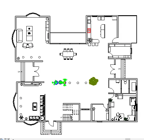
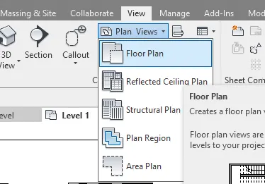
Step 12: For architectural plan Go to view tab select plan views then click on floor plan and choose ground level as a level 1
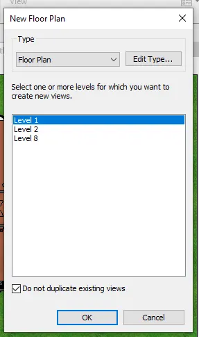
- Then press ok
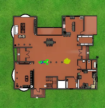
Ground floor
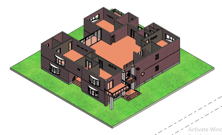
Step 13: Create first floor by using of copy and paste and aligning the plan to the other levels.
- Delete unwanted walls And then making changes which are required.
- create bedrooms by using partition wall having size is 0.12 m
First floor
Step 14: Create room tags by clicking on room in architecture tab.
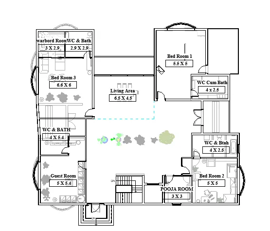
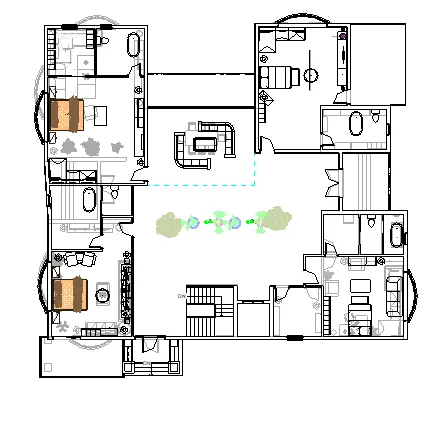
Step 15: Place bed, table ,chair, cabinets , sofa,tv desk in bedroom
Step 16: Place water closet ,bath tub and sink in the toilet.
Step 17: load sofa and table in living area.
Step 18: For architectural plan of first floor Go to view tab select plan views then click on floor plan and choose ground level as a level 2 similar to ground floor.
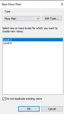
- Then press ok
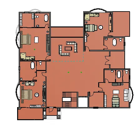
First floor
b. Structure plan must have details of only walls, floors, and columns
Aim : To create plan views for ground floor and first floor levels and seperate them to structural.
Procedure:
b. Structural plan: Columns and beams
Step 1: Create walls by clicking walls in architectural tab.
Step 2: Floor is created by clicking on floor tab and pick lines and select the lines.
Step 3: Place columns by clicking on column tab under architectural tab.
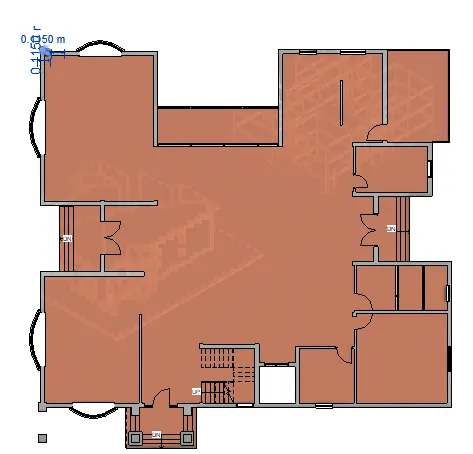
Step 4: Place columns by clicking on column tab under architectural tab.
Step 5: Click on architectural column and place the columns in all corners of the wall and also wherever required.
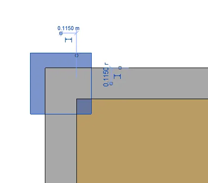
Step 6: As the column is bigger in size, go to edit type , dupilcate and change the size of column- 230x230mm.
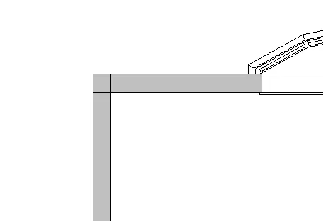
Step 7 : Similarly place the column in all the cornerns and wherever required.
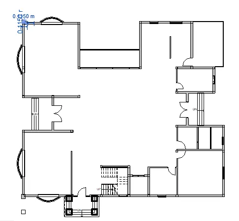
- Some coloum have top constraint is 1st floor and for remaning coloums are roof floor.
- the selected elements are the columns.
Step 8 : Delete the walls and floors.
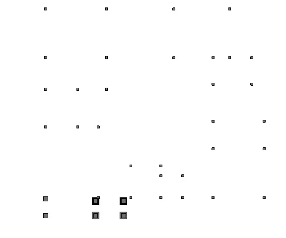
Step 9 : Select beam from structural tab , and draw beams connecting the column.
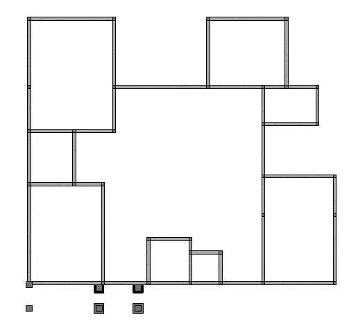
Step 10: then click 3d. which is show structural frmae of house.
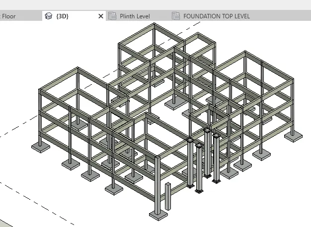
4) Using annotate toolbar add dimensions to all the walls and floors with reference to the longitudinal and transverse grids created in the project file
a. The architecture plan dimensions include details on where the components are placed within the buildings with relation to grids. Overall dimensions are sufficient for architecture plans
b. The Structure plan dimensions must include details on the position of all the walls and interior walls with reference to grids. Locate all the framing components of the building with reference to a fixed point using Structural plans
Aim : To add dimension using annotate toolbar to the architetcural and structural plan .
Procedure:
a. Architectural plan - dimensions with respect to the grids
Step 1: The grids are created along walls.
Step 2: Click on annotate tab, select linear dimension.
Step 3: Click on the two walls, to get the distance of the rooms.
Step 4: Again click on annotate , linear and select the grid points and the components .
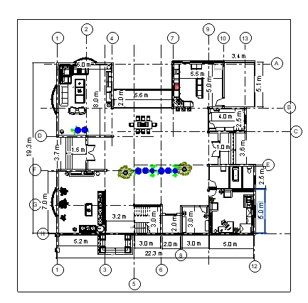
Ground floor
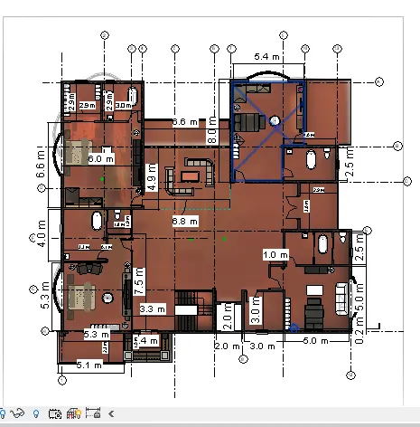
First Floor
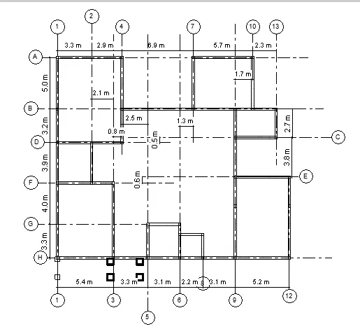
b. Structural - dimensions with respect to the grids
Step 1: Create columns on all corners of wall .
Step 2: Create beams connecting the columns.
Step 3 : Using grid tab , place the grids at the centre of the column.
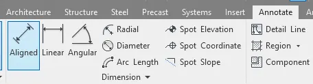
Step 4: Use annotate tab , aligned and linear to measure the dimension between the grids, grids and wall.
Step 5 : Measure the dimension from grid to grid.
5) Create a sheet template from the view tab and adjust the parameters on the sheet to add appropriate views
Aim : To create sheet template from the view tab and adjusting the parameters to add views.
Procedure:
Step 1: Click on view tab, select sheet option,
Step 2: If we need more sheet click on load button select title blocks and select the sheet we need.
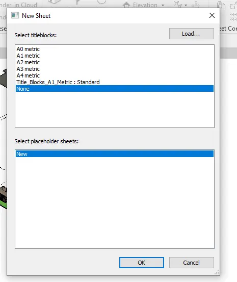
Step 3: select A1 metric . A sheet will be created
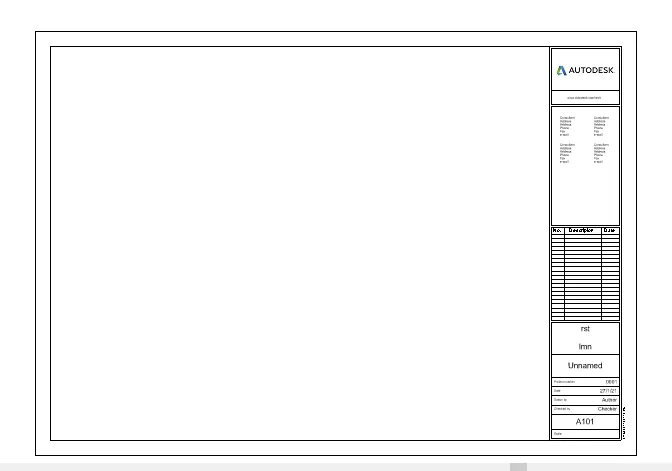
Step 4: We can edit the template by double clicking the letters.
Step 5 : To add views, click on place views under view tab.
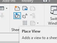
Step 6 : Select the views created to place it in the sheet. Click on add view to sheet.
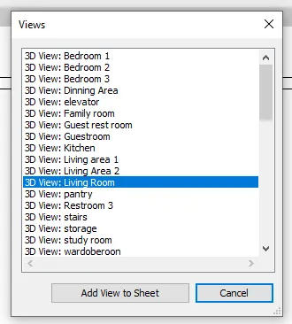
Step 7: When adding if the size is large , click on size crop, select scale and give a value( here 500) and apply.
Step 8: Click on Living room view and add it.
Step 9: Go to size crop for change size of view.
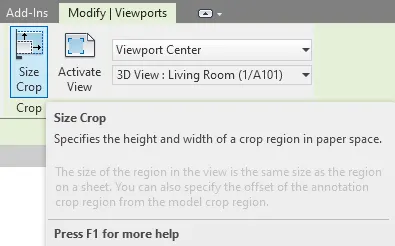
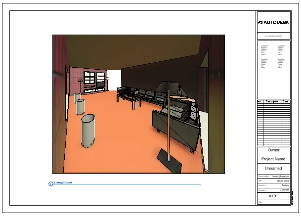
Step 10: Go to manage tab ,click on project information tab, The project information dialogue box appears ,enter the organisation name, project details etc
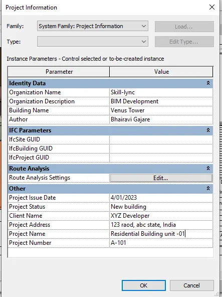
-Press ok. Where required to double click and information
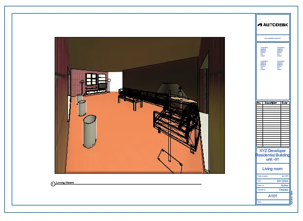
Step 9: Similarly create other sheet slesct A3
- Click on 3d view of Dinning area and 3d view of full building. and place in the sheet.
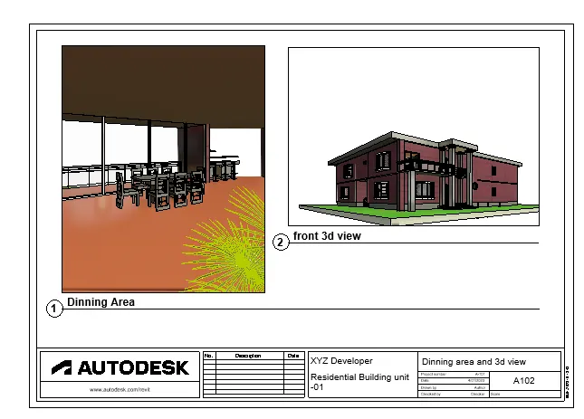
Result:
Sheet template is created and views are placed in the sheet template.
6) Using the elevation tab create the elevation views, looking at your building from East, North, South, and West
Aim : Creating elevations views using elevation tab from North , South, East and West.
Procedure:
Step 1: In view tab , click on elevation in plinth level view.
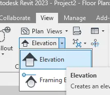
Step 2: Place the view where we need, elevation 1 will be created in the property browser.
Step 3: Click on elevation 1 to see the view.
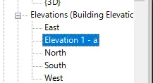
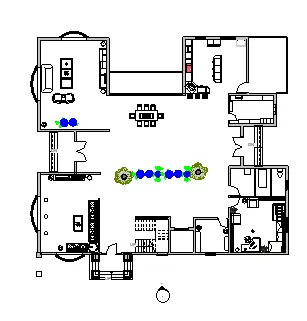
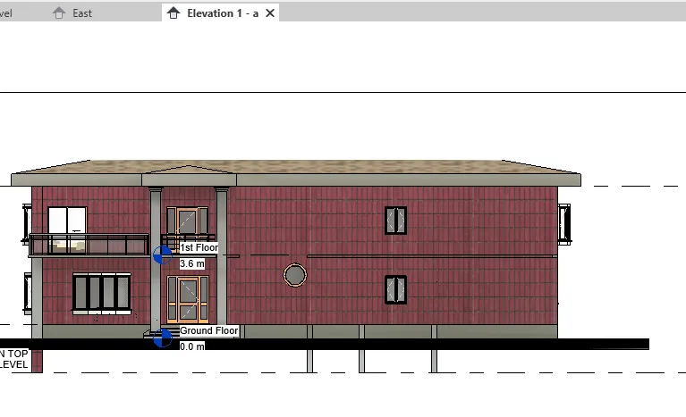
Step 4: Similarly place the elevation blocks in North, South, East and West and rename it espectively.
Step 5: Click on elevation tab from the project browser.
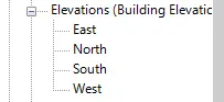
Step 6: Expand the elevation tab , we can see different elevations of North , East , West and South.
Step 7: Click on East view.
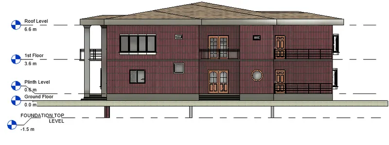
Step 8: Click on North view.
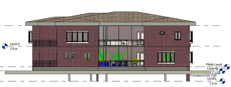
Step 9: Click on South view.
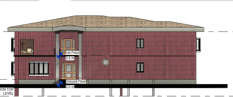
Step 10 : Click on West view.
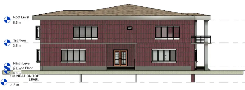
Step11 : To create more views, click on view -elevation and place the elevation blocks to where we need the view.
Result : North , South , East and West elevations are created using elevation tab.
7) Produce section cut through each room either cutting across longitudinally or in a transverse direction
Aim : To create section through each room creating sections longitudinally and transversely.
Procedure:
Step 1: Click on section tab from view tab , draw the section through the longitudinally and in a transverse direction.
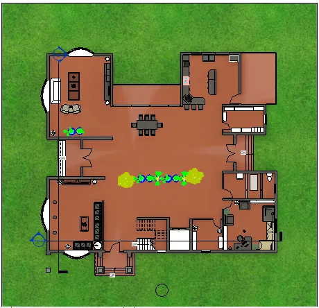
Step 2: Click on section tab from view tab , draw the section through the family and living transverse direction.
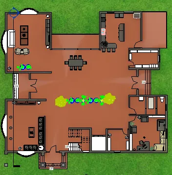
Step 3: Go to property browser and rename it then Click on section view from the property browser , we can see the view.
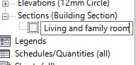
- Click on this view for see this view.

Step 4: Click on section tab , from view tab and place the section through the dinning longitudinally.
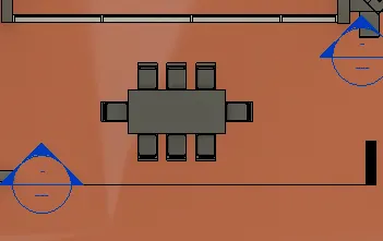
Step 5: Click on section view and select the created section from property browser, we can change the name by right clicking and rename it to Dinning
area.
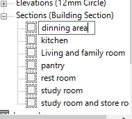
Step 6: Click on the bedroom view from the section tab.
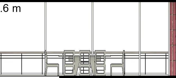
Step 6: Click on section from the view tab . and draw the section Logitudinaly in the restroom.
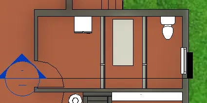
Step 7: Click on section tab from property browser and rename the section to restroom
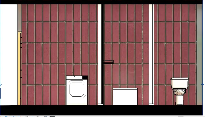
Step 8: Click on section view from view tab, and draw section line through Logitudinaly direction in kitchen and pantry.
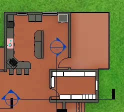
Step 9: Click on section from the property browser and rename it to kitchen and pantry then select the view.
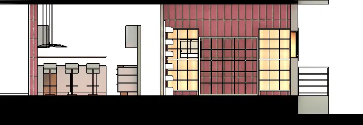
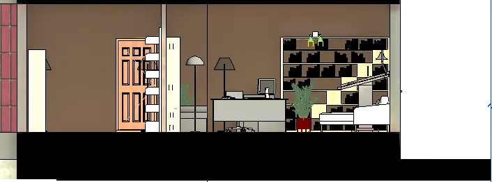
Step 10: Click on section view from view tab, and draw section line through Logitudinaly direction in study room and store room.
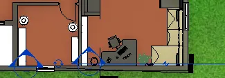
Step 11 : Click on section from the property browser and rename it to studyroom and store room afater that select the view.
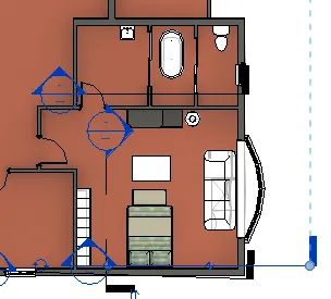
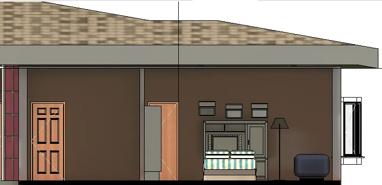
Step 10: Create a longitudinalsection for the Bedroom 1,2, and transverse section for bed room 3 and guest room.
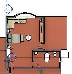
Bedroom 1,2
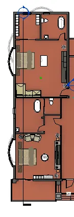
bed room 3 and guest room.
Step 11: Select the view from section under property tab.
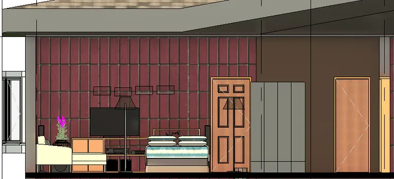
Bedroom 1,2
bed room 3 and guest room.
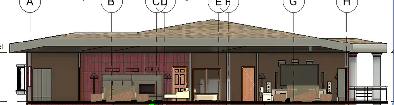
Step 12:Create a longitudinal section for the living area.
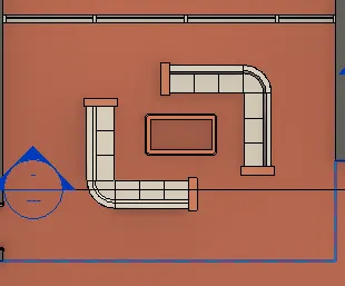
Step 13: Select the view from section under property tab.
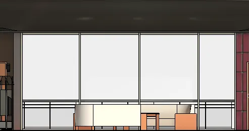
Result:
Section view are created for:
a. Living and family room
b. Bedroom 1,2,3 and guest room
c. Restroom
d. Kitchen
e. Store room and pantry
f. study room
g. living and dinning area.
8) Classify the views, Plan Views, Section Views, and Elevation views to either Design or Documentation category using Properties browser
Aim : To classify different views like plan views, section views and elevation views and docment it in project browser
Procedure:
Step 1: In the property browser we can see all the views are visible.
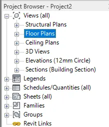
Step 2: Click on each of the tab to expand it , so that we can see the plans, elevations and section view created.
Step3: For plan view , click on the floor plans and expand it.
Step 4: We can see that Ground floor, plinth level, 1st floor and roof level which are created are visible.
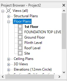
Step 5: Select on each level to see the floorplan of that level. - 1st floor created at 3600mm and Roof level at 6600mm.
Step 6: Select First floor so that we can see the plan view of first floor level.
Step 7: Click on elevation in property browser , expand it and we can see that different elevations views are there.
Step 8: Click on East view.
Step 9: Click on North view.
Step 10: Click on South view.
Step 11 : Click on West view.
Step 12: Click on section , to expand the views.
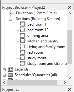
Step 13: Select Living and family view.
Step 14: Select restroom view.
Step 15: Select dinning view.
Step 16: Select kitchen and pantry view.
Step 17: Select study and store room view.
Step 18: Select Bedroom 1,2,3,and guest room view.
Bedroom 1,2
bed room 3 and guest room.
Step 19: Select Living area view.
9) Using the sheet template produced create multiple sheets as follows
a. A 101- Ground Floor Architecture Plan
b. A 102- First Floor Architecture Plan
c. A 103- Roof Plan
d. S 101- Ground Floor Structural Plan
e. S 102- First Floor Structural Plan
f. S 103- Roof Framing Plan
g. A-201- North-South Elevations
h. A-202- East-West Elevations
Add additional sheets based on the sections created in your Revit file
Aim : Creating multiple sheets using sheet template
a. A101- Ground Floor Architectural Plan
b. A102 - First Floor Architectural Plan
c. A103- Roof Plan
d. S101- Ground Floor Structural Plan
e. S102- First Floor Structural plan
f. S103- Roofframing Plan
g. A201- North -South elevations
h. A202- East West elevations
i. A301-A307 Sections
Note - Each sheet view scale is 1:50
Procedure:
a. A101 - Ground floor architectural plan
Step 1: Click on create sheet from the view tab .
Step 2: Select the sheet , or load another sheets ( if needed.) from load go to title box select template which you want. then click
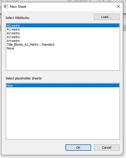
Step 3 : Select A0 Matric sheet.
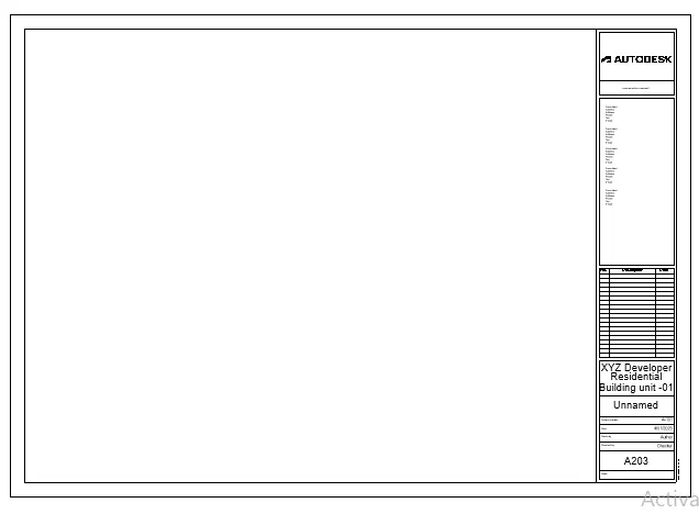
Step 4: The sheet created will be visible in the project browser , rename either sheet name as A101- Ground floor architectural plan
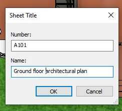
Step 5: Click on place view in the view tab , a dilaogue box appears.
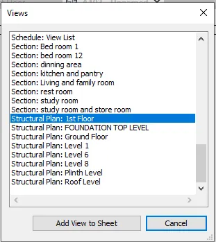
Step 6: Select ground floor plan at level 1 , click on add view to sheet. change its scale from properties.
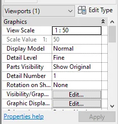
- Then move by curosr set it appropriate.
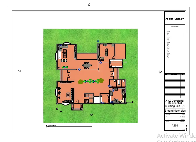
b. A102- First Floor architectural plan
Step 7 : Create another sheet from view tab - new sheet.
Step 8 : Go to project browser in section of sheets select it by right click then Rename it to A 102- First floor architectural plan
Step 9 : Click on place view under view tab
Step 10: Select first floor plan at level 2, add view to sheet. Then change its scale from properties.
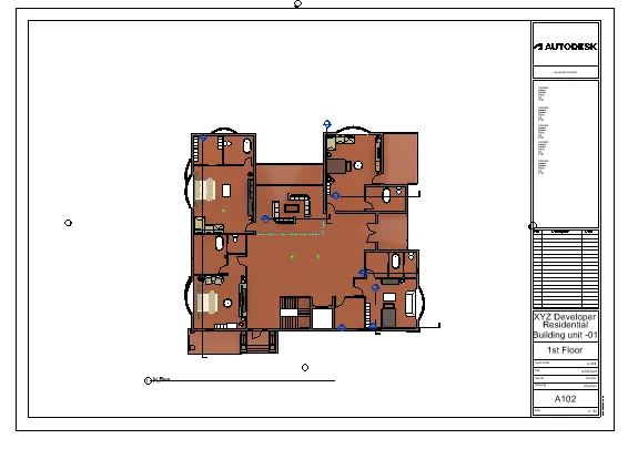
c. A103- Roof plan
Step 11: Click on create sheet from the view tab.
Step 12: Rename the sheet name to A103-Roof floor plan
Step 13: Select place view and place ceiling plan.
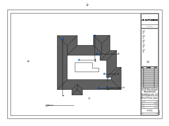
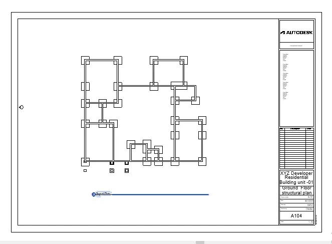
d. S101- Ground Floor Structural Plan
Step 13: Select sheet from view tab
Step 14: Rename it to S101- Ground Floor structural plan.
Step 15 : Click on place view from the view tab , and place the structural plan.
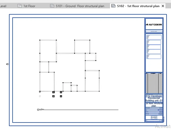
e. S102- First floor structural Plan
Step 16: Select the created column and change the top constrain to level 3 with base constrain as level 1.
Step 17: Select sheet from the view tab.
Step 18: Rename it to S102- First floor strcutural plan.
Step 19: Click on place a view from view tab.
Step 20: Place the view in the sheet and adjust the scale if needed , here 1:50 scale is used.
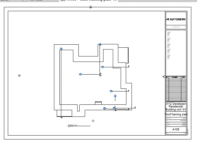
f. S103- Roof Framing Plan
Step 21: Create sheet from the view tab.
Step 22: Rename the sheet number and name to Roof Framing Plan.
Step 23: Click on place view and place the roof plan in the sheet
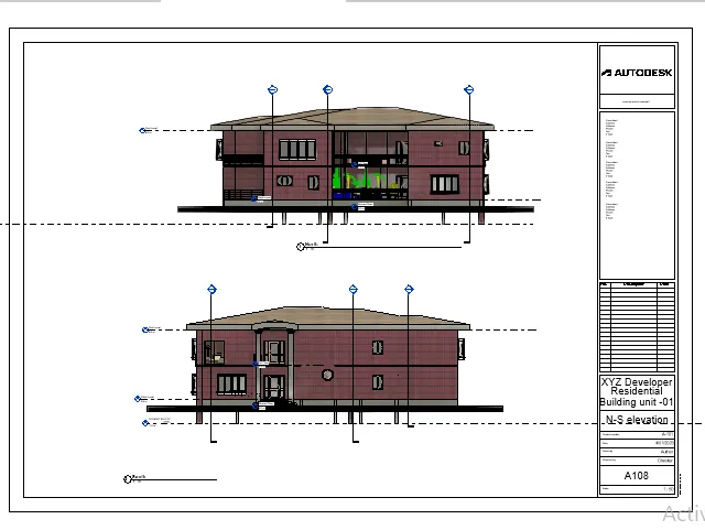
g. A201- North-South elevations
Step 24: To create elevations, in view tab click on elevations and place the elevation in between North and South and rename the created elevation as North- South.
Step 25: Click on sheets from the view tab.
Step 26: Rename the number and sheet name to A201- North- South elevations.
Step 27 : Click on place view and place elevation North -South.
Step 28: Click on the viewport window and level (in elevation view only) and right click and hide element to hide the window and level in sheet.
Step 29 : To unhide click on reveal hidden elements in the bottom tab, then click on the hided element displayed , then right click and there will be an option to unhide elements, click on reveal again to exit from it.
Step 30: Place the image in the centre.
h. A202- East -West elevations
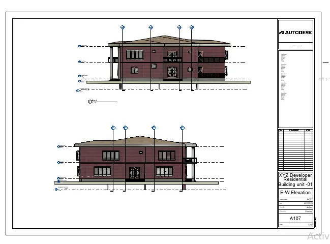
Step 31: Create elevation from the view tab - elevation and place the elevation between East and West.
Step 32: Expand the elevation tab and rename the name to East -West elevation.
Step 33: Create sheet from the view tab - sheet and renameit toA202- East West elevation.
Step 34 : Click on place view and seelct the east- west elevation created.
Step 35 : Adjust the view and scale it accordingly.
i. Sections:
Step 36: Create section by clicking section tab for each rooms.
Step 37: As the sections are already created , craete sheets i.e. A3 matric and place them in each sheet.
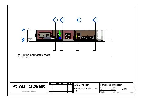
Step 38 : Click on sheet from the view tab, and rename it as A 301- Section -living and family room.
Step 39: Click on place view and place the section view created.
Step 40: Create sheet for dinning section from view tab A302- Rest room and kitchen and pantry section.
Step 41: Place the section views - .Rest room and kitchen with pantry
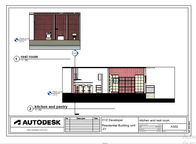
Step 42: Create sheet from view tab and rename it to A303- dinning and living area Section
Step 43 : Click on place view and place the section of dinning and living area and adjust the scale.
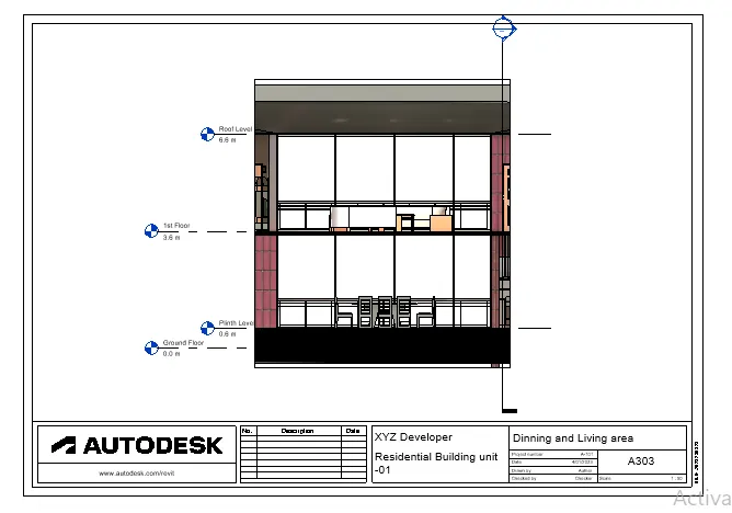
Step 44: Create sheet from view tab and rename it to A304- Study room and store room Section
Step 45: Click on place view and place the section of Study room and store room and adjust the scale.
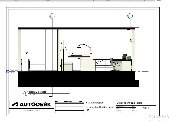
Step 46: Similarly create sheet for Bedroom1,2 A305-Bedroom1,2 section
Step 47: Click on place a view and place the section view of Bedrooms.
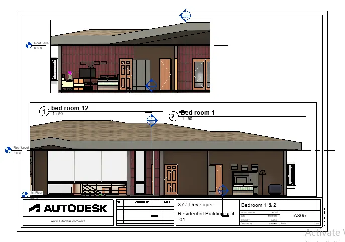
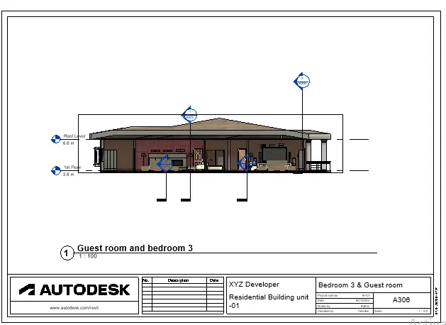
Step 48: Again create sheet for Bedroom1,2 A306-Bedroom3 and guest room section
Step 49: Click on place a view and place the section view of Bedroom3 and guest room .
Result:
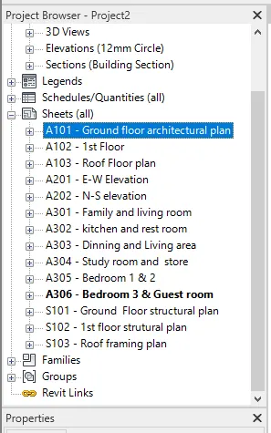
Respective sheets are created using sheet template
a. A101- Ground Floor Architectural Plan
b. A102 - First Floor Architectural Plan
c. A103- Roof Plan
d. S101- Ground Floor Structural Plan
e. S102- First Fllor Structural plan
f. S103- Roofframing Plan
g. A201- North -South elevations
h. A202- East West elevations
i. A301-A306 Sections
10) Create a camera-specific view or a 3D view in each room ( living, dining, bedroom). Based on the views create a new set of sheets starting A-501 (you can add as many sheets after, 502, 503.. n)to place the 3D view images. Produce the sheets as a part of project drafting.
Aim : Creating camera views for each rooms and creating sheets for each of the 3d view.
Procedure:
Creating views and sheets :
Step 1: Go to floor plan , from the view option-3d view- click on camera , and place the camera in which room we need the view.
Step 2: Created views will be seen under 3d in property browser. Then create sheets.
- Living Room:
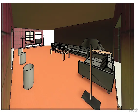
Step 3: Place the camera in the living room, in the floor plan.
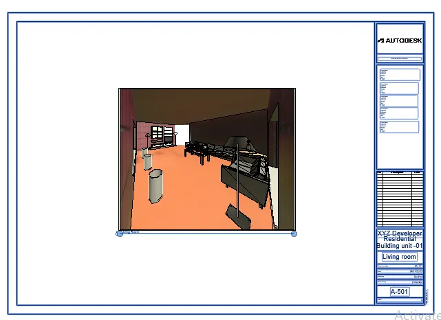
Step 4: Click on the 3d view created from the property browser and rename it to living room
Step 5 : To create sheet , go to view tab click on sheet , seelct the sheet we need or load more and seelct the required.
Step 6: Rename the sheet name as A501 - Living room
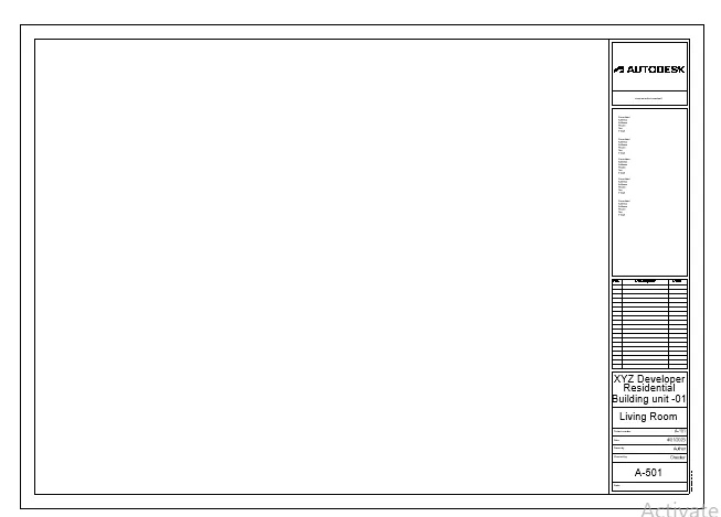
Step7 : Click on place view and click on the living from the dialogue box.
- Family Room:
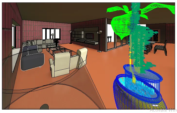
Step 5: Place the camera in the family room, in the floor plan.
Step 6: Click on the 3d view created from the property browser and rename it to Family room
Step 5 : To create sheet , go to view tab click on sheet , seelct the sheet we need or load more and seelct the required.
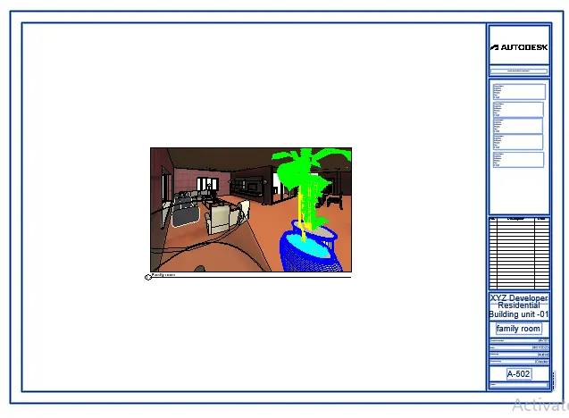
Step 6: Rename the sheet name as A502 - Family room
Step7 : Click on place view and click on the Family room from the dialogue box.
- Dinning area:
Step 8: Click on camera from view tab under 3d view.
Step 9: Place the camera such that the dinning view is visible.
Step 10: Expand the 3d view from the property browser and rename it to dinning.
Step 111: Click on the dinning view.
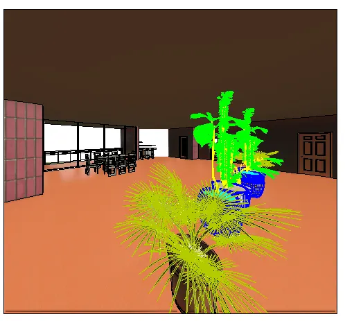
Step 12: Create another sheet from the view tab, rename it to A503 - Dinning room.
Step 13: Click on place a view , and select the dinning area.
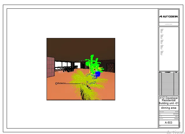
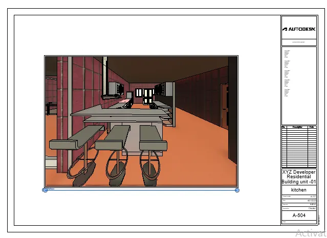
- Kitchen :
Step 14: Click on camera from view tab under 3d view.
Step 15: Place the camera such that the kitchen view is visible.
Step 16: Expand the 3d view from the property browser and rename it to kitchen.
Step 17: Click on the kitchen view.
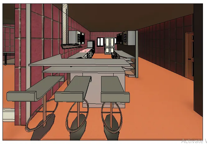
Step 18: Create again sheet from view tab, and rename it to A504- Kitchen.
Step 19: Click on place a view and place the kitchen view.
- Study room
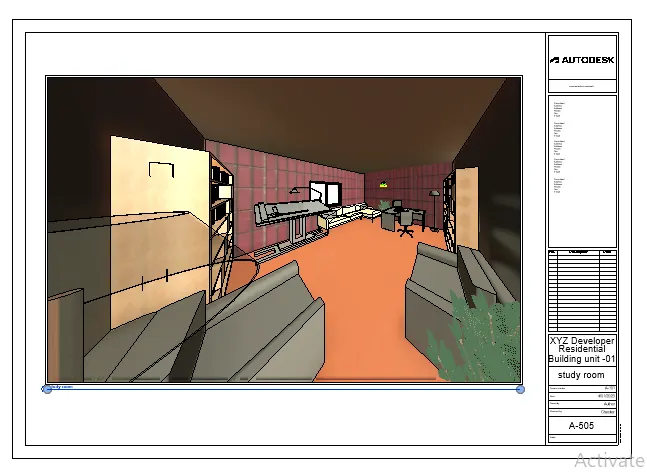
Step 20: Click on camera from view tab under 3d view.
Step 21 : Place the camera such that the studyroom view is visible.
Step 22: Expand the 3d view from the property browser and rename it to study room.
Step 23: Click on the study view.

Step 24: Create another sheet from view tab, and rename it to A505- study room.
Step 25: Click on place a view and place the studyroom view.
- Restroom:
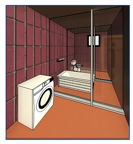
Step 19: Click on camera from view tab under 3d view.
Step 20: Place the camera such that the restroom view is visible.
Step 21: Expand the 3d view from the property browser and rename it to restroom.
Step 22: Click on the restroom view.
- Store room and pantry:
Step 23: Click on camera from view tab under 3d view.
Step 24 : Place the camera such that the store and pantry view is visible.
Step 25 : Expand the 3d view from the property browser and rename it to store, pantry.
Step 26: Click on the store and pantry view.
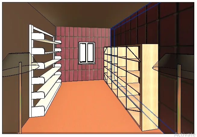
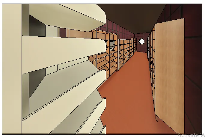
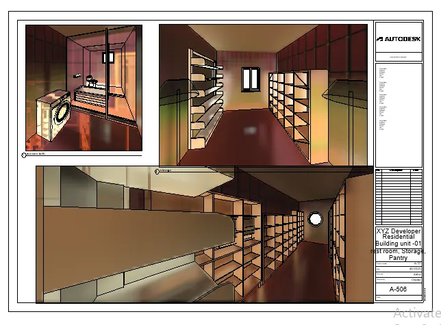
Step 27: Create new sheet from view tab, and rename it as A506- Rest room,pantry and store room.
Step 28: Click on place view and place the Rest room,pantry and store room. view.
- Bedrooms 1 and 2:
Step 29: Click on camera from view tab under 3d view.
Step 30: Place the camera such that bedrooms view is visible.
Step 31: Expand the 3d view from the property browser and rename it to bedroom 1 and 2 .
Step 32: Click on the bedroom 1 and 2 view.

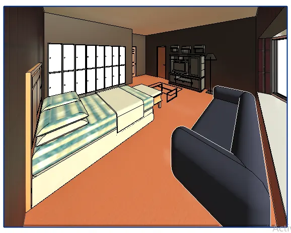
Step 33: Create another sheet from view tab, and rename it to A507- Bedroom1 and 2.
Step 34: Click on place a view and place the bedroom view.
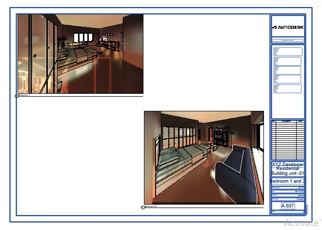
- Bedrooms 3
Step 35: Click on camera from view tab under 3d view.
Step 36: Place the camera such that bedroom 3 view is visible.
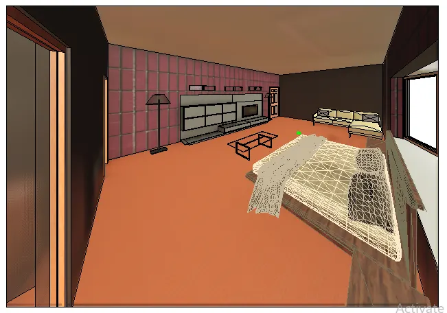
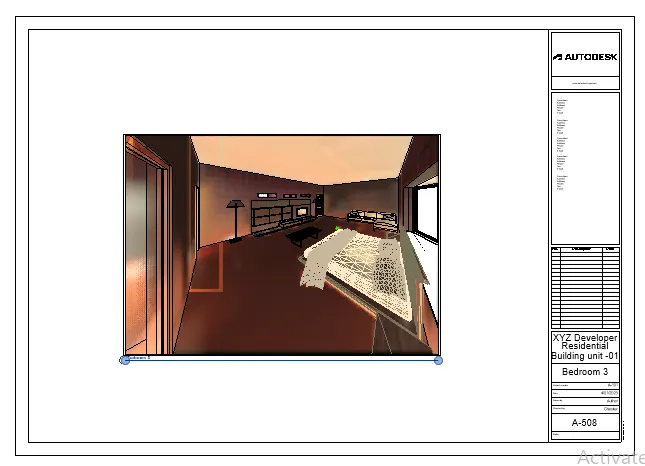
Step 37: Expand the 3d view from the property browser and rename it to Bedroom 3.
Step 38: Click on the bedroom 3 view.
Step 39: Create new sheet from view tab, and rename it as A508-Bedroom3.
Step 40: Click on place view and place the Bedroom3 view.
- Guest room:
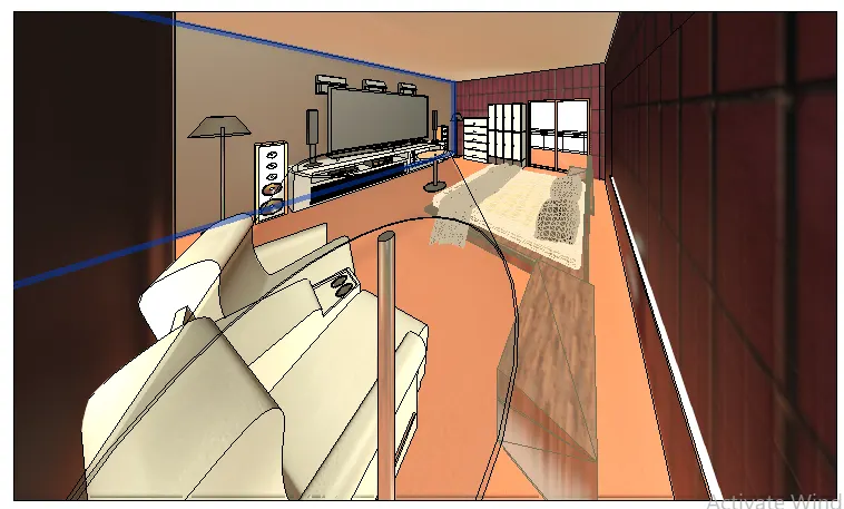
Step 41: Click on camera from view tab under 3d view.
Step 42: Place the camera such that guestroom view is visible.
Step 43: Expand the 3d view from the property browser and rename it to guest room.
Step 44: Click on the bedroom 3 and guest room view.
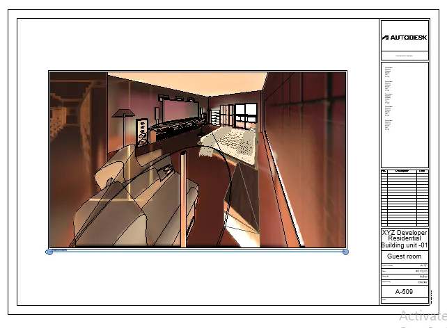
Step 45: Create new sheet from view tab, and rename it as A509- Guest room.
Step 46: Click on place view and place the Guest room view.
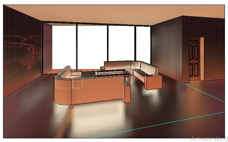
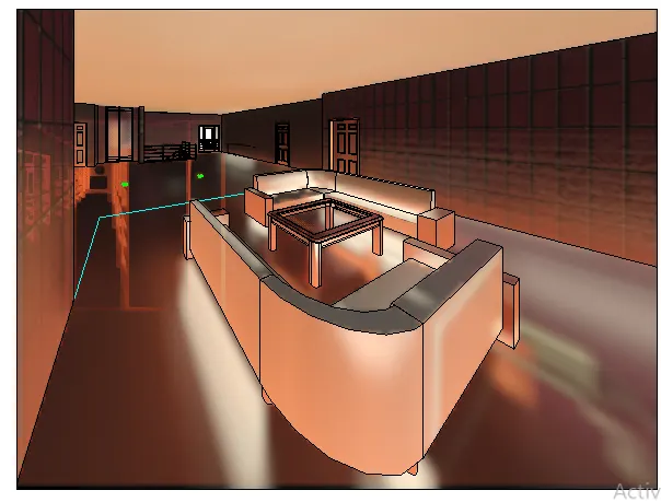
- Living Area:
Step 47: Click on camera from view tab under 3d view.
Step 48: Place the camera such that living area view is visible.
Step 49: Expand the 3d view from the property browser and rename it to living area.
Step 50: Click on the living area view
.
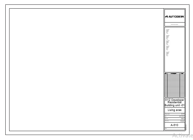
Step 51: Create again sheet from view tab, and rename it to A510- living area.
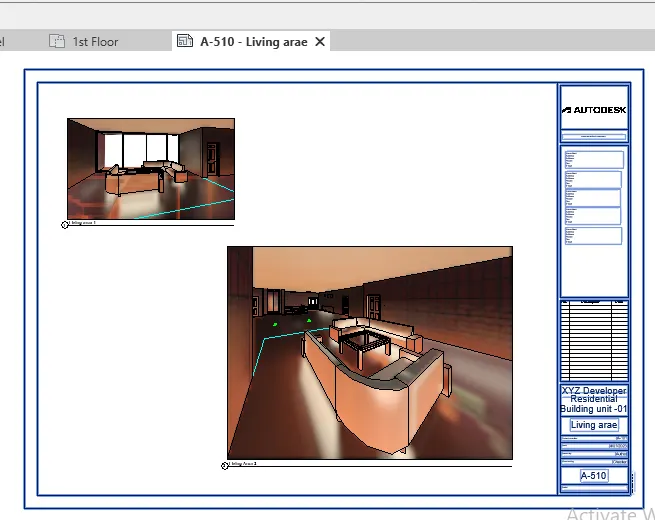
Step 52: Click on place a view and place the living area view.
Result:
Camera views of all rooms are created and sheets are created accordngly.
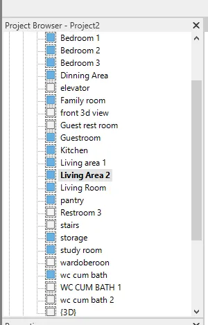
Views:
Living room and area
family room
Dinning area
Bedroom1,2 & 3
Rest room i.e. wc cum bath
Kitchen
Store and pantry
Study room
Guest room
Sheets:
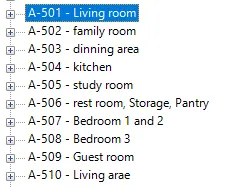
A501- Living room
A502- family Room
A503- Dinning area
A504- Kitchen
A505- study room
A506- Storage, rest room, pantry
A507 - Bedroom 1 & 2
A508 - Bedroom 3
A509 - Guest room
A510 - Living area