3D Creation of Ceiling, Roof, Architectural plan, Structural plan, Sectional view, Elevation view and Camera specific view for a house plan using REVIT
1.
AIM:
To model a ceiling from the architecture tab above the walls at the first floor level
INDRODUCTION:
- The creation of ceiling within Revit is a very similar process to that of floors and Roofs
- Place a correct ceiling plan view before you start
PROCEDURE:
STEP 1
- First open the Revit software and select the ceiling option from the architecture tool bar
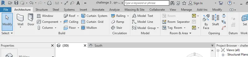
STEP 2
- After selecting ceiling option select the room one by one
- The ceiling will be created
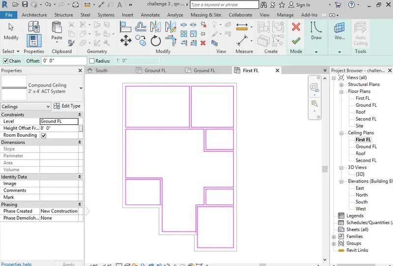
- Create ceiling using the line tool
- After that finish the model
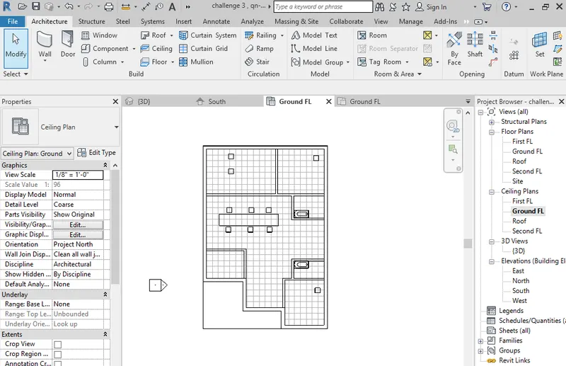
- Ceiling is created in the ground floor
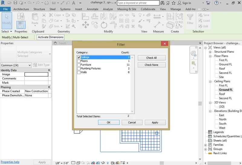
- Copying the ground floor ceiling to the first floor by filter option
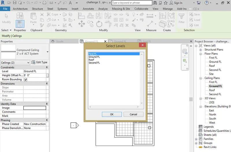
- Paste it in the first floor
STEP 3
- First floor ceiling has been done
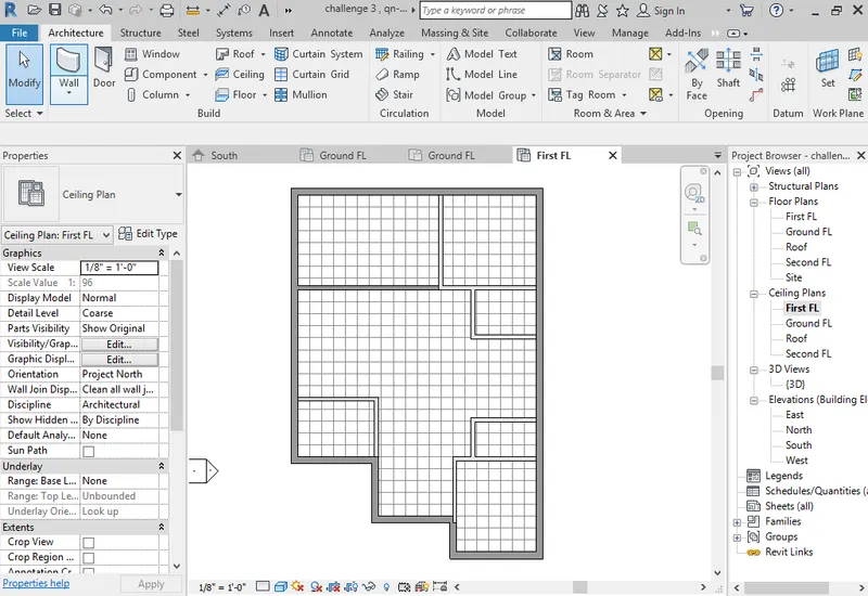
- The 3D view of first floor celing
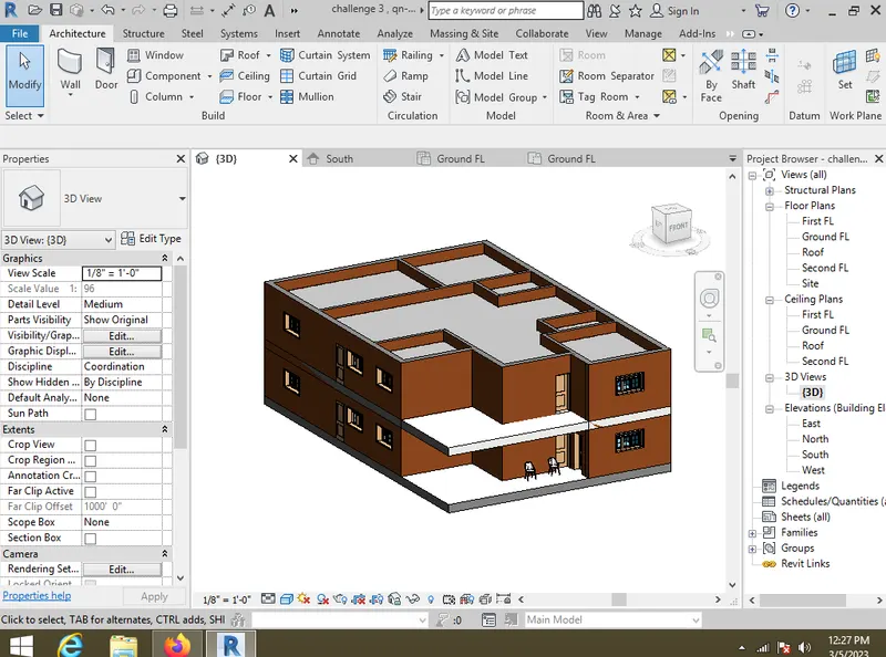
Result:
The ceiling has been done succesfully from the architecture tab above the walls at the first floor level
2.
AIM:
To model a roof above the ceiling by selecting the footprints of the ceiling.
INDRODUCTION:
- Roof, covering of the top of a building , serving to protect against rain, snow, sunlight wind and extremes of temperature
- Roofs have been constructed in a wide variety of forms flat, pitched, vaulted, domed, or in combinations as dictated by the technical, economic
PROCEDURE:
STEP 1
- Open architecture tool bar , select roof by footprint option
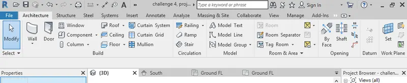
STEP 2
- Select roof by foot print option.
- They asked to which the level roof should be, click on that level
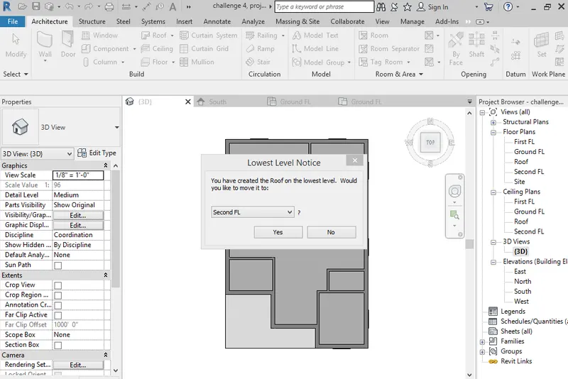
- By using line tool draw a boundary line through out the model
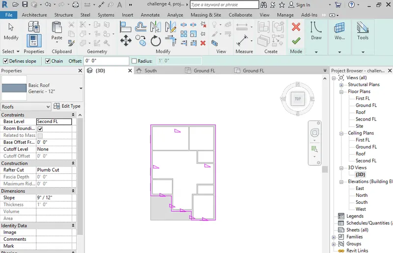
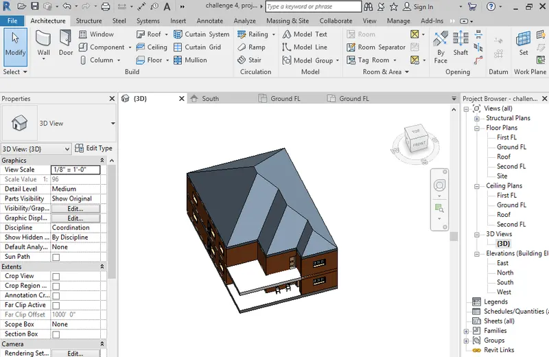
- Then finish the model
- Adjust the roof slope to be 10 degree
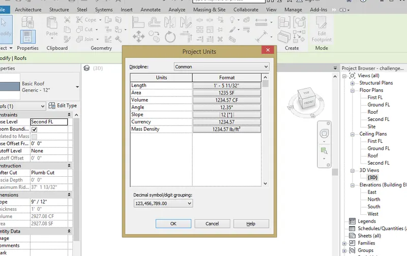
- Click ok and change the slope value in properties
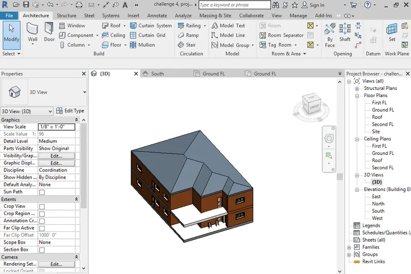
- The roof has been created.
RESULT:
The roof has been created succesfully
3.
AIM:
To create plan views for ground floor level and first floor level including all the walls, floors, and components and to separate them to architecuture and structural plans
INTRODUCTION:
- The structural plan view is the default view when you start a new project suing structural template
- Floor plan view is the default view in a new architectural projects
PROCEDURE:
STEP 1
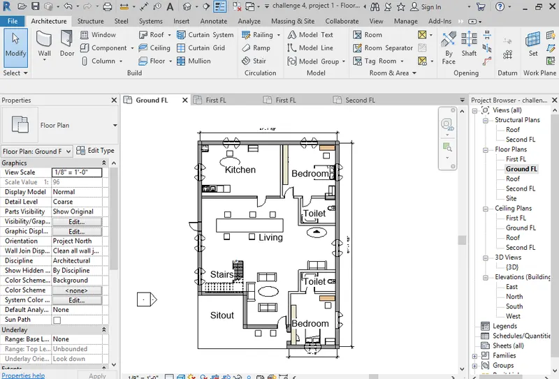
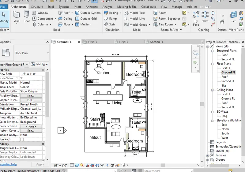
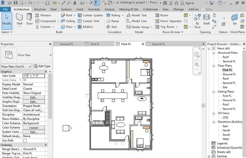
- Architectural plan of ground floor
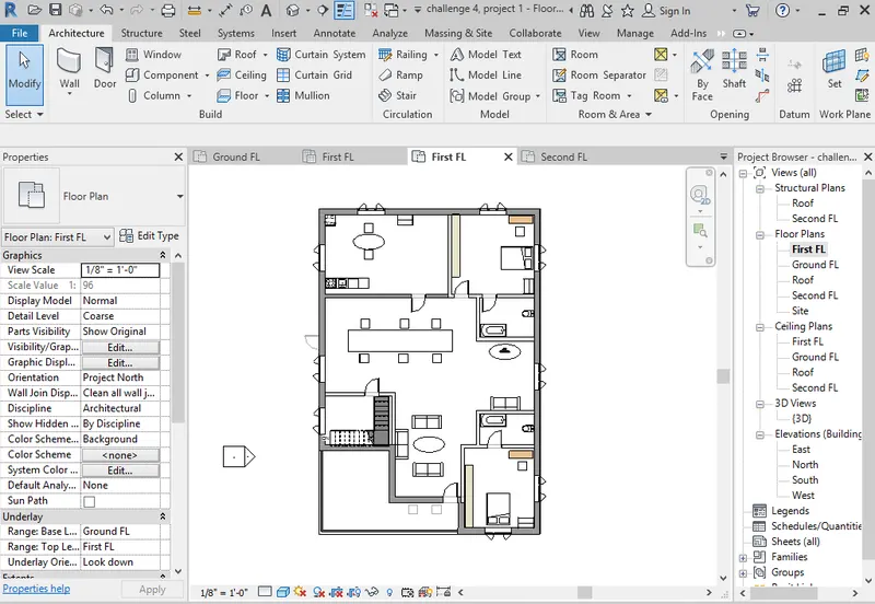
- Architectural plan of First floor
STEP 2
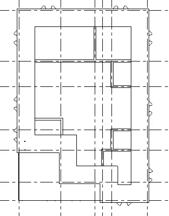
- Structural plan of ground floor
- Structural plan of first floor
RESULT
- Succesfully complated the plan views for ground floor level and first floor level including all the walls, floors, and components and to separate them to architecuture and structural plans
4.
AIM:
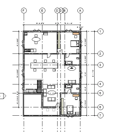
To add dimensions to all the walls and floors with reference to the longitudinal and transvere grids created in the project file
INTRODUCTION:
- The structural plan view is the default view when you start a new project suing structural template
- Floor plan view is the default view in a new architectural projects
PROCEDURE:
STEP 1
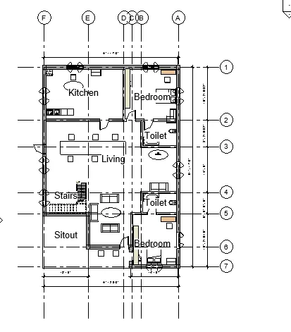
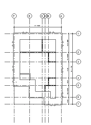
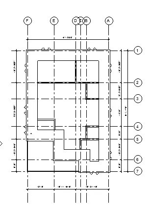
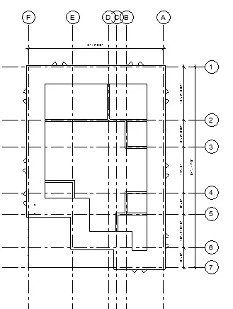
- Draw the longitudinal and tranverse grids to the architectural floor plan and add dimension to it.
STEP 2
- Draw the longitudinal and tranverse grids to the structural floor plan and add dimension to it.
RESULT
- Succesfully completed longitudinal and transverse grids and dimensions are to structural and architectural floor plan
5.
AIM:
To create a sheet template from the view tab and adjust the parameters on the sheet to add appropriate views
INDRODUCTION:
- Create views on a project template
- When creating a project template, you can include sheets in the template
- Leave the view empty but assign standard names to them.
PROCEDURE:
STEP 1
- First click on the sheet option from the view tool bar
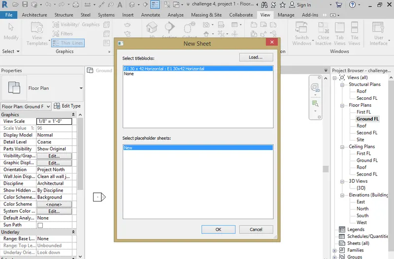
- After clicking the sheet new tab will be visible
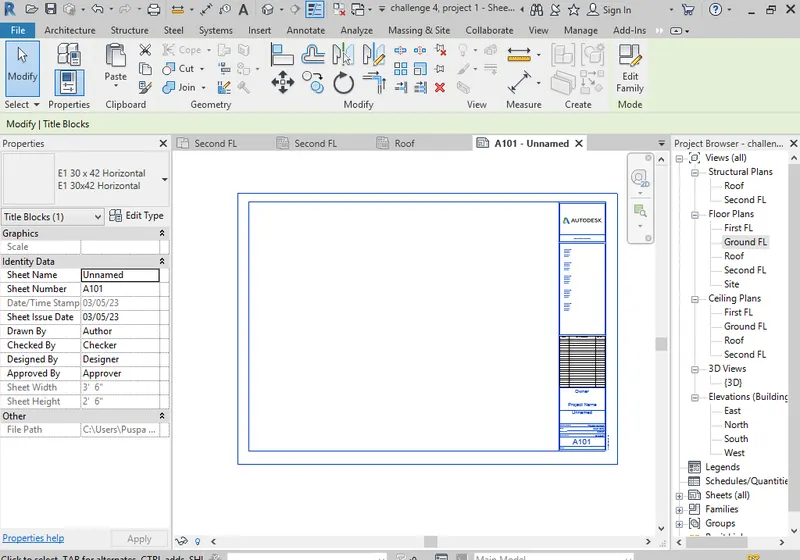
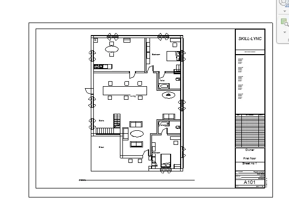
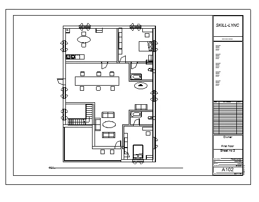
- Edit the sheet number, project name and add first floor and ground floor separately
RESULT
- Successfully completed the sheet template from the view tab and adjust the parameters on the sheet to add appropriate views
6.
AIM:
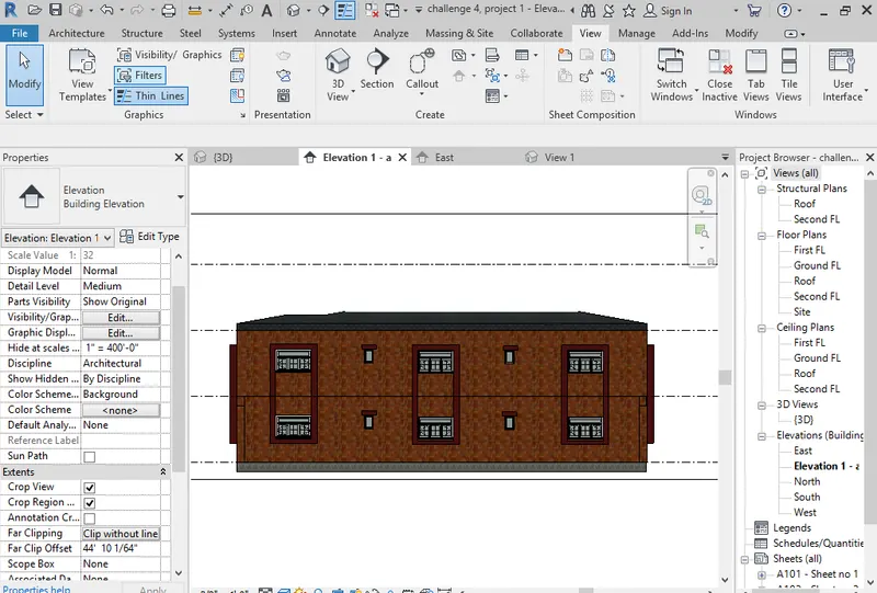
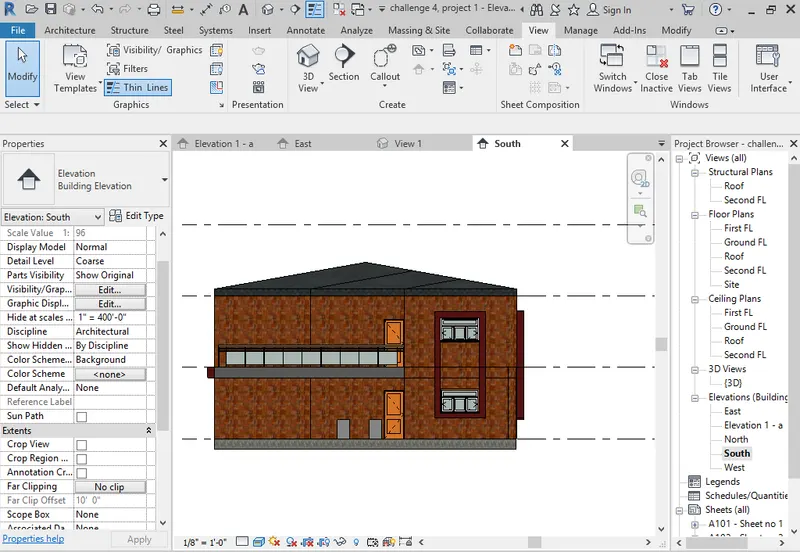
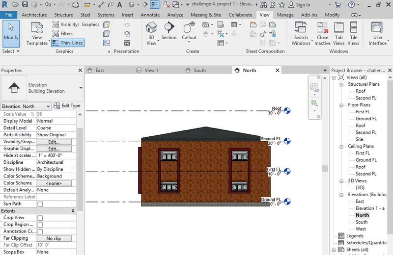
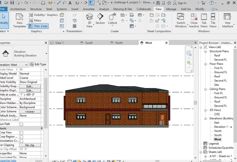
To create the elevation views, looking at your building from East, North, South and West using the elevation tab
INTRODUCTION:
- An elevation is a view of a building seen from one side
- This is the most common view used to describe the external appearnce of a building
PROCEDURE:
STEP 1
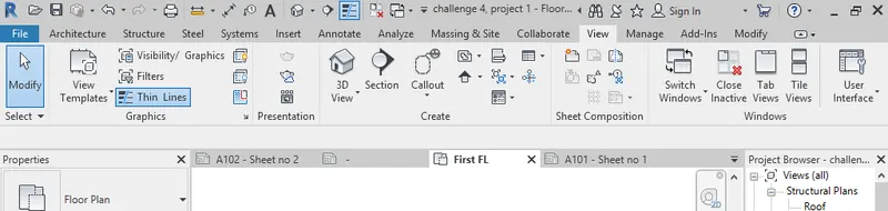
- Click on the elevation option from view tool bar
STEP 2
- Elevation from the east is visible
- Elevation from the south is visible
- Elevation from the north is visible
- Elevation from the west is visible
7.
AIM:
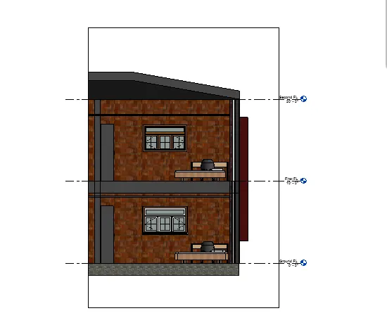
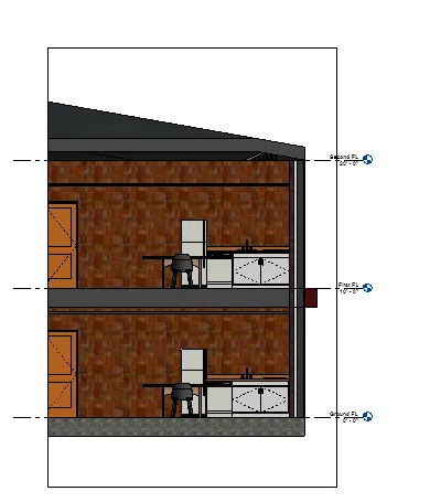
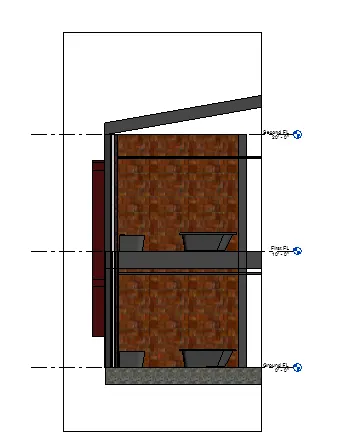
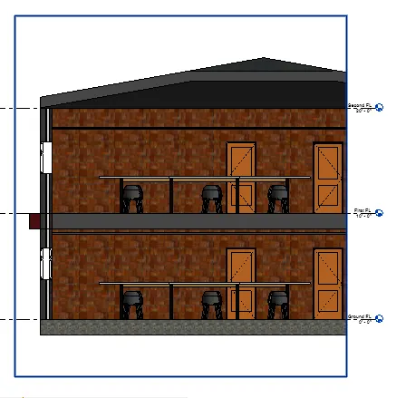
To produce section cut through each room either cutting across longitudinally or in a transverse direction
INTRODUCTION:
- Sectional views are used in engineering and architectural drawings
PROCEDURE:
STEP 1
- Click on the section option from view tool bar
- Sectional view of bedroom
STEP 2
- Sectional view of Kitchen
STEP 3
- Sectional view of Toilet
STEP 4
- Sectional view of Living room
RESULT
Succesfully completed the sectional views of all rooms
8.
AIM:
To classify the views, plan views, section views, and elevation views to either Design or Documentation category using properties browser.
INTRODUCTION:
- The structural plan view is the default view when you start a new project suing structural template
- Floor plan view is the default view in a new architectural projects
- Floor plans views are created automatically as you add a new levels to tour project
- Sectional views are used in engineering and architectural drawings.
- They help civil engineers, architects, and airplane designers communicate their ideas to their peers.
- An elevation is a view of a building seen from one side
PROCEDURE:
STEP 1
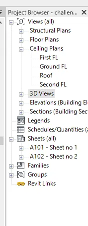
- Open the project browser, the views, Plan Views, Section Views, and Elevation views
STEP 2
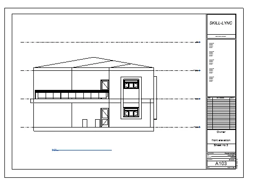
- Insert front elevation in a sheet template
STEP 3
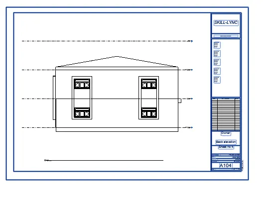
- Insert back elevation in a sheet template
STEP 4
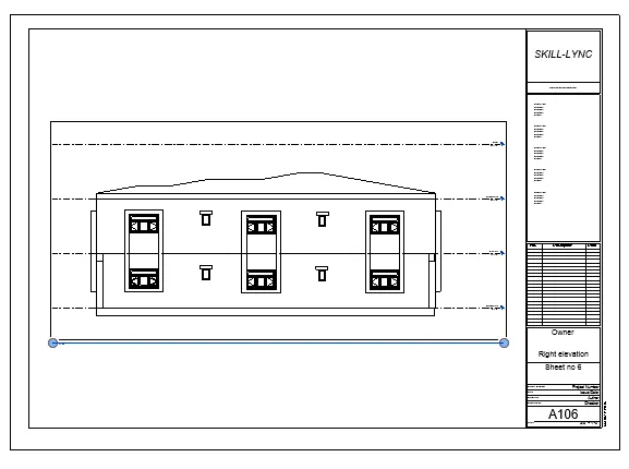
- Insert right elevation in a sheet template
STEP 5
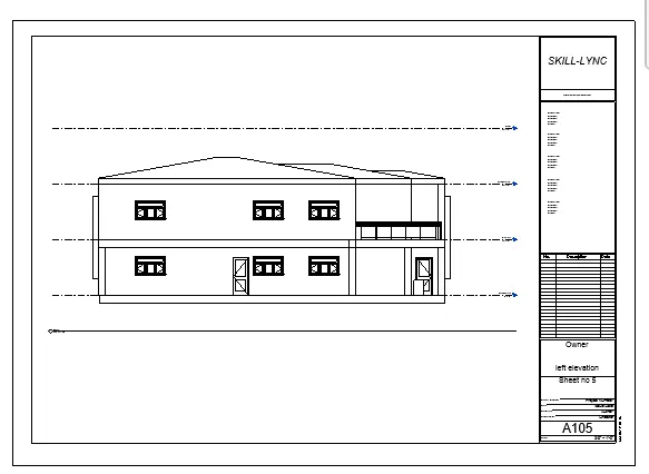
- Insert left elevation in a sheet template
STEP 6
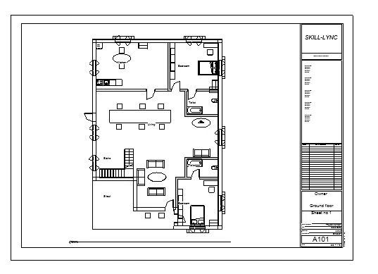
- Insert ground floor plan in a sheet template
STEP 7
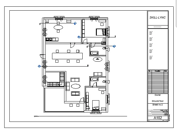
- Insert first floor plan in a sheet template
STEP 8
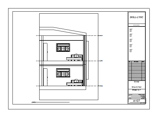
- Insert Bedroom section in a sheet template
STEP 9
- Insert Toilet section in a sheet template
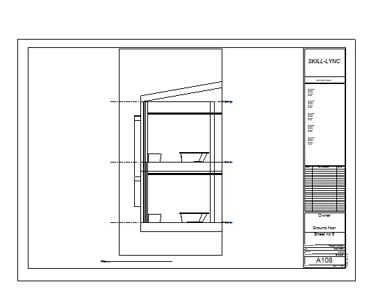
STEP 10
- Insert kitchen section in a sheet template
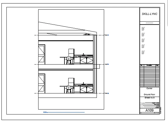
STEP 11
- Insert living section in a sheet template
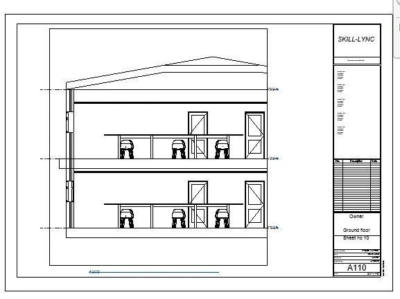
RESULT
Successfully completed the Views, Plan Views, Section Views, and Elevation views are classified to Design category using Properties browser.
9.
AIM:
To create the multiple sheets and produce the drawings in the sheets, from the given drawing list
INTRODUCTION:
- Create views on a project template before you start building the model to streamline the project documentation process.
- When creating a project template, you can include sheets in the template. Start with a blank project file, and create the standard views and levels that each project should include.
- Leave the views empty, but assign standard names to them. To create a standard set of construction documents, create sheets using the desired title blocks.
PROCEDURE:
STEP 1
- Create Ground Floor architectural plan in a sheet template A-101
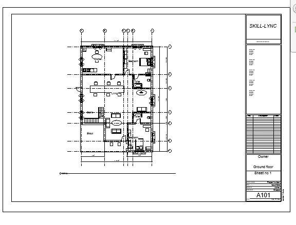
STEP 2
- Create First Floor architectural plan in a sheet template A-102
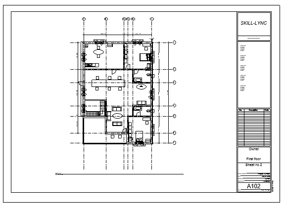
STEP 3
- Create Roof plan in a sheet template A-103
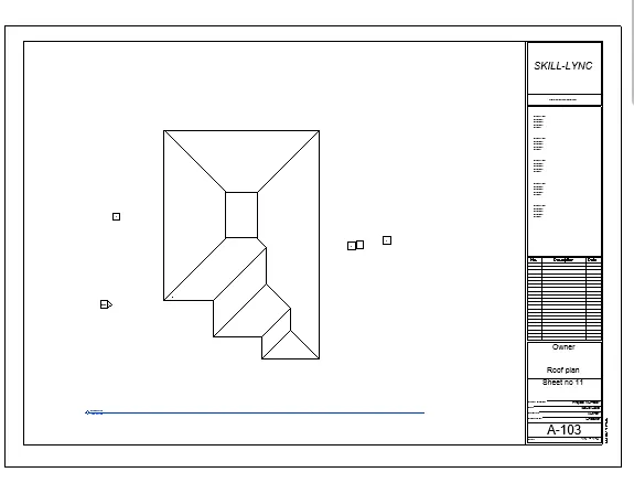
STEP 4
- Create Ground floor structural plan in a sheet template S-101
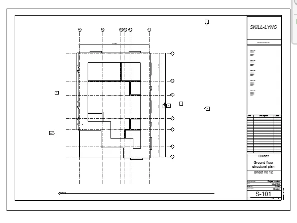
STEP 5
- Create First floor structural plan in a sheet template S-102
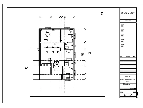
STEP 6
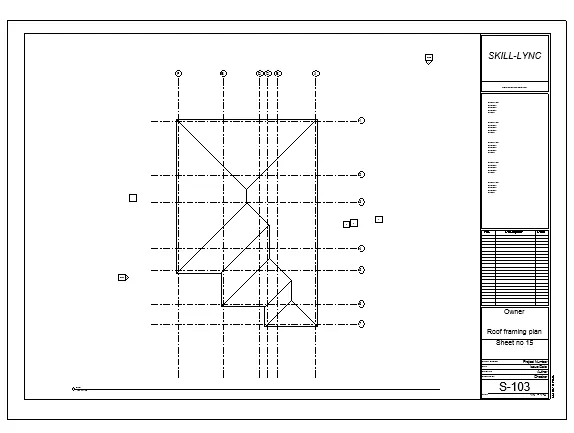
- Create Roof framing plan in a sheet template S-103
STEP 7
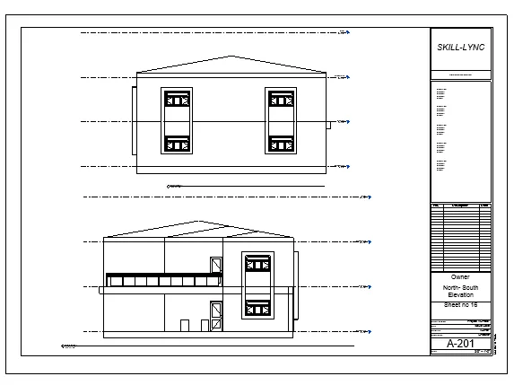
- Create North- South elevation in a sheet template A-201
STEP 8
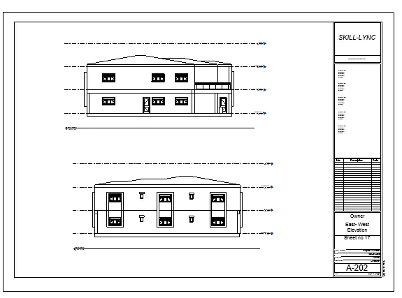
- Create East- West elevation in a sheet template A-202
RESULT
Successfully completed the multiple sheets and produced drawing in a sheet
10.
AIM:
To create a camera specific view or a 3D view in living room, dining room and bedroom in the sheets separately
INTRODUCTION:
- Camera Views are really useful in Revit.
- They allow us to view what we would actually see if we were standing at any given location in our design.
PROCEDURE:
STEP 1
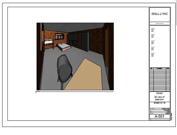
- Take a sheet and named as A-501
- Go to the floor plan , place a camera in the bedroom
STEP 2
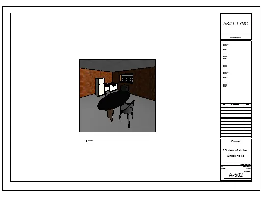
- Go to the floor plan , place a camera in the kitchen
STEP 3
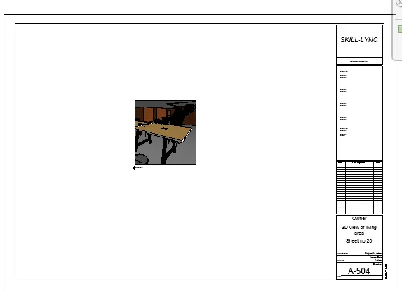
- Go to the floor plan , place a camera in the living room
STEP 4
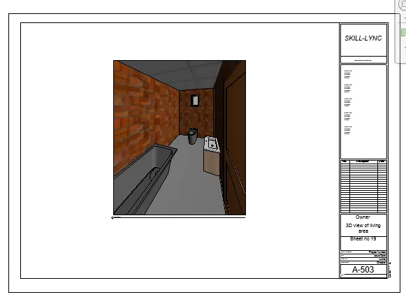
- Go to the floor plan , place a camera in the Toilet
STEP 5
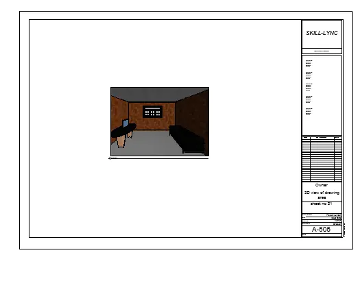
- Go to the floor plan , place a camera in the Drawing area
RESULT
Suucessfully completed the camera specific view or a 3D view in living room, dining room and bedroom in the sheets separately