3D Creation of Ceiling, Roof, Architectural plan, Structural plan, Sectional view, Elevation view and Camera specific view for a house plan using REVIT
1. Modelling of ceiling
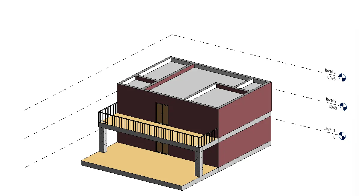
AIM :- To model a ceiling from the architectural tab above the walls at the first-floor level .
Procedure :-
. Open the project
. Click on first floor in plan view
. Click on ceiling from architectural tab
. Click on automatic ceiling
. Go to level 2 plan view and click on the rooms to create ceiling
. give the offset from level 2 in the property browser .
. Create ceiling above the open terrace by skeching
RESULT :- Ceiling is modelled above the architectural Plan .
2 . Modelling roof above the ceiling
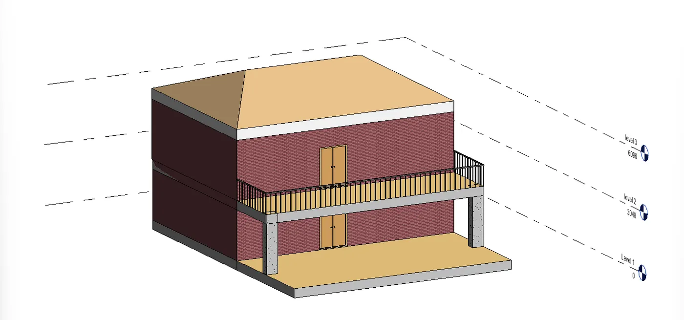
AIM :- To create roof above the ceiling and adjusting the roof slope to 10 degree .
Procedure :-
. Go to level 3 floor plan
. Click on roof tab under Architectural tab .
. Click on pick lines and draw lines coonect the roof line in level 3
. go to 3D view
. Click on 3d view
. We can drag the arrows provided to adjust the slopes
. In property browser , we can change the roof slope to 10 degree
RESULT :- Roof is created above the ceiling and slope is adjusted to 10 degree
3. Creating architectural and structural plans
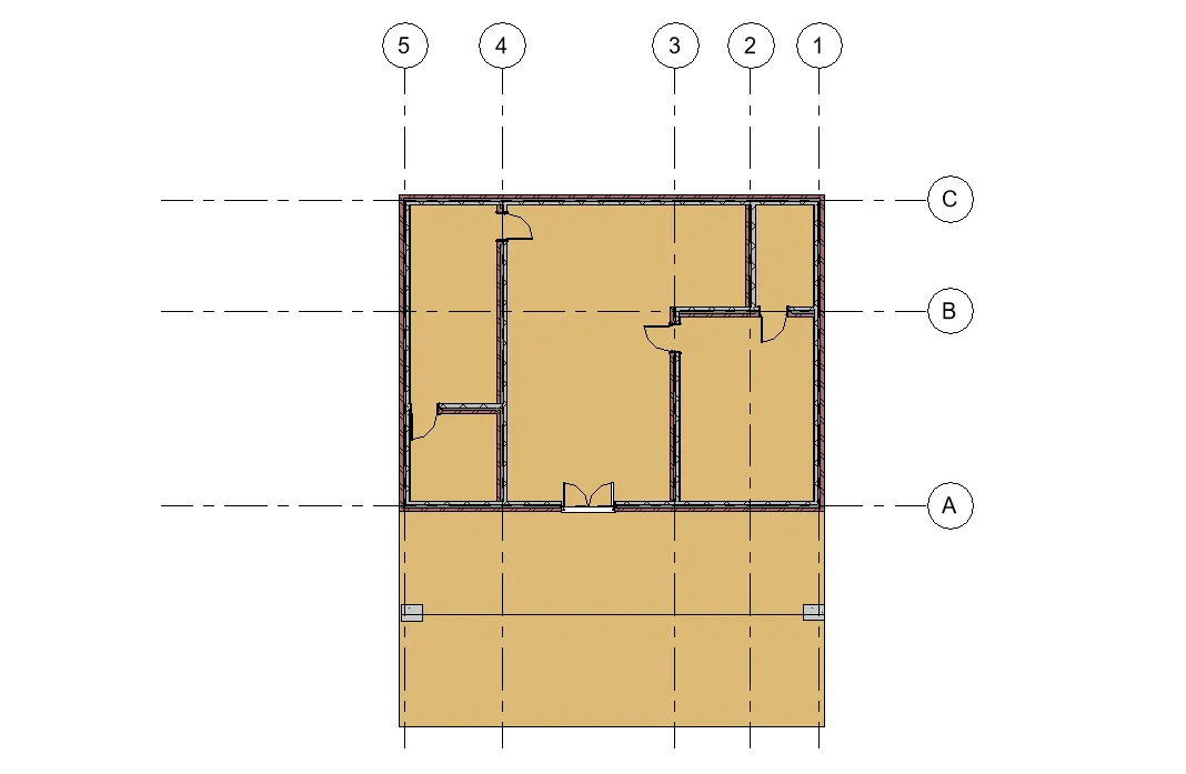
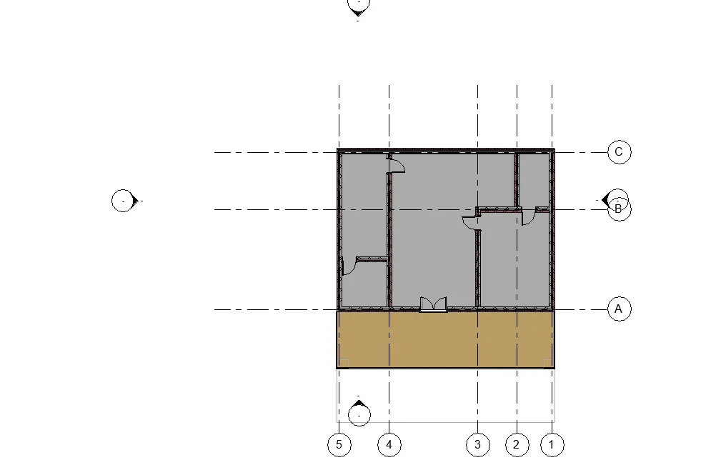
AIM :- To create plans view for ground floor and first floor levels and separates them to architectural and structural
Procedure :-
a) Architectural plan - wall , floors and all componenets inside building
. In architectural tab click on wall and draw the wall
. Click on doors and window tab under architectural and place it wherever required .
. Click on floors and click on pick lines and click on the outlines lines
. Click on place a component under architectural tab and if the components are present places it or click on load
family
. Load the components we need to place
. Place sofa and table , chair , tv , in the living room
. Place bed, table chair , cabinets in bedroom
. place hob and cabinets in the kitchen
. Pace washing machine cabinets in the store
. Similary by walls create the first floor and by floors create the floors
. Place doors and windows
. Place the component
. Sofa st chair in living room , bed and cabinets in bedrom reading table and chair and shelve in reading room
. water closet and wash basins in toilet
b) Structural plan : column and beams
. Create the wall by clicking walls in architectural tab
. create doors and windows
. floor is created by clicking on floor tab pick lines and select the lines
. Place the column by clicking on columntab under architectural tab
. Click on architectural column and place the colums in all coreneres of the wall and also wherever required
. similary place the column in all the corners and wherever requied
. Delete the walls and floors
. Select beam from structural tab , draw beams connecting columns
RESULT :- the architectural plan and structural plans has been created
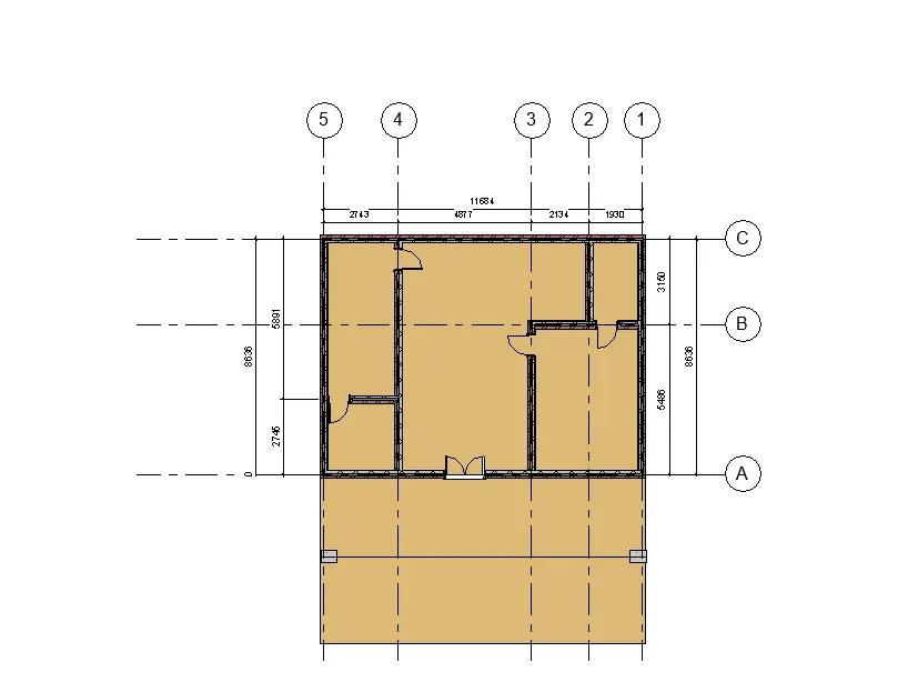
4. To add dimenssions to architectural and structural plan
AIM :- to add dimenssion using toolbar to the architectural and structural plans
Procedure :-
a) architectural plan : dimssions with respect to the grids
. The grids are created along the walls
. Click on annotate tab select linear dimenssion
. Click on two walls to get distance of the rooms
. Again click on annotate , linear and select the grid points and components
Dinning room
bedroom
store
restroom
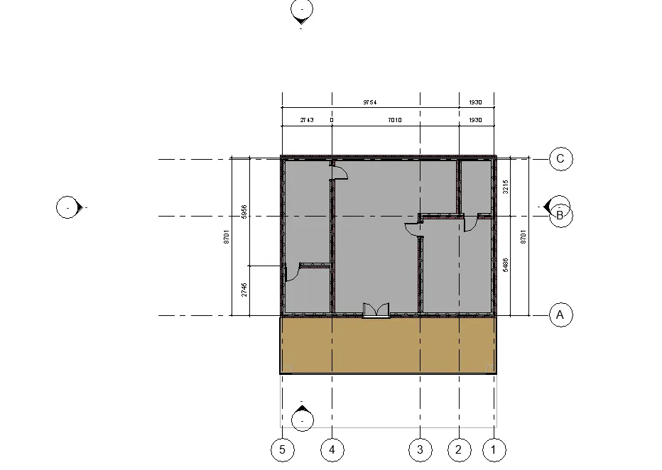
b) Structural : dimenssions with respect to the grids
. Create colums on all corners of wall
. Create beams connecting colums
. Using grid tab the grid at the centre of the column
. Use annotate tab , aligned and linear to measure the dimenssion between the grid grid and wall
. measure the dimenssion from grid annotation walls
RESULT :- Dimenssion with respect to the grids anr measured using annotate tool
5. Creating sheet template
AIM :- To create sheet template from the view tab and adjusting the parameter to add views
Procedure :-
. click on view tab select sheet options select A1 metric
. If we need sheet click on load button select title blocks and select the sheet we need
. A sheet will be created
. We can edit the template by double clicking the letters
. To add views click on place view under view tab
. Select the view created it in the sheet click on add view to sheet
. When adding if size is large click on size crop select scale and give a value and apply
. click on living and dinning view and add them
. click on 3d view of restroom and 3d view of full building and place in the sheet
RESULT :- Sheet template is created and views are placed in the sheet templates
6. Creating elevations
AIM :- To create the elevations views using elevations tab from north south , east , west
Procedure :-
. In view tab click on elevations in level view
. Places the view where we need , elevations 1 wiil be created in the property browser
. Click on elevation 1 to see the view
. Similary place the elevations blocks in north, south east , west and rename it respectively
. click on elevations tab from the project browser
.Expand the elevations tab from the project browser
. Expand the elevations tab we can see different elevations of north , south , east, west
. Click on east view
. click on north view
. click on south view
.click on west view
. to create more view elevations and places the elevations blocks to where we need the view
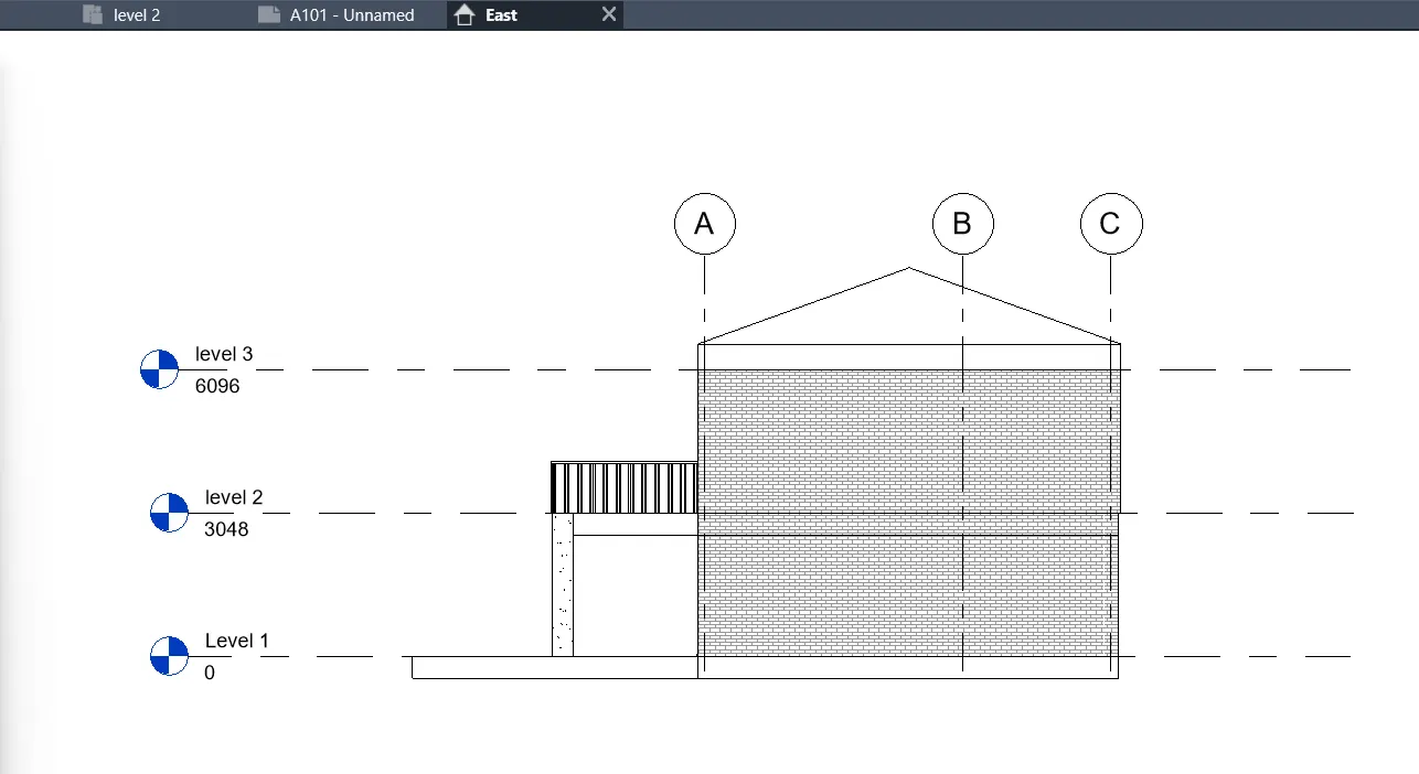
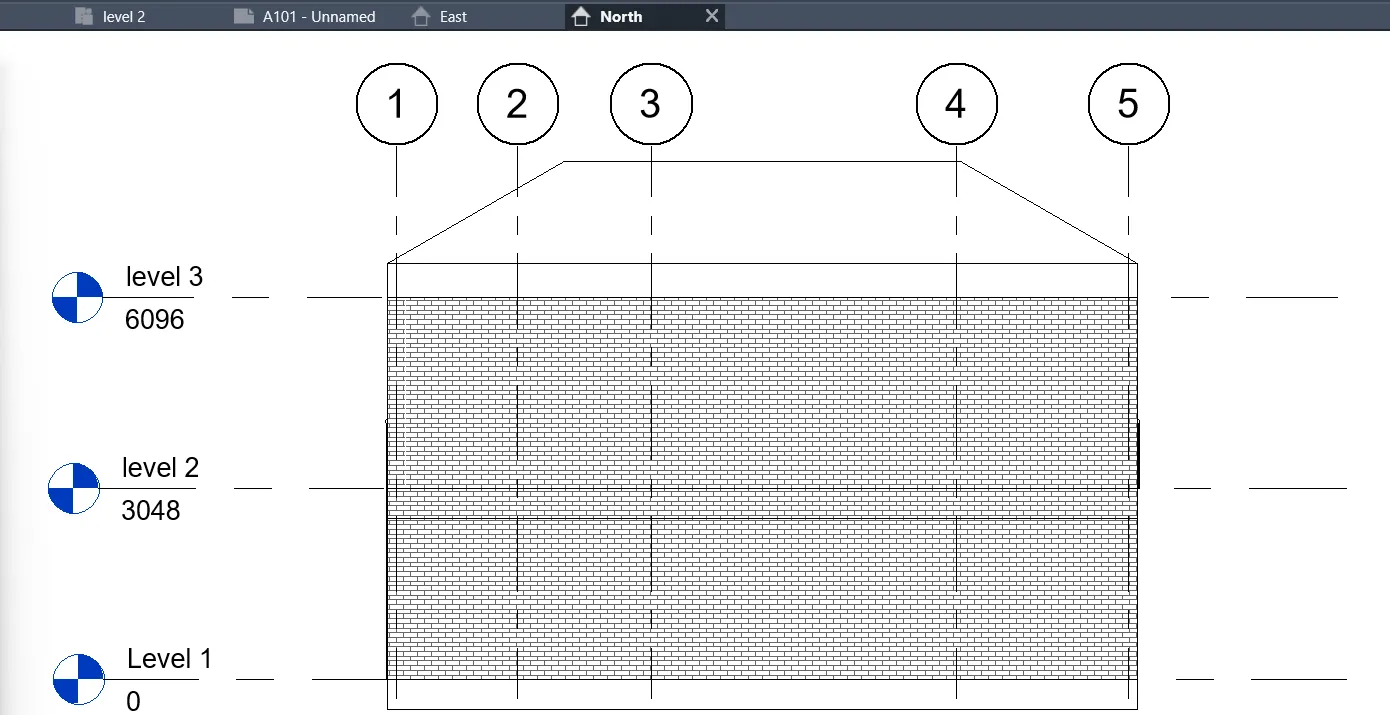
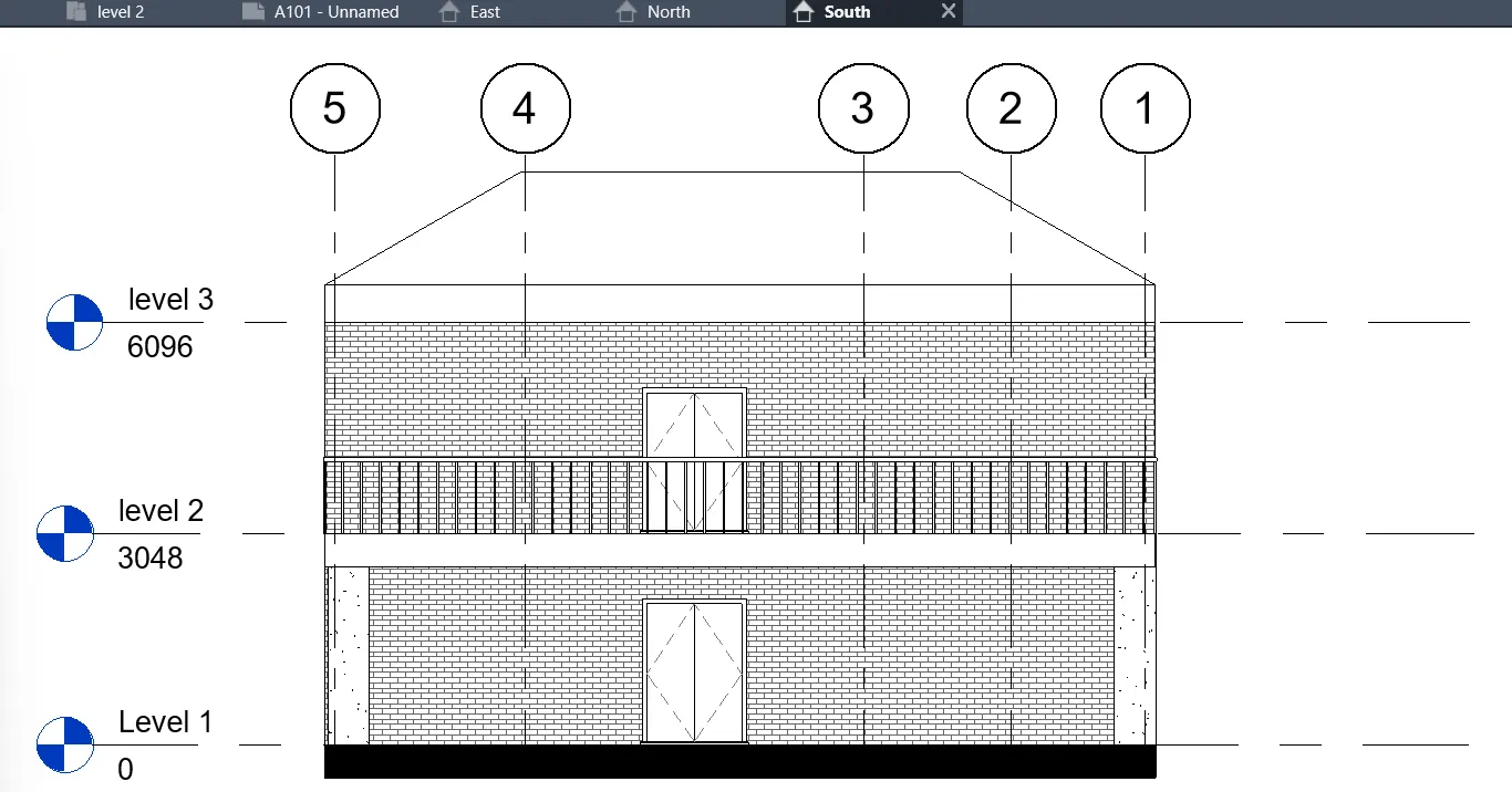
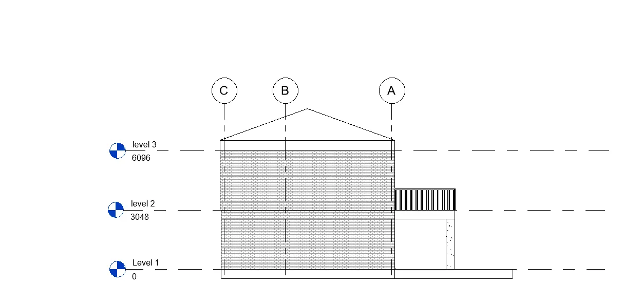
RESULT :- north , south , and west created using elevations tab
7. Sections cut through each room cutting longitudnally and transveresly
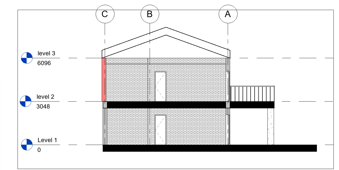
AIM :- To create section through each room creating sections logitudnally and transvesely
Procedure :-
. click on section tab from view tab , draw the sections through the living and dinning longitudanlly
.click on section view from the property browser we can see the view
. click on sections tab view from view and place the sections through the bedroom longitudnally
. click on section view and select the created section from property browser we can change the name by right
clicking abd rename it to bedroom
. click on bedroom view from the section tab
. click on sections tab from the property browser rename the selection to restroom
. click on sections tab from properly browser rename the selection to restroom
. click on sectioal view from tab and draw section line through transverse diection in kitchen
. click on section fom the property browser and rename it to kitchen and selection the view
. Create a longitudanally section for the kitchen
. Select the view from section under property tab
. click on section from view tab and crated a transvrse sections for the room
. Go to sections under property tab and change the name to store and select the view
RESULT :- Section view are created for
. Living room and dinning room
. Bedroom
. Rsetroom
. Kitchen
. Store room
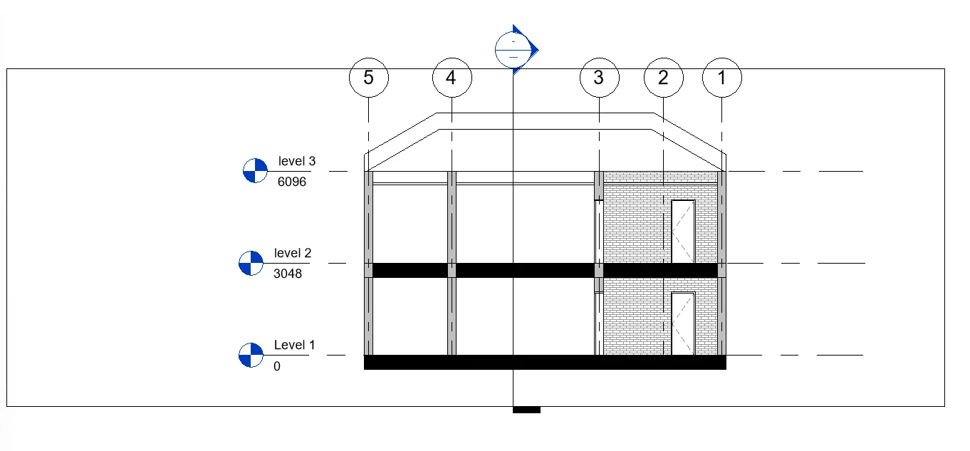
8. Classifying different views
AIM :- To classify different views like plan views , section views and elevations views and documents it in project
browser
Procedure :-
. In the properrty browser we can see all the views are invisible
. Click on each of the tab to expand it , so that we can see the plans elevations and sections view is crated
. For plan view click on the floor plans and expand it
. we can see that level 1 , level 2 , level 3 , which are created is visible
. select on each to see the floorplan on that level 2 is created at 10 ' and level 3 at 20'
. Select level 2 so that we can see the plan viewof first floor level
. click on elevations in property browser expand it and can see that different elevations view are there
. click on east to see the east elevations view
. click on north elevtions
.click on south elevations
. click on west elevations
. click on sections to expand the view
. selelct bedroom view
. select living and dinning
. select on kitchen
. selelct on store
RESULT :- views are classified and are documents in the projects browser
9. Creating multiple sheet from sheet templates
AIM :- Creating multiple sheets using templates
a) A 101 - Ground floor architectural plan
b) A 102 - First floor architectural plan
c) A 103 - roof plan
d) S 101 - Ground floor structural plan
e) S 102 - first floor structural plan
f) S 103 - Roof framing plan
g) A-201 - North south Elevations
h) A-202 - east-west elevations
Procedure :-
A) A101- Ground floor architectural plan
. click on create sheet from the view tab
. Select the sheet or load another if needed
. The sheet created will be visible in the project browser rename the sheet name as A101- Ground floor architectural
plan
. click on place view in th view tab a dialogue box appears
. Select floor plan level 1 click on add view to sheet
b) A102- First floor architectural plan
. Create another sheet from view tab new sheet
. Rename it to A102- first floor architectural plan
. click on place view under view tab
. Select floor plan level 2 Add view to sheet
c) A103- Roof Plan
. Click a create sheet from the view tab
. Rename the sheet name to A103 roof plan
. Select place view and place ceiling plan
d) S101- ground floor structural plan
. Select sheet from vview tab
. rename it to S101- ground structural plan
. click on place view from the view place the structural plan
e) S102- first floor structural plan
. Select the created column and change the top constrain to level 3 with base constrain as level 1
. Select sheet from the view tab
. Rename it to S102- first floor strucutal plan
. click on place a view from the tab
. place the view in the sheet and adjust the scale if needed here 1:50 scale is used
f) S103-roof framing plan
. Create sheet from the view tab
. Rename the sheet number and name to roof framing plan
. click on place view and place the roof in the sheet
g) A102- North-south elevations
. To create elevations in view tab click on elevations and place the elevations in between north and south and rename
created elevations as north-south
. click on sheet from the view tab
. Rename the number and sheet name to 102-north-south elevation
. click on place view and place the elevations north-south
. click on the viewport window and level and right click on the hidden element displayed the right click and there will
be an unhide elements click on reval again to exist from it
. Place the image inthe centre
h) A202-East-west elevations
. create elevations from the view tab elevations and place the elevations between east and west
. Expand the elevtions tab and rename it to east -west elevations
. Create sheet from the view tab -sheet and rename it to A202 east-west elevations
. click on place view and sheet the east-west elevations created
I) Sections
. create sections by clicking sections tab for each room
. As the sections are already created . create sheet and place them in each sheet
. click on sheet from the view tab rename it as A203-section living
. click on place view and place the sections view created
. created sheet for dinning from view tab A204- dinning sections
. place the sections view dinning
. created sheet from view tab and rename it as A205 section bedroom
. click on place view and place the sections of bedroom and adjust the scale
RESULT :- respective sheets are created using sheet tmplates
a) A 101- Ground floor architectural plan
b) A 102 - First floor architectural plan
c) A 103 - Roof plan
d) S 101 - ground floor structural plan
e) S 103 - roof framing plan
f) S 102 - fist floor structural plan
g) A 201 - north south elevations
h) A 202 - east -west elevations
10. Creating camera view for each room and creating sheet for the views
AIM :- Creating camera view for each rooms and creating sheet for each of the 3d view
Procedure :-
Creating views :-
. Go to floor plan From the view options 3d view click on camera and place the camera in which room we need the
view
. Created views will be seen under 3d in property browser
Living :-
. Place the camera in the living room in the floor plan
. click on the 3d view created from the property browser and rename it to living
Dinning :-
. click on camera from view tab under 3-d view
. Place the camera such that the dinning view is visible
. Expand the 3d view from the property browser and rename it to dinning
. click on the dinning room
Bedroom :-
. click on camera from view tab under 3d view
. Place the camera such that the bedroom view is visible
. Expand the 3d view from the property browser and rename it to bedroom
. click on the beroom view
Kitchen
. click on camera from view tab under 3d view
. Place the camera such that the kitchen view is visible
. Expand the 3d view from the property browser and rename it to kitchen
. click on the kitchen view
Rest room :-
. click on camera from view tab under 3d view
. place the camera such that the restroom view is visible
. Expand the 3d view from the property browser and rename it to restroom
. click on the restrooms views
Store :-
. click on camera from view tab under 3d view
. place the camera such that the restroom view is visible
. Expand the 3d view from the property browser and rename it to store room
. click on the restrooms views
Creating sheets :-
. To create sheet to go view tab click on sheet select the sheet we need or load more and select the required
. rename the sheet name As A501- living room
. click the place view and click on the living from the dialogue box
. Create another sheet from the view tab rename it to A502-dinning room
. click on place a view and select the dinning room
.Create another sheet from view tab and rename it to A503 bedroom
. click on place a view and place the bedroom view
. Create new sheet from a view tab and rename it as A504-kitchen
. click on place view and place the kitchen view
. Create another sheet and rename it as A505-restroom
RESULT :- camera view of all rooms are created and sheet are created accordingly views
. Living
. Dinning
. Bedroom
. Restroom
. Kitchen
. store
Sheets
. A501-living room
. A502- Dinning room
. A 503 - Kitchen
. A 504 - Restroom
. A 506 - Store