22. Wiring harness design in CATIA V5 - 3D modeling Week 5 & 6 Challenge
Wiring harness design in CATIA V5 - 3D modelling Week 5 & 6 Challenge
Aim:
- Route two electrical harnesses per the given layout and interconnect them as a single harness assembly
- check for bundle continuity, and bundle warnings, and then provide annotations for the final harness assembly.
Objective:
- The objective of this project is to first route the two Harness A and Harness B as per the given harness layout.
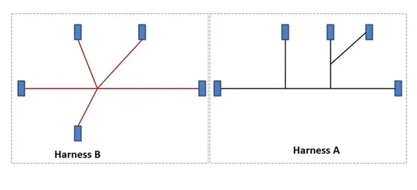
Figure 1: Shows the layout of two Harness A and Harness B
The electrical connectors are represented by numbers in the above figure. There are 8 different types of connectors at 10 different locations. All connectors are added in catlog after defining them electrically to use them after.
- First step is to define all connectors electriacally, add them in mechanical assembly first constrain them properly then define them as electrical harness assembly by using geomtrical bundle option.
- Bundle continuity has to be checked for the two created harnesses.
- After the two Harnesses are created, the next objective is to have them interconnected electrically.
- Check for bundle warnings in Harness A and Harness B.
- Add annotations to all the connectors in Harness A and Harness B.
Step-1:
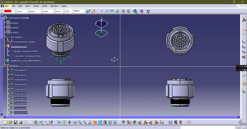
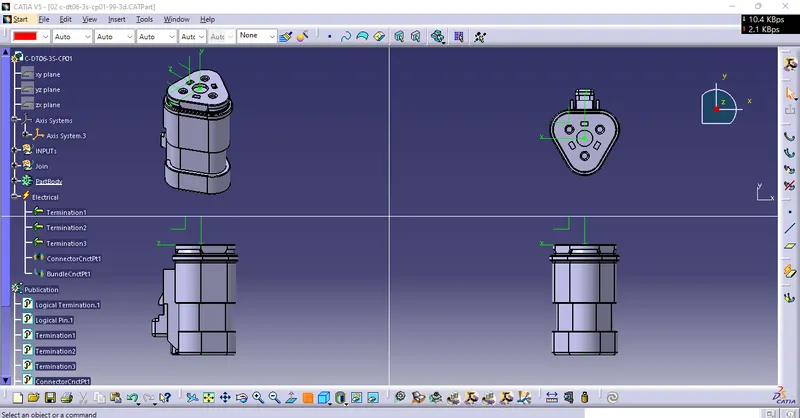
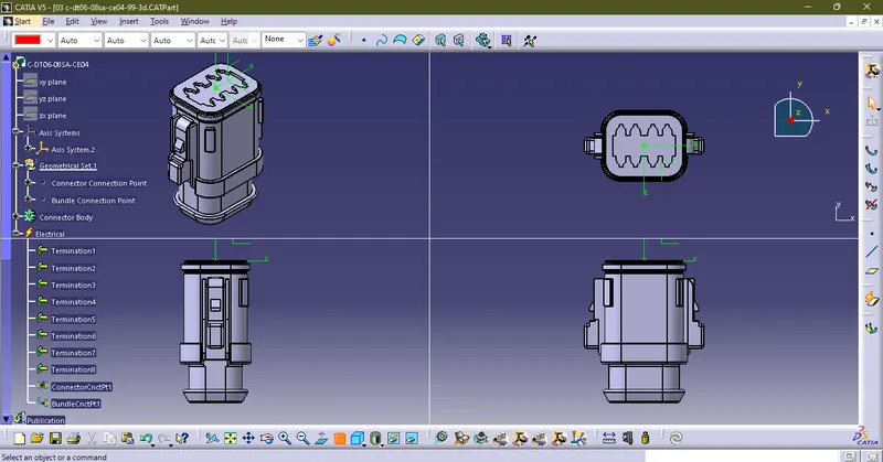
Define all the electrical connectors geometrically and electrically so that they can be used in the wiring harness.
1.C-YDTS26F15-35SNV001
2.C-DT06-3S-CP01
3.C-DT06-08SA-CE04
4.C-DT06-08SA-EP07
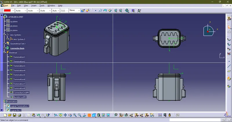
5.C-DT06-08SA-CE13
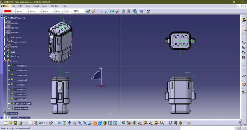
6.C-DT04-08PA-C017
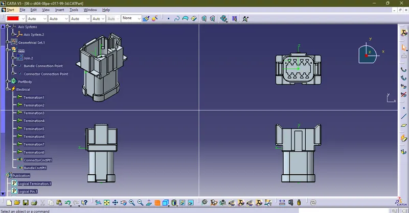
7.C-2-174357-2
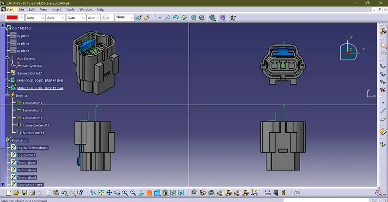
8.C-DT06-08SA-CE01
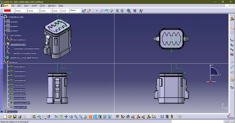
9.C-DT06-08SA-EP07
10.C-YDTS26F15-35SNV001
CATLOG FILE IS THEN CREATED AND ALL 8 CONNECTERS ARE STORED IN IT TO REUSE THEM USING "STORE DEVICE" OPTION INSIDE ELECTRICAL PART DESIGN. WE HAVE TO PLACE THEM IN 10 DIFFERENT LOCATIONS.
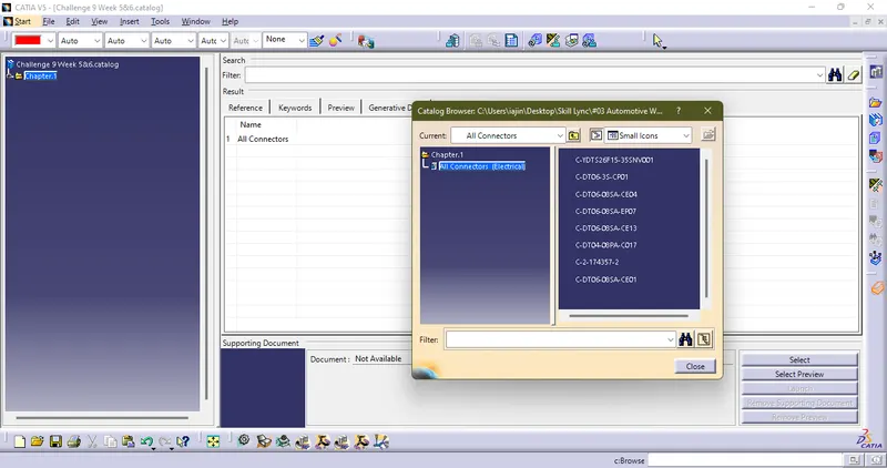
HARNESS A
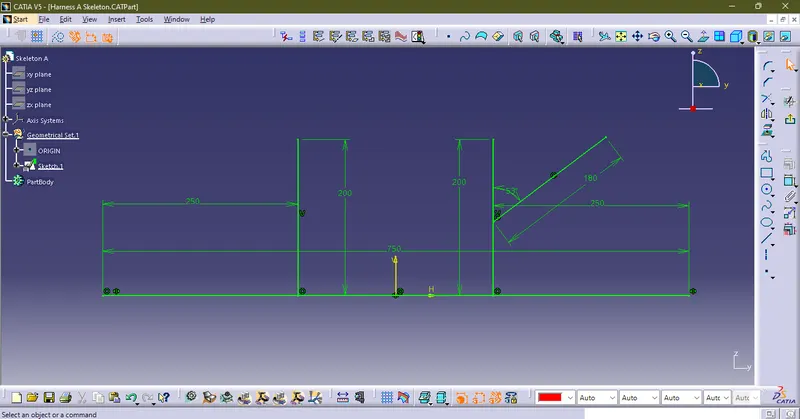
To Place Connectors Properly I have created skeleton of Harness A and Dimensions are assumed.
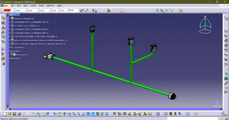
All Connectors from 6 to 10 are added in single assembly File and are constrained
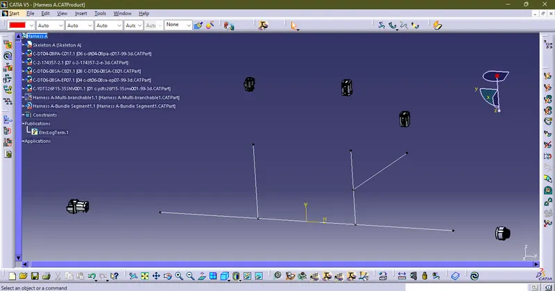
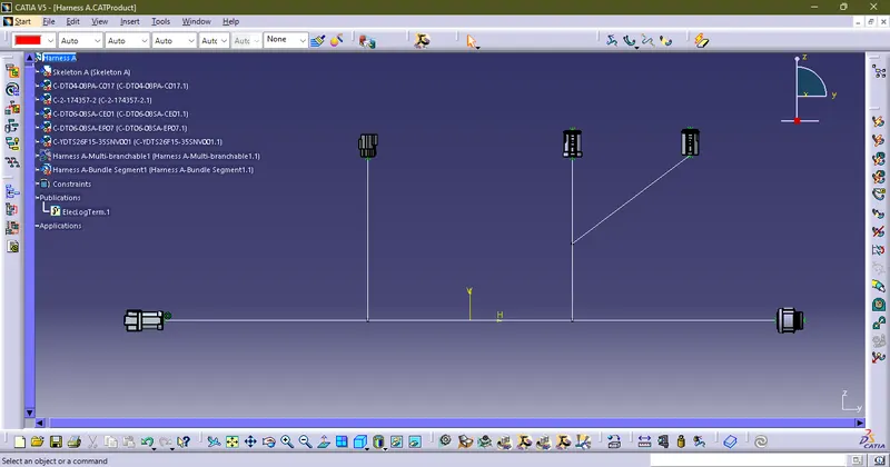
Then Start Routing the bundle
HARNESS B
Skeleton For Harness B
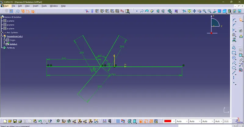
All Connectors from 1 to 5 are added in single assembly File and are constrained
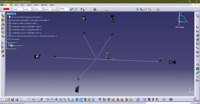
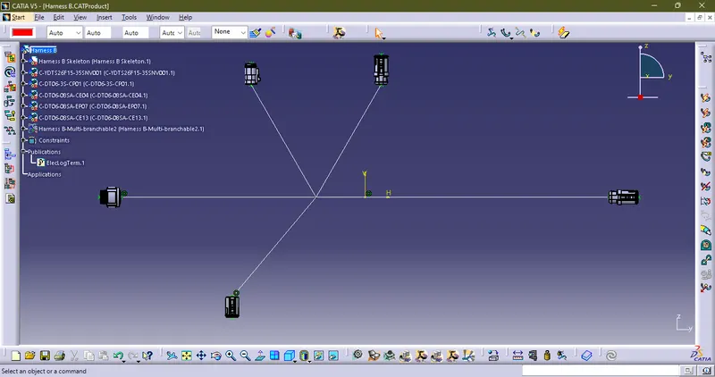
Then Start Routing the bundle
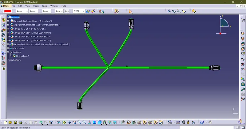
1.Now we have 2 Harnesses
2.Harness A & Harness B and we have to create assembly between them
3.Create another Assembly
4.In it add Harnesses A & B and constrain mating faces using Surface contact and coincidence commands in mechanical assembly.
5. to make in eletrically defined use Geometrical Bundle option.
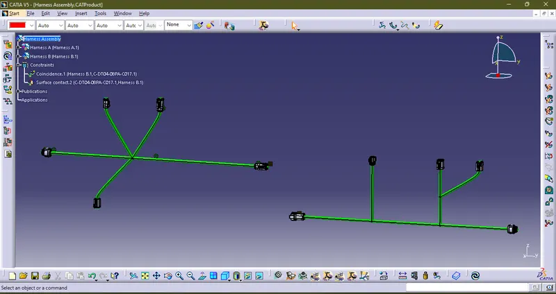
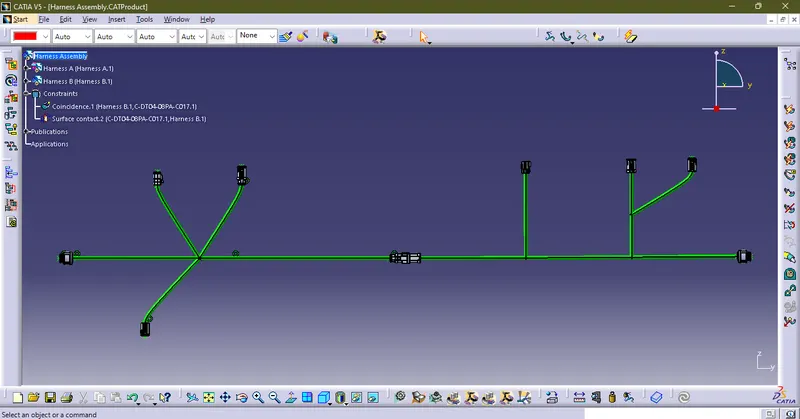
ALL FILES ARE ADDED IN A SINGLE ZIP FILE ATTACHED BELOW