19. Wiring harness routing & packaging Rules Week 3 Challenge
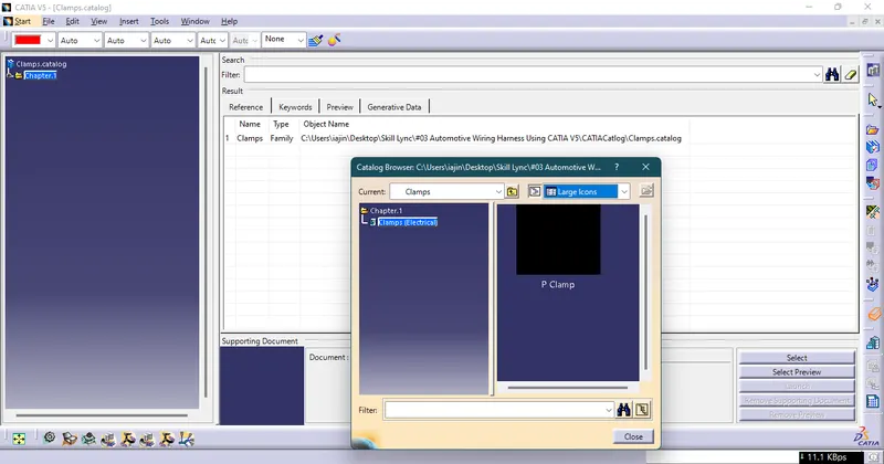
Q1. P CLAMP:
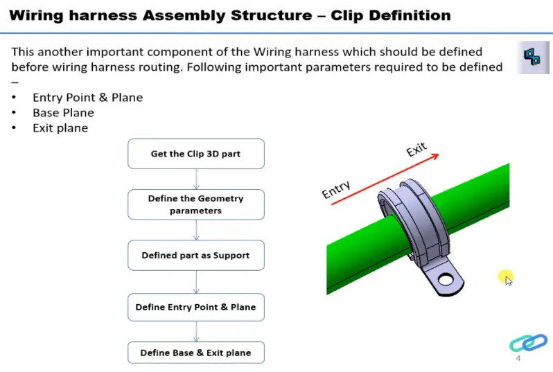

STEPS:-
1. First create an Entry point and Plane.
2. Create Exit point and Plane.
3. Add base Plane for it.
4. Click "Define Support Part"  .
.
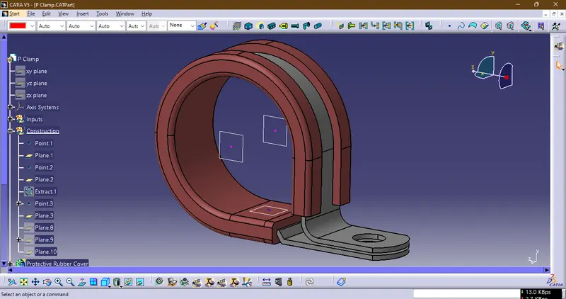
5. To define give First point as a Entry Point & below that select Plane on which that Point resides.
6. Give Exit Plane as Plane opposite to Entry Plane.
7. Give Base Plane As Support.
8. Repeat the same process on Alternate Point and Respective Plane.
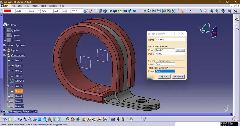
9. After All Above steps followed correctly add the part in the respective catlog or create an new one.
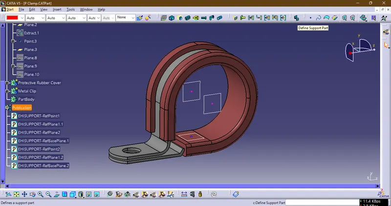
10. Part Added into Catlog Using "Store Devices"
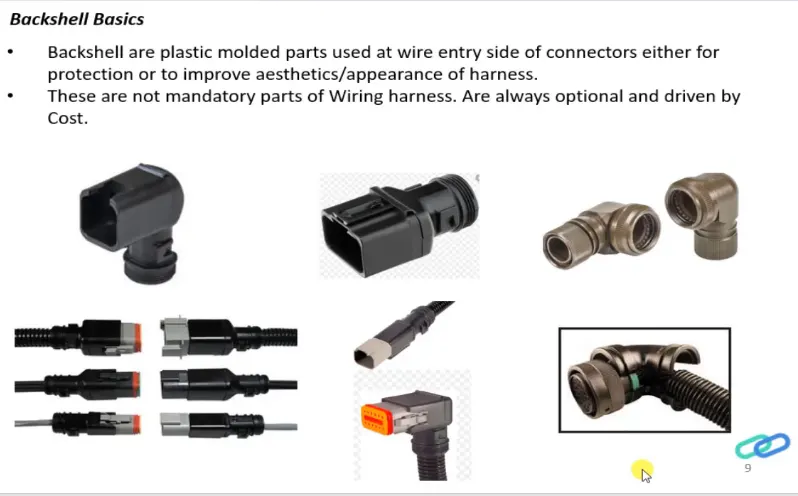
Q2. Download following Back shell cad data & define it as Electrical back shell using Electrical Part design Workbench. Define all the necessary properties.
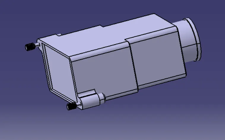
Tyco 1738312-1 Backshell
STEPS:-
1. Download and Open the given part in "Part Worbench" in CATIA.
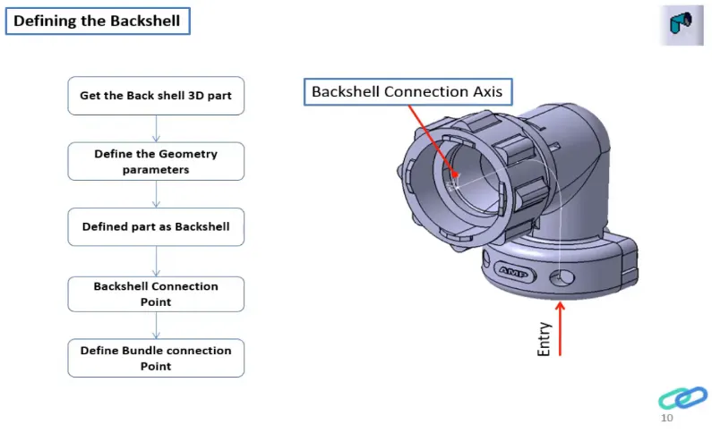
2. Create Bundle connection Point and Connector Connection Point & Create axis system on each Point.
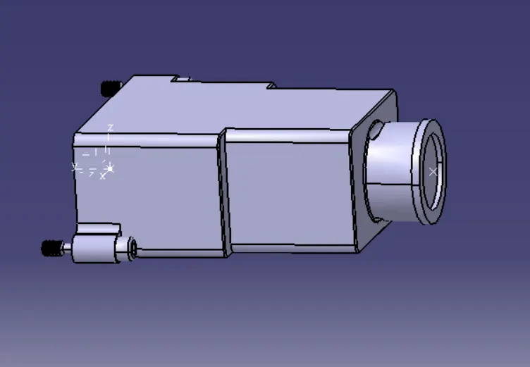
3. Open "Electrical Part Workbench" define as Backshell.
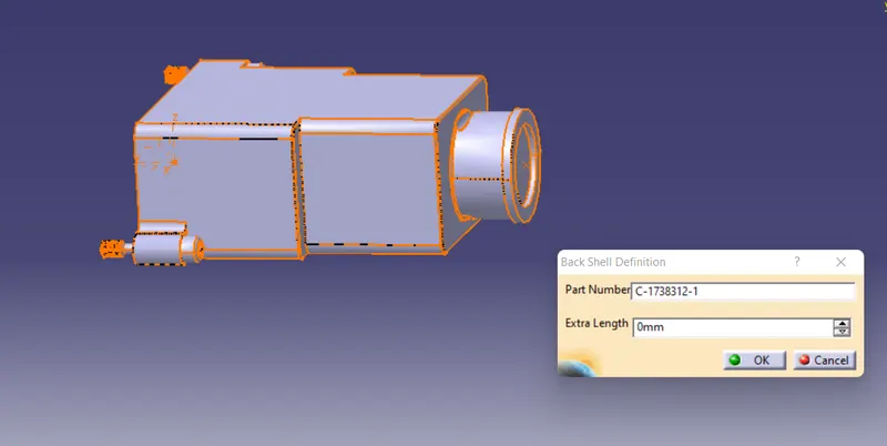
4. Define Bundle Connection Point and Backshell Connection Point.
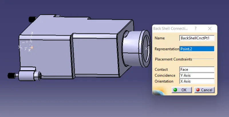
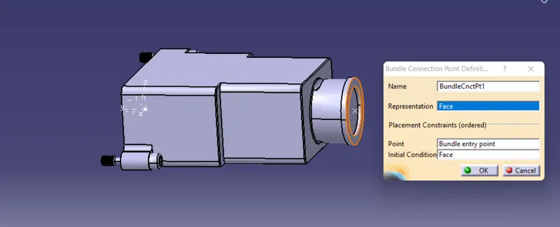
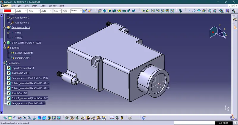
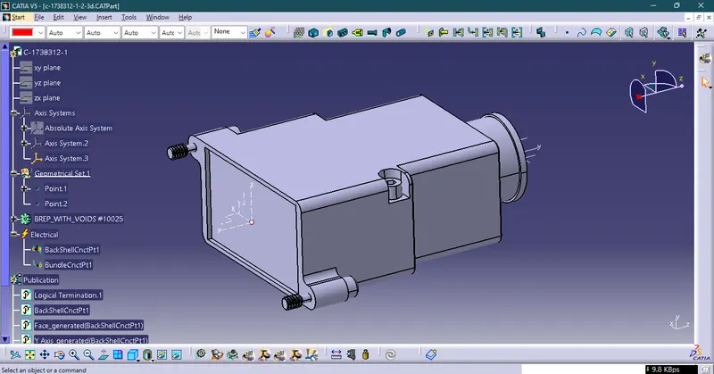
5. Finally after defining given part mechanically and electrically, add the backshell into new catlog named Backshell Using "Store devices" Command
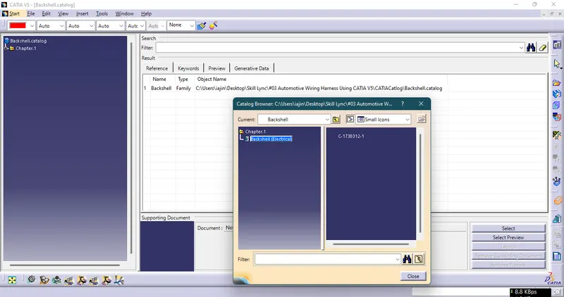
Q3. Create Following Corrugated tubes & Add them in Catalogue under “Slit COT” family.
|
Name |
ID (mm) |
OD (mm) |
Thickness (mm) |
Ideal Bend Radius (mm) |
|
15mm COT |
12 |
15 |
1.5 |
23 |
|
20mm COT |
17 |
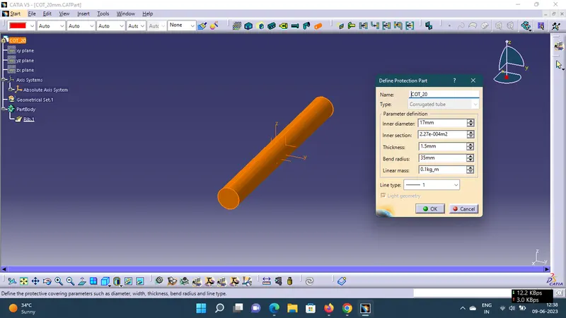
20 |
1.5 |
35 |
|
35mm COT |
32 |
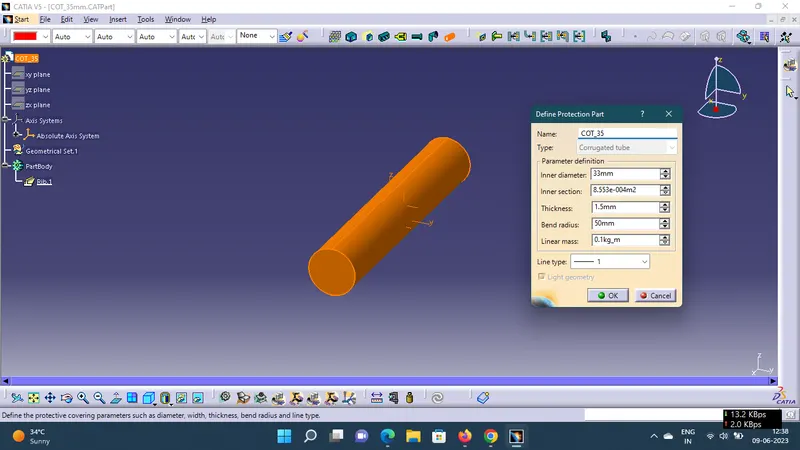
35 |
1.5 |
50 |
|
10mm COT |
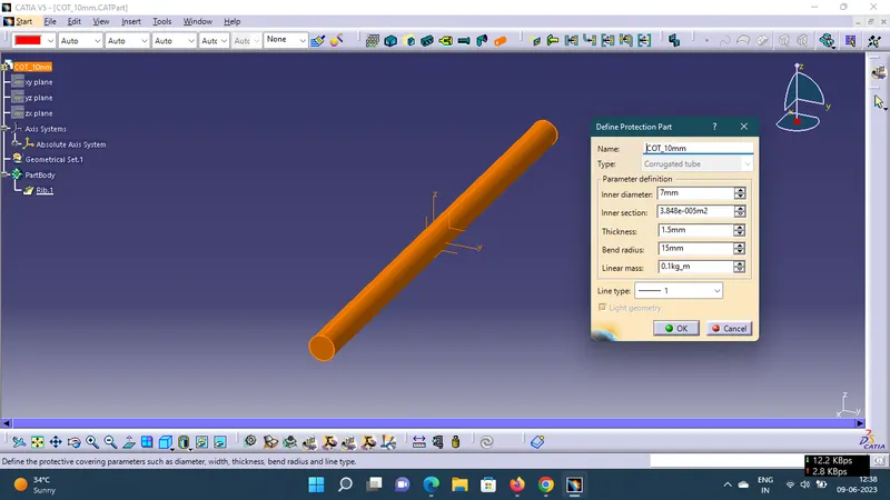
7 |
10 |
1.5 |
15 |
|
5mm COT |
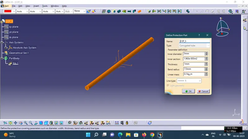
3 |
5 |
1 |
7.5 |
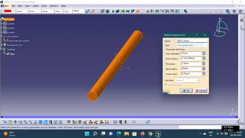
Steps To Create Corrugated Tubes:
1. Open the Electrical Part Workbench.
2. To define click Protection Part & Click axis to define parameters
3. It is noted that Ideal bend radius is 1.5 X OD
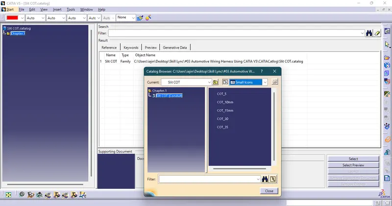
4. After creating corrugated tubes add them one by one using store device command Create Catlog Named Slit cot.
1. 15mm COT
2. 20mm COT
3. 35mm COT
4. 10mm COT
5. 5mm COT
FINAL CATLOG
ALL FILES ARE ADDED IN ZIP FILE ATTACHED BELOW