#10 Duty Cycle
Question
- Why power electronics circuits are efficient? In practice, which types of losses occur in power electronics circuits?
- A. Develop a Simulink model for generating pulses for a simple power converter circuit? (Hint: Blocks : sine wave,carrier wave,relationaloperator,scope) B. Simulate a simple power converter circuit (Default) with the above results.
- Explain the difference between VFD and Vector control drive. Can we use VFD method for induction motor in EV application?
Use the "INSERT CODE SAMPLE" option to paste your code.
SUBMISSION RULES
Use the "INSERT CODE SAMPLE" option to paste your code and attach screenshots of the output. 10 points will be reduced for not doing so. Just showing the code and not explaing the results. 20 points will be reduced if this happens.
If your program or model fails to compile then you will score 0, in that particular challenge. This is applicable only for challenges where you are asked to code or submit the model files
Create a zip file with all the necessary .m files model files etc. in google drive and them as a single zip file.
Copying code from others - If you copy code from others, your score will be 0. If you copy from others on more than 1 assignments your challenges will no longer be graded. You can still access the course but your challenges will not be graded.
If you have attached links to images or videos, make sure that they work before you hit submit. At the time of grading broken links will not be taken into account.
Once graded future submissions will not be valid
Make sure you provide open links while attaching Google Sheets file
Make sure you follow the constraints given in the question, violating them will results in 0 marks.
GENERAL INSTRUCTIONS:
The codes, plots, images, GIFs, and videos should be submitted only through the answer box.
Use the Google Drive to share only the cad models or other answers which couldn't be done through the answer box.
NOTE:
Violating the above instructions will lead to ZERO marks.
Link sharing should be enabled while sharing the Google Drive link, else the challenge will be awarded ZERO marks.
Your Answers
1.Why power electronics circuits are efficient? In practice, which types of losses occur in power electronics circuits?
What are Power Electronics?
The increasing focus on electrification for a cleaner environment has fueled the need for electric power in different forms. Power electronics is the branch of electrical engineering that deals with the processing of high voltages and currents to deliver power that supports a variety of needs. From household electronics to equipment in space applications, these areas all need stable and reliable electric power with the desired specifications. Power supply in one form is processed using power semiconductor switches and control mechanisms to another form, supplying a regulated and controlled power. While switched-mode power supplies are a common application of power electronics where power density, reliability, and efficiency are of prime importance, motor control is gearing up with more electrification in transportation systems. Precise control and efficiency are key characteristics for power control applications. The study of power electronics is thus multidisciplinary, involving semiconductor physics, electrical motors, mechanical actuators, electromagnetic devices, control systems, and so on.
In power generation, especially in renewable energy, the generated power must be processed to meet the AC voltage specification of the power grid. For instance, a solar cell generates DC power whose output power varies with the operating voltage and incident solar irradiation. It is important to extract the maximum power available at the output of the cell and transfer it to the grid with the highest possible efficiency. So, the interface that connects the solar cell to the grid should provide AC power that matches the grid specifications and draws input power that operates the solar cell at its maximum power point. In addition to this, the conversion of this DC power to AC power should be with higher efficiency to minimize the losses in power generation. This is possible using power semiconductor devices with advanced control mechanisms that monitor the output and input parameters and control the switches.
Advancements in power semiconductor devices have paved the path for newer devices such as silicon carbide, gallium nitride field effect transistors (FETs), and power diodes. These devices have superior characteristics in terms of wide band gap that allows for high-voltage operation, thermal management, and efficiency. This has resulted in widespread usage of power electronics even in noise-sensitive areas, replacing the lossy linear power supplies and voltage regulators. The main advantage of these devices is that they can withstand high voltage when compared to the silicon devices. Thus, the systems can be designed with high-voltage capabilities, which, in turn, reduces the current and improves efficiency, for the same power to be delivered. In addition to this, operating the devices at higher switching frequencies helps in reducing the size of passive components, making the systems compact. The ability to handle higher temperatures simplifies thermal designs.
How Do Power Electronics Work?
Power electronic systems are used in a variety of applications, such as:
- Power Generation
- Power Transmission
- Power Distribution
- Power Control
In all these applications, the input voltages and currents are switched using power semiconductor devices to provide desired outputs. The construction of basic semiconductor devices such as diodes, FETs, and bipolar junction transistors (BJTs) are altered to withstand high voltages and currents. As a result, we have silicon-controlled thyristors (SCRs), power diodes, power metal oxide semiconductor field effect transistors (MOSFETs), power BJTs, insulated gate bipolar transistors (IGBTs), gate turn-off thyristors (GTOs), and so on. The device selection is based on the power levels, the switching frequency requirements, efficiency, and the nature of inputs and outputs. For instance, in an EV powertrain, the power handled is of the order of kW. In such applications, power MOSFETs which can withstand the high voltage and switch at higher frequencies are commonly used. In the case of power transmission, where the handled power is of the order of few megawatts, silicon-controlled rectifiers (SCRs) are used.
The block diagram of a typical power electronic system is shown in the figure below.
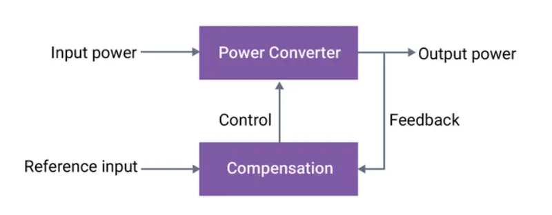
The primary element in a power electronic system is a switching power converter. The power converter consists of power semiconductor devices that are turned on and off at high frequencies. This operation switches the voltage and current through the devices, delivering a controlled power at the output. In addition to this, the power drawn from the input can also be controlled. An ideal device switches the voltage and current instantaneously and offers zero resistance once turned on and infinite resistance when turned off. But in the real world, no device can be switched instantaneously. The switching converters are associated with two types of power losses in the devices:
- Switching Losses
- Conduction Losses
The switching losses occur during turn on and off. For instance, when a switch turns on, the voltage across the switch goes to a low value from the voltage that was being blocked when it was in the off state. At the same time, the current through the device goes from zero to the load current level. Since this process takes finite time and the voltage and current are transitioning, power loss takes place. The transition is reversed when the switch is turning off. These losses constitute the switching losses. The switching losses increase with the switching frequency. To minimize these losses, several methods, such as zero voltage switching and zero current switching, are implemented using additional capacitors and inductors.
Conduction losses are a result of the finite on-state voltage drop across the switches during conduction. Availability of newer semiconductor devices and advancements in device structures are helping to reduce the conduction losses.
To control the switches, a control circuit, commonly known as a compensation circuit, is used. This block plays a pivotal role in minimizing the losses, delivering power efficiently and with good quality. The control block gets the reference and feedback signals as input and gives switching signals as outputs. Present-day controllers are mostly digital where the feedback is converted from an analog to digital signal and input to a signal processor. Compensation logic is implemented in the software that runs on the processor, and appropriate switching signals are generated. These signals are passed through drivers to provide sufficient power to drive the switching devices. Traditionally, analog circuits using operational amplifiers and comparators are used in compensation circuits. While providing appropriate gating signals to the switches, the control circuits also monitor the health of the system and inhibit the power output when faults occur.
Types of Power Electronic Circuits
As mentioned in the previous sections, power electronic circuits control the input and output power. There are several types of power converters based on the type of application. When we consider the power source, there are two main types of power sources, namely alternating current (AC) and direct current (DC). This forms four basic types of power electronics circuits shown in the figure below.
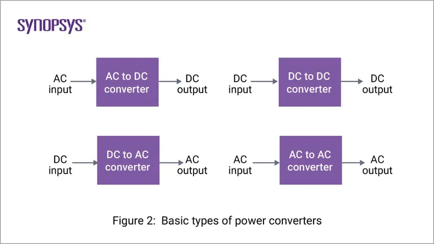
1. AC-to-DC Converters
The input AC voltage is converted to DC voltage at required levels. A diode bridge rectifier is traditionally used for these applications. But this configuration results in currents that have high peak values and high harmonic content. Boost converters are commonly used to draw currents that are in phase with the AC voltage.
2. DC-to-DC Converters
The DC power input, whether unregulated or regulated, is converted to regulated DC power at the output. Without power electronic converters, it is very difficult to generate variable DC power. With the availability of different configurations of DC-to-DC converters, DC power at desired levels has become indispensable. Buck, boost, and buck-boost converters are three basic converters that can step down, step up, and provide both levels, respectively.
3. DC-to-AC Converters (commonly known as inverters)
The input DC power from batteries is inverted to provide AC power. This AC power is used to control AC motors with precision and efficiency. A combination of AC-to-DC and DC-to-AC converters are used in high-power transmission where two different grids are connected without worrying about synchronization.
4. AC-to-AC Converters (commonly known as cycloconverters)
The AC input that has a variable magnitude and frequency is processed to provide an AC output that has both regulated magnitude and frequency. Wind power generation is a popular application of these types of converters. The output of the wind generator varies in both magnitude and frequency depending on the wind speed. To connect this power to the grid or a load, the voltage and frequency need regulation. This functionality is provided by the AC-to-AC converters.
The Importance of Power Electronics
The drive towards more electrification has resulted in the need for more electric power. Apart from power generation, power processing plays a key role in efficient utilization of the available power. It is important that the raw power is converted to a form that is usable in different applications. Power electronics plays a pivotal role in providing power based on the desired specifications. The basic application which shows the significance of power electronics in our day-to-day life is the fan regulator. Before the advent of solid-state fan regulators, bulky and lossy resistive fan regulators were used. To control the fan speed, the AC mains voltage is passed through a resistor that is connected in series with the fan. So, when the fan is on, there is constant power dissipation in the series resistor. Research has come up with more innovative ways of controlling the fans or motors, in general, by controlling voltage and frequency. This is possible with the availability of power semiconductor devices.
In aerospace applications, especially in space applications, size, weight, and reliability are critical parameters. If power is handled at low frequencies, the transformers and other energy storage elements occupy a huge amount of space. With switching converters that work at high switching frequencies, the size of the energy storage elements is drastically reduced. The size of these components is inversely proportional to the switching frequency. So, devices with shorter switching times help to reduce the overall size and weight of systems.
State-of-the-art power electronic systems are capable of handling power from a few watts to several megawatts, enabling efficient and reliable interfaces between raw power and regulated power. As a result, hydraulic and mechanical actuators are being replaced with electric motors that can be controlled precisely using power electronic interfaces.
The Benefits of Power Electronics
Electric power is scarce, and it is of prime importance to deliver the power to the loads with minimum losses. Advancements in power semiconductor research has resulted in more efficient chemistries such as silicon carbide and gallium nitride. The benefits of power electronics are:
- High power density power supplies
- Improved efficiency of up to 99% in power conversion
- Noise-sensitive applications such as in medical devices are also transitioning to switching power supplies because of the efficiency and reliability
- Power can be made available in the desired form and level as per specifications
- Increased clean power generation using power electronic interfaces to connect the sources to grid
- Wireless power transfer
Generally speaking, there are three main contributors to losses in a power semiconductor: conduction, switching and blocking (or reverse leakage).
Conduction losses are simply the product of the current flowing through a switch or diode when it is forward biased (i.e. – turned on) and the voltage drop across it. The problem is determining what the actual voltage drop is at any given time, because this changes with temperature and current. Bipolar transistors (including IGBTs) and Schottky diodes (including SiC types) behave like a diode in series with a small resistance when forward biased. As with all diodes, there is a minimum forward voltage that must be applied before conduction occurs, and this forward drop can span the range of 0.3 V for a low-voltage Schottky diode to 2.2 V for a 1,700 V IGBT or SiC diode. The temperature coefficient of the diode is also negative (typically -2 mV / ° C), but that of the effective series resistance can be positive or negative depending on the device and specific construction. MOSFETs, in contrast, behave like a simple resistor when turned on, albeit one with such a strong positive temperature coefficient that on-resistance, RDS[on], typically doubles going from 25° C to 125° C. Regardless, you can get a reasonable first-pass estimate of the effect on-state drop will have on efficiency by simply subtracting the worst-case datasheet value from the supply voltage, keeping in mind that bridges (including the half-bridges in inverters) put two devices in series. So an inverter using IGBTs that drop 1.6 V will subtract 3.2 V from the supply, and if the supply is 320 V, that cuts efficiency by one percentage point right there.
2.A.Develop a Simulink model for generating pulses for a simple power converter circuit?
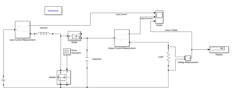
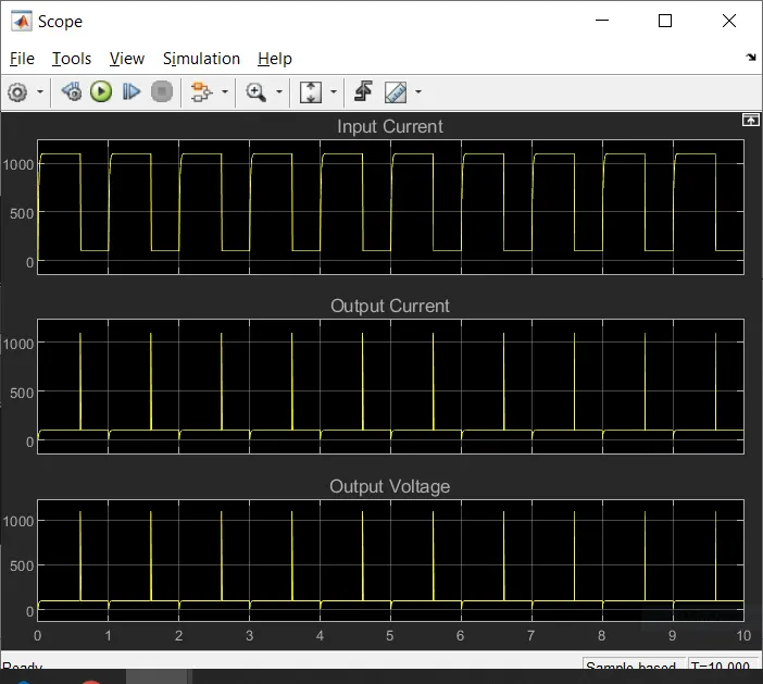
The Simulink model is developed using a DC voltage source supllied to the inductor, the power electronic switches used here is diode and MOSFET. A pulse generator block is used to provide the input signal with 60% Duty cycle. A capacitor is connected in parallel to the MOSFET and a load is also connected in parallel. Current sensors at the input and output and a voltage sensor across a load is connected to measure the current and voltage respectively. The generated output signals with respect to the input signal is plotted using scope.
The scope results are
3.Explain the difference between VFD and Vector control drive. Can we use VFD method for induction motor in EV application?
Variable Frequency Drive:
A VFD is atype of motor controller that drives an electric motor by varying the frquency and voltage supplied to the electric motor. Other names for a VFD are variable speed drive, adjustable speed drive, adjustable speed drive, adjustable frequency drive and Inverter.
Frequency is directly related to the motor's speed (RPMs). In other words, the faster the frequency, the faster the RPMs Will increase. If an application does not require an electric motor to run at full speed, the VFD can be used to rmp down the frequency and voltage to meet the requirements of the electric motor's load. As the application's motor speed requirements change, the VFD can simply turn up or down the motor speed to meet the speed requirement.
VFD for AC motors have been the innovation that has brought the use of AC motors back into prominence. The AC induction motor can have its speed changed by changing the frequency of the voltage used to power it. This menas that if the voltage applied to an AC motor is 50Hz, the motor works at its rated speed. If the frequency is increased above 50Hz, the motor will run faster than its rated speed, and if the frequency of the supply voltage is less than 50Hz, the motor will run slower than its rated speed. According to the variable frequency drive working principle, it's the electronic controller specifically designed to change the frequency of voltage supplied to the induction motor.
Vector Control Drive:
Vector control, also called field-oriented control (FOC), is a VFD control method in which the stator current of a three phase AC electric motor are identified as two orthogonal components that can be visualized with a vector. One component defines the magnetic flux of the motor, the other define the Torque. The control system of the drive calculates te corresponding current component referneces from the flux and torque references given by the drives speed control. Typically PI controllers are used to keep the measured current components at their reference values. The pulse-width modulation of the variable-frequency drive defines the transistor switching according to the stator voltage refernces that are the output of the PI current controllers.
VFD Vs VCD
All AC drives regardless of control techniques are variable frequency drives (VFD). There are various control techniques which may be applie such as
- Scalar Control (V/f)
- Vector control
- Direct torque control
- Slip control
V/f control mode: Just like driving a car, the throttle opening on your feet stays the same status, while the car speed is definitely changing because the road on which the car is running is uneven, and the road obstruction is also changing. therefore, when you go uphill, the speed will slow down while it will go when you go downhill. For the frequency converter, the frequency you set is just like the throttling opening of your car. In V/F control mode, the throttle opening is fixed.
Vector control mode:It can control the car to keep the speed constant and improve the speed control accuracy under the changes of road conditions, obstruction, uphill and downhill. Then inorder to ensure that the speed is stable and constant regardless of these changes, the throttle opening must be adjusted accordingly. At this time, the speed you set is just like the throttle opening, the set value is not changed. However does the throttle opening change and adjusted with the chnages of road conditions? Infact, when you choose Vector control. the CPU inside the drive opens this special fucntion, Utilize the feedback from the motor current change, through the internal solidified program and formula of the CPU, through the onternal PID regulator of the CPU to increase or decrease the opening degrees of throttle on the basis of your original throttle opening degree. So, in both V/F control and vector control mode, your throttle openings both have no change, but actually V/F control indeed does not chnage the throttle opening, while for the vector control, the throttle opening is actually variable, so that the speed can be kept the same as much as possible.
Your Assets
| Filname | Size | Action |
|---|---|---|
| Simplep…cuit.slx | 28.11 KB |