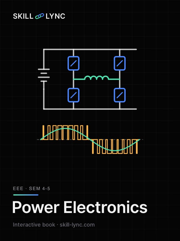
Power Electronics
Fire a thyristor, watch a rectifier's current go discontinuous, tune a buck converter and build a PWM inverter in your browser
Thirteen chapters, 13 interactives, few words. Every chapter is mapped to the Anna University, VTU, SPPU, Mumbai University and KTU units it covers: the switches (diodes, thyristors, MOSFETs, IGBTs), then the four conversions they make possible, AC to DC (rectifiers), DC to DC (choppers and buck, boost and buck-boost converters), DC to AC (inverters and PWM) and AC to AC (voltage controllers and cycloconverters), and where each one runs: motor drives, SMPS, UPS, solar and EV chargers.
- AUEE3591Power Electronics
- VTUBEE503Power Electronics
- SPPU303142Power Electronics
- MUEEC404Power Electronic Devices and Circuits
- KTUPCEET403Power Electronics and Drives
By Skill-Lync · Updated 16 Nov 2026 · 13 chapters · 13 interactives · free, no sign-up
Power semiconductor devices: the switches
Which syllabus covers thisAU EE3591 Units I and IIVTU BEE503 Modules 1 and 2SPPU 303142 Unit 2MU EEC404 Modules 2 and 6KTU PCEET403 Module I
Why do power converters use switches, not resistors?
A switch is either fully on (current flows, almost no voltage across it) or fully off (voltage across it, no current). Either way is near zero, so it wastes almost no power. A linear regulator drops the excess voltage across a transistor and burns it as heat. Power electronics controls energy by timing on and off, which is why converters reach 95–99% efficiency.
Which device does what?
Power diode: uncontrolled, conducts when forward biased. Thyristor (SCR): turned on by a gate pulse, turns off only when its current falls to zero. GTO: gate turn-off thyristor. Power BJT: current-driven, now rare. Power MOSFET: voltage-driven and fast, best below a few hundred volts. IGBT: MOSFET gate with a bipolar output, the workhorse from 600 V to several kV. SiC and GaN switch faster with lower loss.
Where does a switch lose power?
Two places. Conduction loss while on: for a MOSFET, for an IGBT. Switching loss during each transition, when voltage and current overlap: with linear ramps and an inductive load each edge costs about . Switching loss grows with frequency, so slow IGBTs suit lower frequencies and MOSFETs higher ones.
How hot does the device get?
Losses flow out as heat through a chain of thermal resistances, junction to case, case to heat sink and sink to air, like current through resistors in series. The junction must stay below its rated maximum, usually 150–175 °C for silicon. That is why a converter's heat sink is often its largest part.
How is a MOSFET or IGBT gate driven?
The gate is a capacitor: switching fast means charging it with amps for nanoseconds, so a driver IC sits between the controller and the switch. The upper switch of a leg floats, so its driver needs a bootstrap supply or isolation through a pulse transformer or opto-coupler. A dead time between the two switches of a leg prevents shoot-through.
You double the switching frequency of a MOSFET converter. Conduction loss stays the same. Switching loss:
Every cycle has one turn-on and one turn-off, each costing a fixed energy. Twice as many cycles per second means twice the switching power: .
Worked examples
MOSFET losses · 400 V, 20 A, = 50 ns, = 100 ns, = 50 kHz, = 40 mΩ, duty 0.5
- = ½ × 400 × 20 × 50 ns = 0.2 mJ; = 0.4 mJ
- = 0.6 mJ × 50,000 = 30 W
- = 8 W
Answer: Total 38 W
IGBT or MOSFET: where conduction losses cross · IGBT = 1.8 V against MOSFET = 40 mΩ
- Equal when
- = 45 A
Answer: Above 45 A the IGBT conducts with less loss; below it the MOSFET does
Junction temperature · 38 W in the device; = 0.8, = 0.2, = 1.0 °C/W; ambient 40 °C
- = 2.0 °C/W
- Rise = 38 × 2.0 = 76 °C
Answer: = 116 °C, within a 150 °C rating
Thyristors: firing, protection and commutation
Which syllabus covers thisAU EE3591 Unit IVVTU BEE503 Module 3SPPU 303142 Unit 1MU EEC404 Modules 1 and 6KTU PCEET403 Module I
What does the SCR's characteristic show?
Reverse biased, it blocks like a diode. Forward biased with no gate current it also blocks, until the voltage reaches the forward breakover voltage. A gate current lowers the breakover point, so a small pulse fires it at normal voltages. Once on, it drops about 1–2 V and stays on as long as the anode current stays above the holding current.
Why does the SCR latch?
Split its four layers p-n-p-n into two interlocked transistors, p-n-p and n-p-n. Each one's collector current is the other's base current. When the sum of their current gains approaches 1, the loop feeds itself and the anode current is limited only by the external circuit. The gate just starts the loop.
How is an SCR turned on?
Gate triggering is the normal way: a DC signal, a pulse, or a pulse train through a pulse transformer or opto-isolator. Other ways are unwanted: forward voltage above breakover, a fast charging the junction capacitance, heat, or light (used deliberately in light-triggered SCRs for HVDC). Firing circuits: R, RC, and the UJT relaxation oscillator.
What protects a thyristor?
An RC snubber across it limits so it does not fire by itself; a small series inductor limits at turn-on, before the current spreads across the junction. Fast fuses ( rating below the device's) clear faults, and an MOV or RC network clamps voltage spikes. Heat sinks keep the junction cool.
How is a conducting thyristor turned off?
Its current must fall to zero and stay reverse biased for longer than the turn-off time . In AC circuits the supply does it: natural or line commutation. In DC circuits a forced commutation circuit does it: class A (self, resonant load), B (resonant LC), C (complementary, a second SCR and capacitor), D (auxiliary SCR), E (external pulse), F is line commutation.
How are thyristors used in series and parallel?
When one device's rating is not enough, strings are used: in series for voltage (HVDC valves have dozens), in parallel for current. Devices never share equally, so series strings get static equalising resistors and dynamic RC networks, and parallel ones get matched devices or small series inductors. String efficiency says how well the devices are used.
An SCR is fired with a gate pulse but the load current only reaches a value between its holding and latching currents before the pulse ends. The SCR:
To stay on after the gate is removed, the anode current must first reach the latching current . The lower holding current only applies once it has latched. Try it in the interactive: set the gate to 'removed' after firing.
Worked examples
Two-transistor model · = 0.45, = 0.5, = 20 mA, leakage negligible
Answer: = 0.2 A; as it runs away
UJT firing oscillator · = 10 kΩ, = 0.1 µF, intrinsic stand-off ratio = 0.63
- = 0.994 ms
Answer: ≈ 1006 Hz
Snubber and di/dt inductor · 300 V supply, 50 µH circuit inductance, limit 50 V/µs, limit 50 A/µs, damping ratio 0.65
- = 50 × 10⁶ × 50 × 10⁻⁶ / 300 = 8.33 Ω
- = 1.22 µF
- = 6 µH
Answer: ≈ 8.3 Ω, ≈ 1.2 µF; the 50 µH already limits to 6 A/µs
String efficiency · A 6 kV valve built from four 1.8 kV thyristors in series
Answer: 83.3%: the derating covers unequal sharing
Diode rectifiers and capacitor filters
Which syllabus covers thisAU EE3591 Unit IIIVTU BEE503 Module 1SPPU not in syllabusMU not in syllabusKTU not in syllabus
What do half-wave and full-wave diode rectifiers give?
A half-wave rectifier passes one half-cycle: average , with large ripple and DC in the transformer. A full-wave rectifier, centre-tapped (two diodes) or bridge (four), passes both: average . The bridge needs no centre tap and each diode blocks only , so it is the usual choice.
What does a capacitor filter do?
It charges to the peak and then feeds the load between peaks, so the output sits near with a small sawtooth ripple. The catch is the input current: the diodes conduct only in short, tall pulses near each peak, so the power factor drops to about 0.5–0.7 with heavy harmonics. LC filters and active PFC fix that.
What are voltage doublers and three-phase diode bridges?
A voltage doubler charges two capacitors on alternate half-cycles and stacks them, giving about at light load; it lets one supply serve 115 V and 230 V mains. The three-phase diode bridge is the front end of most drives: six pulses per cycle, average 1.35 times the line voltage and only about 4% ripple.
How do you judge a rectifier?
By its performance factors: efficiency (DC power over AC power), form factor and ripple factor of the output, transformer utilisation factor (DC power over the transformer's VA), peak inverse voltage on each diode, and on the input side the distortion factor and power factor. Power quality standards now matter as much as the output.
You add a large capacitor across the output of a diode bridge. The input power factor:
The diodes now conduct only while the supply is above the capacitor voltage, a short pulse at each peak. The current becomes tall and narrow: rich in harmonics, low distortion factor, power factor around 0.6.
Worked examples
Bridge rectifier, resistive load · 230 V, 50 Hz, R = 100 Ω
- = 207.1 V, = 2.07 A
- = 230 V, so ripple factor = √((230/207.1)² − 1) = 0.483
- PIV per diode = = 325.3 V
Answer: 207.1 V, ripple factor 0.483 (half-wave: 103.5 V, ripple factor 1.21)
Capacitor filter · Same bridge, C = 1000 µF, R = 100 Ω
- = 32.5 V peak to peak
- = 309 V
Answer: About 309 V with 33 V ripple, against 207 V unfiltered
Three-phase diode bridge and a voltage doubler · 415 V three-phase; and a doubler on 230 V
- = 1.35 × 415 = 560.4 V; PIV = √2 × 415 = 586.9 V
- Doubler, no load:
Answer: 560 V DC link; doubler about 650 V
Single-phase controlled rectifiers
Which syllabus covers thisAU EE3591 Unit IVVTU BEE503 Module 4SPPU 303142 Unit 3MU EEC404 Module 3KTU PCEET403 Module II
How does a controlled rectifier set its output voltage?
By delaying the firing of the thyristors by a firing angle after the point where they would start to conduct as diodes. The later the firing, the less of each half-cycle reaches the load. With a resistive load the current follows the voltage and stops at the zero crossing.
What changes with an inductive load?
The inductor keeps current flowing after the supply voltage reverses, so the output goes negative for a while and the thyristor turns off later, at the extinction angle . With enough inductance a full converter conducts continuously and its output depends only on . Change the load in the interactive and watch the current go continuous.
What does a freewheeling diode do?
It gives the load current a path when the output would go negative, so the output is clamped at zero instead. The thyristor turns off at the zero crossing, the average output rises, the input power factor improves and the current is smoother. A semiconverter (two thyristors, two diodes) freewheels through its own diodes.
What about a battery or motor load?
A back EMF means a thyristor can only conduct while the supply exceeds . It cannot fire before , so firing circuits use a pulse train. Charging current flows only in short pulses unless the inductance is large. The full converter can also run with , negative , feeding energy back from the load: inversion.
A full converter feeds a highly inductive load at α = 120°. The average output voltage is:
With continuous current < 0. Current still flows the same way, so power flows from the DC side back to the AC supply. This needs a source on the DC side, like a motor being braked.
Worked examples
Half-wave, resistive load · 230 V, 50 Hz, α = 60°, R = 10 Ω
- = 325.3 V
- = 77.65 V
- = 145.9 V
Answer: = 77.7 V, = 7.77 A, = 145.9 V
Half-wave, RL load: extinction angle · Same supply, α = 60°, R = 10 Ω, L = 50 mH
- = 57.52°
- Solve : = 237.2°
- = 53.9 V
Answer: Conducts for 177°, = 53.9 V (lower than the 77.7 V with R only)
Full converter and semiconverter · 230 V, highly inductive load, α = 45°
- Full: = 146.4 V; input PF = = 0.637
- Semi: = 176.7 V
Answer: 146.4 V (full) vs 176.7 V (semi): freewheeling removes the negative part
Three-phase converters and source inductance
Which syllabus covers thisAU EE3591 Unit IVVTU BEE503 Module 4SPPU 303142 Unit 4MU EEC404 Module 3KTU PCEET403 Module II
How does a three-phase bridge work?
Six thyristors: the top group connects the most positive phase to the positive rail, the bottom group the most negative phase to the negative rail. They fire in order 1-2-3-4-5-6, 60° apart, each conducting 120°. The output is six line-voltage pulses per cycle, so ripple is small. is counted from the natural commutation point, 30° after the phase voltage zero.
What about the half-wave and semiconverter versions?
A three-pulse (half-wave) converter uses three thyristors and the neutral: half the output, larger ripple and DC current in the transformer. A three-phase semiconverter replaces the bottom group with diodes: the output cannot go negative, so no inversion, but the power factor is better at large .
What does source inductance do?
Current cannot jump from one phase to the next through a real transformer's leakage inductance. For an overlap angle two thyristors conduct together and the output sits halfway between the two phases. That notch costs output voltage in proportion to load current, like an internal resistance that dissipates nothing.
When does a converter feed power back?
With between 90° and 180° and a DC source pushing current, is negative and power flows to the AC grid: line-commutated inverter mode, used in regenerative braking and HVDC. The thyristor must be reverse biased for longer than its turn-off time after overlap ends, so is limited to about 150–165°.
Load current on a three-phase converter doubles. With source inductance, the overlap angle:
More current takes longer to transfer through the same leakage inductance: is proportional to , and the voltage drop doubles.
Worked examples
Ideal six-pulse converter · 415 V line, 50 Hz, α = 30°, = 50 A (ripple-free)
- = 560.4 V
- = 485.4 V
Answer: = 485.4 V, = 24.3 kW
With 2 mH source inductance · Same, = 2 mH per phase
- = 0.6283 Ω; drop = = 30.0 V
- = 0.7590
- = 10.63°
Answer: = 455.4 V, overlap 10.6°
Inverter mode and the extinction margin · α = 150°, same and , thyristor = 100 µs
- = -515.4 V (power returned)
- : = 16.68°
- = 13.32°; = 1.8°
Answer: 25.8 kW fed back; margin 13.3° is safe, but overlap grew from 10.6° to 16.7°
Input power factor, harmonics and dual converters
Which syllabus covers thisAU EE3591 Units III and IVVTU BEE503 Module 4SPPU 303142 Unit 3MU EEC404 Module 3KTU PCEET403 Module III
Why is a rectifier's power factor not just cos φ?
Its input current is not a sine wave. Only the fundamental carries average power, so power factor has two parts: the displacement factor, of the angle between voltage and fundamental current, and the distortion factor, how much of the rms current is fundamental. For a thyristor converter the displacement angle is roughly .
Which harmonics appear?
A -pulse converter draws harmonics of order with magnitude about . A single-phase bridge (square current) has 3, 5, 7, 9...; a six-pulse bridge has 5, 7, 11, 13... Twelve-pulse converters (two bridges on star and delta windings) cancel the 5th and 7th. Harmonics heat transformers and distort the grid, so IEEE 519 and IEC 61000-3 limit them.
How is the power factor improved?
Freewheeling (semiconverters) cuts the reactive current at large . Extinction-angle, symmetrical-angle and PWM control shift or shape the current pulses. Sequence control of two converters in series helps at low output. Modern chargers and drives use an active PFC boost stage that makes the input current a sine wave in phase with the voltage.
What is a dual converter?
Two full converters connected back to back across the load: one carries positive current, the other negative, so together they work in all four quadrants, as for a reversing DC drive. Their firing angles keep so the average voltages match. They run either with circulating current through a reactor, or without it, one converter blocked at a time.
A single-phase full converter carries a constant 10 A DC load current at α = 0. Its input power factor is:
At α = 0 the current is in phase (displacement factor 1), but it is a square wave whose fundamental is = 0.9 of its rms. Power factor = 0.9 × 1.
Worked examples
Single-phase full converter · = 10 A, α = 30°
- = 10 A (square wave), = 9.00 A
- DF = cos 30° = 0.866; distortion factor = 0.900
- THD = = 48.3%
Answer: PF = 0.780
Three-phase bridge · = 10 A, α = 30°
- = 8.165 A (120° blocks), = 7.797 A
- PF = = 0.827
- THD = 31.1%; 5th = 1.56 A, 7th = 1.11 A
Answer: PF = 0.827, THD 31.1% (vs 48.3% single-phase)
Semiconverter at α = 60° · = 10 A
- = 8.165 A
- = 7.797 A
- DF = cos(α/2) = cos 30°
Answer: PF = 0.827; a full converter at 60° gives only 0.450
Dual converter firing angles · 230 V supply, converter 1 at α₁ = 60°
- α₂ = 180° − 60° = 120°
- : 103.5 V at 60°, −103.5 V at 120° across reversed terminals
Answer: Both give 103.5 V at the load
DC-DC converters: buck, boost and buck-boost
Which syllabus covers thisAU EE3591 Unit IVTU BEE503 Module 5SPPU 303142 Unit 2MU EEC404 Module 5KTU PCEET403 Module II
How do you find a converter's output voltage?
In steady state the inductor's average voltage is zero: its current rises by the same amount while the switch is on as it falls while off. Write that volt-second balance and the conversion ratio falls out. The same trick on the capacitor (charge balance) gives the currents.
How big are the ripples?
Inductor ripple is the volt-seconds divided by . In a buck, the capacitor absorbs only the ripple current, so its voltage ripple is small and falls with . In a boost or buck-boost, the output capacitor alone feeds the load while the switch is on, so ripple is much larger. Real capacitors add an ESR term.
What is discontinuous conduction mode?
At light load or small the inductor current falls to zero before the next switching cycle. The conversion ratio then depends on load as well as , rising above the CCM value. The boundary is the critical inductance: below it the converter is in DCM. Designs choose for CCM at the minimum load, or deliberately run in DCM.
What do real converters add?
Switch and diode drops, inductor resistance and ESR reduce efficiency and cap the boost gain: a real boost converter's gain peaks and then falls as . The Ćuk and SEPIC converters give buck-boost ratios with non-pulsating input current; synchronous rectification replaces the diode with a MOSFET to cut losses at low voltage.
A buck converter's inductor is halved, everything else the same, still in CCM. The output voltage:
In CCM regardless of . Only the ripple changes: . Halve it again and it may slip into DCM, where does rise.
Worked examples
Buck converter · 24 V in, D = 0.4, L = 100 µH, C = 100 µF, 50 kHz, R = 10 Ω
- = 0.4 × 24 = 9.6 V, = 0.96 A
- = 1.152 A
- = 28.8 mV
- = 60 µH
Answer: 9.6 V, ripple 1.15 A and 28.8 mV; CCM since 100 > 60 µH
Boost converter · Same parts, boost, D = 0.4
- = 24/0.6 = 40 V; = 40²/(10 × 24) = 6.67 A
- = 1.92 A
- = 0.32 V
Answer: 40 V with 0.32 V ripple: 11 times the buck's, from the pulsed diode current
Buck-boost in DCM · 24 V, D = 0.4, R = 10 Ω, 50 kHz, but L = 5 µH
- = 0.05 < = 0.36: DCM
- = 24 × 0.4 / √0.05 = 42.9 V
Answer: 42.9 V, not the CCM value of 16 V: in DCM the ratio depends on the load
Choppers and DC motor drives
Which syllabus covers thisAU not in syllabusVTU BEE503 Module 5SPPU 303142 Units 2 and 3MU not in syllabusKTU PCEET403 Module IV
How does a chopper control voltage?
It connects the DC source to the load for out of every period . Constant-frequency control (PWM) varies at fixed ; variable-frequency control varies , which makes filtering harder. A step-up chopper uses the motor's inductance to push energy back into a higher-voltage supply: regenerative braking in trains and EVs.
What are chopper classes A to E?
They differ in which signs of load voltage and current they allow. Class A: positive V and I only (first quadrant, motoring). Class B: positive V, negative I (regeneration). Class C: two quadrants, I reverses. Class D: two quadrants, V reverses. Class E: four quadrants, a full H-bridge. Pick a source in the interactive and see which quadrants it can reach.
How does a converter control a DC motor's speed?
A separately excited motor's speed rises with armature voltage and falls slightly with load: . The torque sets the current, . So a converter that sets sets the speed, and its current limit sets the torque. Field weakening gives speed above base speed.
Which converter for which drive?
Single-phase semi and full converters for small drives; three-phase bridges above a few kW. A full converter adds inversion: with an overhauling load the motor runs backwards and the bridge feeds power to the mains. Dual converters and class E choppers give full four-quadrant reversing drives; EVs use the inverter equivalent.
A DC motor on a class A chopper is going downhill and the load starts driving the motor. The chopper can:
Class A conducts current one way only (first quadrant). Regenerative braking needs reversed current at positive voltage: class B, C or E.
Worked examples
Converter-fed DC motor · 230 V single-phase full converter, α = 30°, = 0.5 Ω, = 1.2 V·s/rad, load 20 N·m, continuous current
- = 179.3 V
- = 16.67 A
- = 142.5 rad/s
Answer: 1361 rpm
Regenerative braking with an overhauling load · Same motor, α = 120°, the load holds 20 N·m
- = -103.5 V
- = -93.2 rad/s (reversed)
- Power to the mains = 103.5 × 16.67 = 1726 W
Answer: Runs at 890 rpm in reverse, quadrant 4, returning 1.73 kW
Chopper-fed DC motor · 220 V DC, 1 kHz chopper, D = 0.7, same motor and load
- = 0.7 ms of every 1 ms
- = 0.7 × 220 = 154 V
- = 121.4 rad/s
Answer: 1159 rpm
Single-phase inverters
Which syllabus covers thisAU EE3591 Unit IIVTU BEE503 Module 5SPPU 303142 Unit 5MU EEC404 Module 4KTU PCEET403 Module III
How does an inverter make AC from DC?
A half bridge connects the load alternately to the top and bottom of a split DC supply: . A full bridge (H-bridge) flips the whole across the load with two diagonal pairs of switches. Each switch has an antiparallel diode, so an inductive load's current always has a path back to the supply.
What is wrong with a square wave?
It contains every odd harmonic at of the fundamental: 33% third, 20% fifth. Its THD is 48%. Motors heat up and hum; transformers and filters must be larger. Shaping the pulse helps: a quasi-square wave of width 120° removes the third harmonic completely, at the cost of a lower fundamental.
What current does an RL load draw?
Each harmonic voltage drives a current through its own impedance , so inductance filters the higher ones and the current looks much more sinusoidal than the voltage. Just after each switching, current still flows the old way through the diodes, returning energy to the DC link.
What is the difference between a VSI and a CSI?
A voltage source inverter has a stiff DC voltage (a large capacitor) and switches it into a voltage waveform; the load decides the current. A current source inverter has a stiff DC current (a large inductor) and switches it into a current waveform. CSIs survive short circuits and use thyristors in large drives; VSIs dominate everywhere else.
A square-wave inverter feeds an inductive load. Compared with the voltage, the load current is:
The th harmonic current is : inductance suppresses the higher harmonics, so the current is a series of exponential arcs close to a sine wave.
Worked examples
Square-wave full bridge · = 200 V, 50 Hz
- = 180.1 V rms
- = 60.0 V, = 36.0 V
- THD = = 48.3%
Answer: = 200 V rms, = 180.1 V, THD 48.3%
RL load current · R = 10 Ω, L = 30 mH, same inverter
- = √(10² + 9.42²) = 13.74 Ω, so = 180.1/13.74 = 13.10 A
- τ = 3 ms, T/2 = 10 ms: peak = 20 (1 − e^−3.33)/(1 + e^−3.33) = 18.62 A
Answer: Fundamental 13.1 A rms, peak 18.6 A
Quasi-square wave without a third harmonic · 200 V, pulse width 2d = 120°
- = 0
- = (4 × 200/π) sin 60° / √2 = 155.9 V
- = 163.3 V
Answer: No 3rd harmonic; fundamental 155.9 V instead of 180.1 V
PWM techniques: single pulse to space vector
Which syllabus covers thisAU EE3591 Unit IIVTU BEE503 Module 5SPPU 303142 Units 5 and 6MU EEC404 Module 4KTU PCEET403 Module III
Why chop the output into many pulses?
To control the voltage inside the inverter and push harmonics to high frequencies, where the load's inductance blocks them cheaply. Single-pulse modulation varies one pulse per half-cycle (high low-order harmonics); multiple-pulse uses several equal pulses; sinusoidal PWM sets each pulse width by a sine reference.
How does sinusoidal PWM work?
Compare a sine reference with a triangular carrier: the switch is on while the reference is above the carrier. The amplitude ratio sets the fundamental, linearly up to ; the frequency ratio sets where harmonics sit, around and its multiples. Bipolar switching gives ; unipolar adds a zero level and moves the first sidebands to .
What happens above m_a = 1?
Overmodulation: the reference exceeds the carrier peak, some pulses merge and the output moves towards a square wave. The fundamental still rises, but no longer in proportion to , and low-order harmonics return. The ceiling is the square wave's times .
What do space vector PWM and harmonic elimination add?
Space vector PWM treats the three-phase inverter's eight switch states as vectors and averages the two nearest active vectors plus a zero vector each period. It uses the DC link 15.5% better than sine PWM in the linear range and is standard in drives. Selective harmonic elimination solves for notch angles that cancel chosen harmonics, such as the 5th and 7th.
In unipolar SPWM with m_f = 15, the first group of harmonics appears around:
The two legs switch against the same carrier with opposite references; their harmonics at cancel in the line-to-line output, leaving sidebands around = 30 (29 and 31).
Worked examples
Bipolar SPWM · = 200 V, = 0.8, = 15, 50 Hz
- = 160 V, rms 113.1 V
- Harmonics at 15 (0.818 × 200 = 163.6 V peak) and at 13, 17 (0.22 × 200 = 44 V)
- Switching frequency 15 × 50 = 750 Hz
Answer: 113.1 V rms fundamental; the largest harmonic sits at 750 Hz, easy to filter
Three-phase sine PWM vs SVPWM · 600 V DC link, = 0.8
- = 0.612 × 0.8 × 600 = 293.9 V rms
- SVPWM linear limit: = 424.3 V rms, vs 367.2 V for sine PWM
Answer: 294 V line; SVPWM reaches 15.5% more before overmodulating
Single-pulse width for 100 V · Full bridge, = 200 V, want = 100 V rms
- = 0.5554
- = 33.74°
Answer: Pulse width 2d = 67.5°
Three-phase inverters: 180° and 120° conduction
Which syllabus covers thisAU EE3591 Unit IIVTU BEE503 Module 5SPPU 303142 Unit 6MU EEC404 Module 4KTU PCEET403 Modules III and IV
How does a six-step inverter work?
Three legs, six switches, fired every 60° in order S1 to S6. In 180° conduction each switch is on for half a cycle, three switches conduct at a time, and the star phase voltage steps through and . Step through the six intervals in the interactive and watch which switches conduct.
What changes in 120° conduction?
Each switch is on for 120°, so only two conduct at any time and one phase floats. A 60° gap between the top and bottom switch of a leg means no shoot-through risk, but the floating phase's voltage depends on the load and the output is lower. 180° conduction needs a short dead time between the two switches of a leg.
Which harmonics are in a six-step output?
No even harmonics and no triplen harmonics (3rd, 9th...) in the line voltages: they are equal in all three phases and cancel. What remains are the 5th, 7th, 11th, 13th at of the fundamental, the same family as a six-pulse rectifier. Line THD is 31%.
Where are three-phase inverters used?
Variable-frequency drives for induction and permanent-magnet motors (keeping V/f constant), EV traction inverters (400 or 800 V battery, SVPWM at 10–20 kHz), solar and battery grid-tie inverters, and UPS outputs. Multilevel inverters (diode-clamped, flying capacitor, cascaded H-bridge) stack levels for medium voltage.
Switching a six-step inverter from 180° to 120° conduction at the same DC voltage makes the output voltage:
Only two switches conduct at a time and each phase floats for a third of the cycle: line rms falls from to .
Worked examples
180° conduction into a star R load · = 600 V, R = 10 Ω per phase
- Phase: (√2/3) × 600 = 282.8 V; line 489.9 V
- Fundamental line voltage = = 467.8 V
- = 24.0 kW
Answer: 282.8 V phase, 489.9 V line, 24 kW
120° conduction, same load · = 600 V, R = 10 Ω
- Phase: 600/√6 = 244.9 V; line: 600/√2 = 424.3 V
- = 18 kW
Answer: 18 kW, 25% less than 180° mode
AC-AC converters: voltage controllers, TRIACs and cycloconverters
Which syllabus covers thisAU EE3591 Unit VVTU BEE503 Module 4SPPU 303142 Units 1 and 4MU not in syllabusKTU PCEET403 Module II
How does an AC voltage controller work?
Two thyristors back to back (or one TRIAC) in series with the load, each fired at in its half-cycle. The output is chopped sine waves of the supply frequency: the rms voltage falls as rises. Light dimmers, fan regulators, heaters and soft starters for induction motors work this way.
What happens with an inductive load?
Current continues past the voltage zero until the extinction angle . If is less than the load angle , current never stops and the output is the full sine: no control. So the control range is , and the firing needs a pulse train or long pulses. Move below in the interactive to see control lost.
What is integral cycle control?
Switch the load fully on for whole cycles, then off for , always at voltage zero. No partial sine waves means low harmonics and no switching noise, but the power arrives in bursts. It suits loads with long time constants, like furnaces and heaters, not lamps or motors.
What about three-phase controllers?
Three pairs of thyristors, one per line, control star or delta loads; the conduction pattern changes with (three or two thyristors on). They soft-start induction motors by ramping the voltage, cutting starting current from 6–8 times rated to about 2–4 times. Sequence control of transformer taps gives smoother regulation.
How does a TRIAC differ from two SCRs?
A TRIAC is one bidirectional thyristor with a single gate, fired by positive or negative gate current in either half-cycle: four triggering modes, most sensitive in I+ and III−. A DIAC in an RC network gives it a symmetrical trigger, the classic light dimmer and fan regulator. It suits mains loads of up to tens of amps; larger loads use antiparallel SCRs.
How does a cycloconverter change frequency?
It builds a lower-frequency output directly from pieces of the supply, with no DC link. A positive group of thyristors supplies the load for the positive half of the output, a negative group for the negative half. A single-phase step-down cycloconverter gives by letting each group conduct for supply half-cycles.
Where are three-phase cycloconverters and matrix converters used?
Each output phase of a three-phase cycloconverter is a dual converter whose firing angle varies sinusoidally, so its average output traces a sine wave up to about a third of the supply frequency: cement and ball mills, ship propulsion, rolling mills. A matrix converter's 3×3 bidirectional switches give any frequency with sinusoidal input current, but at most 0.866 voltage gain.
An AC voltage controller drives an RL load with load angle φ = 60°. Firing at α = 30° gives:
With the current of one thyristor is still flowing when the other is fired, so the load sees the full supply. Control starts only at .
Worked examples
Resistive load · 230 V, α = 60°, R = 10 Ω
- = 230 √((π − π/3 + ½ sin 120°)/π) = 206.3 V
- = 4256 W
- PF = = 0.897
Answer: 206.3 V, 4256 W, PF 0.897
RL load extinction angle · |Z| = 10 Ω, φ = 45° (R = X = 7.07 Ω), α = 90°
- Solve (radians, = 1): = 220.9°
Answer: Each thyristor conducts 130.9° (less than 180°, so the controller is in control)
Integral cycle control · 230 V, R = 10 Ω, on 3 cycles, off 2
- = 178.2 V
- = 3174 W
Answer: 178.2 V, 3174 W, PF 0.775
Single-phase step-down cycloconverter · 230 V, 50 Hz, each group conducts 3 half-cycles, α = 30°, R load
- = 50/3 = 16.67 Hz
- = 230 √((π − π/6 + ½ sin 60°)/π) = 226.7 V
Answer: 16.67 Hz at 226.7 V rms
Applications: SMPS, UPS, solar MPPT and EV charging
Which syllabus covers thisAU EE3591 Unit IVTU BEE503 Module 1SPPU 303142 Unit 5MU EEC404 Module 5KTU PCEET403 Module III
How does a switched-mode power supply work?
It rectifies the mains, then a high-frequency DC-DC converter with a small transformer gives isolation and the output voltage. The flyback (an isolated buck-boost, stores energy in the transformer) suits up to about 150 W: phone chargers, adapters. The forward converter (an isolated buck) needs a reset winding; push-pull, half and full bridges handle more power.
What are online and offline UPS?
An offline (standby) UPS feeds the load from mains and switches to its battery inverter when mains fails, with a short break. An online (double-conversion) UPS always rectifies to DC, charges the battery and inverts back, so the load never sees a break or mains disturbances. Line-interactive types sit in between.
Why do high-frequency supplies use resonant converters?
Hard switching loses energy at every edge, so losses limit how high the frequency, and how small the magnetics, can go. A resonant tank (series, parallel or LLC) makes the switch voltage or current pass through zero at each transition: zero-voltage or zero-current switching. That lets server, telecom and EV charger supplies run at hundreds of kHz with high efficiency.
What is maximum power point tracking?
A solar panel's power peaks at one voltage, the maximum power point, which moves with sunlight and temperature. An MPPT controller adjusts a DC-DC converter's duty cycle to hold the panel there. Perturb and observe nudges the voltage, keeps going if power rose and reverses if it fell, so it oscillates around the peak.
Where is power electronics in an electric vehicle?
The traction inverter turns battery DC into three-phase AC for the motor and runs it backwards for regenerative braking. The on-board charger is a PFC rectifier plus an isolated DC-DC stage; a DC fast charger does the same off-board at 50–350 kW. A DC-DC converter steps the 400 or 800 V pack down to 12 V for the lights and electronics.
Clouds cut the sunlight on a panel from 1000 to 600 W/m². Its maximum power point voltage:
Short-circuit current is proportional to irradiance, but open-circuit voltage only falls with its logarithm. So the MPP current drops by about 40% while the MPP voltage moves by about a volt. Try it in the interactive.
Worked examples
Flyback turns ratio · 300 V DC in (rectified mains), 12 V out, D = 0.4
- = 12 × 0.6 / (300 × 0.4) = 0.06
Answer: ≈ 16.7 : 1
Forward converter · 48 V in, = 0.5, D = 0.4
- With an equal reset winding, D must stay below 0.5
Answer: 9.6 V
MPPT boost duty · 60-cell module (single-diode model, = 9 A, = 37.5 V, 25 °C, 1000 W/m²) into a 48 V bus
- Maximum power at = 31.8 V, = 270 W
- Boost: = 0.337
Answer: D ≈ 0.34; the controller trims it as conditions change
UPS battery size · 1 kVA load at PF 0.8 for 30 min, 48 V battery, inverter efficiency 90%
- Load = 800 W
- Energy = 800 × 0.5/0.9 = 444 Wh
Answer: 9.3 Ah at 48 V, before depth-of-discharge margin
Keep going
- GATE EE Power Electronics: devices, rectifiers and power factor, solved previous-year questions
- GATE EE Power Electronics: choppers, DC-DC converters and inverters, solved
- Fundamentals of DC-DC Converters course
- AC-DC Rectifiers and Harmonics using MATLAB course
- PG Program in Electric Vehicle Design and Development
- Buck converter calculator: inductor, capacitor and ripple
- Digital Electronics interactive book
- Electric Vehicles interactive book
- All Skill-Lync interactive books
Recommended reading
- Power Electronics: Circuits, Devices and Applications, M. H. Rashid
- Power Electronics: Converters, Applications and Design, N. Mohan, T. M. Undeland and W. P. Robbins
- Power Electronics, P. S. Bimbhra
- Modern Power Electronics and AC Drives, B. K. Bose
- Power Electronics, M. D. Singh and K. B. Khanchandani
- Fundamentals of Power Electronics, R. W. Erickson and D. Maksimović
- Thyristorised Power Controllers, G. K. Dubey, S. R. Doradla, A. Joshi and R. M. K. Sinha
How this book was made
Chapters follow the official syllabi listed above. Every interactive's formulas and every worked-example number were checked by script. Explanations, animations and examples are original to Skill-Lync.