Moment of Inertia for Different Sections using AutoCAD
This article explains the step-by-step procedure for finding the Moment of Inertia for different sections using AutoCAD to input these values in general sections properties of STAAD.Pro or any other analyzing software.
 Navin Baskar·29 Jan 2023·3 min read
Moment of Inertia for Different Sections using AutoCAD
This article explains the step-by-step procedure for finding the Moment of Inertia for different sections using AutoCAD to input these values in general sections properties of STAAD.Pro or any other analyzing software. It is usually done to import the real geometry of the section that can’t be modelled in analysis software. In all software, a separate tool is developed to create asymmetrical /irregular sections.
What is the Moment of Inertia?
The ability of a cross-section to resist bending is referred to as the moment of inertia (I). It is usually considered in relation to a reference axis like X-X or Y-Y. It is a mathematical characteristic of a section that has to do with the distribution of a surface area around the reference axis (axis of interest). Typically, a centroidal axis serves as the reference axis
Steps to find Moments of Inertia in AutoCAD
Following are the step-by-step procedures to find a Moment of Inertia in AutoCAD:
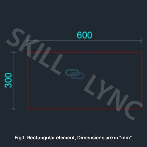
- Create a rectangle using the “REC” command with 600mm X 300mm dimensions.
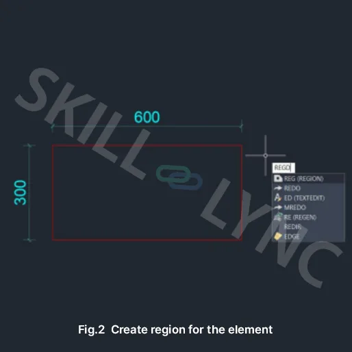
- Create a region for the rectangle using the “REG” command. After typing the command, select the object.
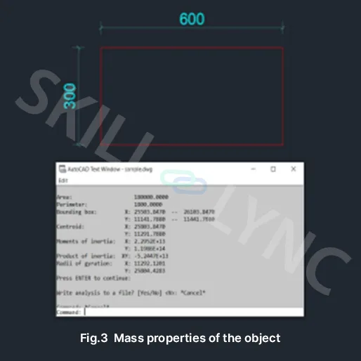
- Use the “MASSPROP” command to check the various properties of the object. Here centroid values to be noted to fix the object exactly at that position.
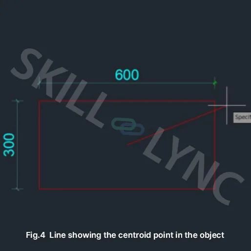
- Copy the values of the centroid and enter the centroid values of x, y to get the line in the centroid position of the object.
- With the help of that point, move the axes icon to that point to get the correct Moment of Inertiabyusing the “MASSPROP” command.
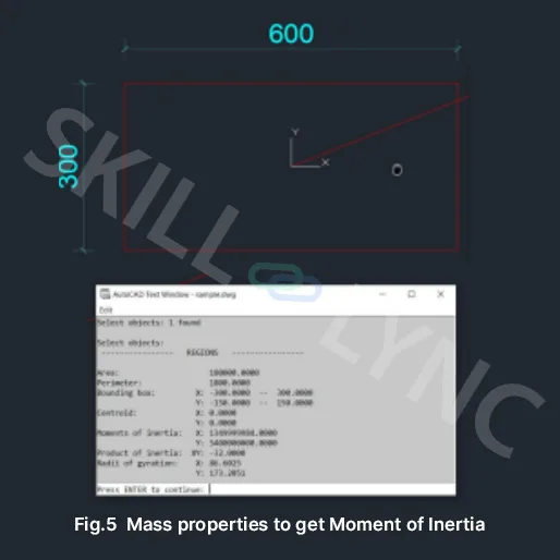
Cross checking the above term with manual calculations as follows,
Ixx = bd
3 / 12 = 600x300
3 / 12 = 1350000000 mm4
Iyy = db
3 / 12 = 300x600
3 / 12 = 5400000000 mm4
Results from manual calculation & AutoCAD-based results show the same value.
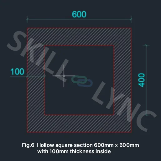
Explaining one more example with hollow Square section to compare the result of Moment of Inertia between AutoCAD & Online Moment of Inertia calculators.
- Hatches show a solid portion in the Hollow square section.
To calculate the Moment of Inertia for the hatched portion, the following steps are to be followed,
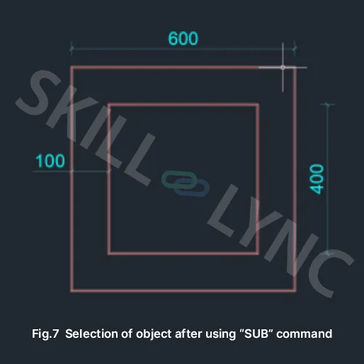
- The region of the object uses the “REG” command by selecting the whole object. ▪ After region, use the “SUB” command to subtract outer square from the inner square. Type“SUB” and press enter, select the outer square and again use the “SUB” command press enter and select an inner square. Once the procedure is done correctly, the whole object will be selected when clicking either inner or outer rectangle.
- Here trying outer object toselect, but inner object also showing selected based on “SUB” command.
- Using the “MASSPROP” command showing the Moment of Inertia of the square hollow object after making the centroid-based arrangements.
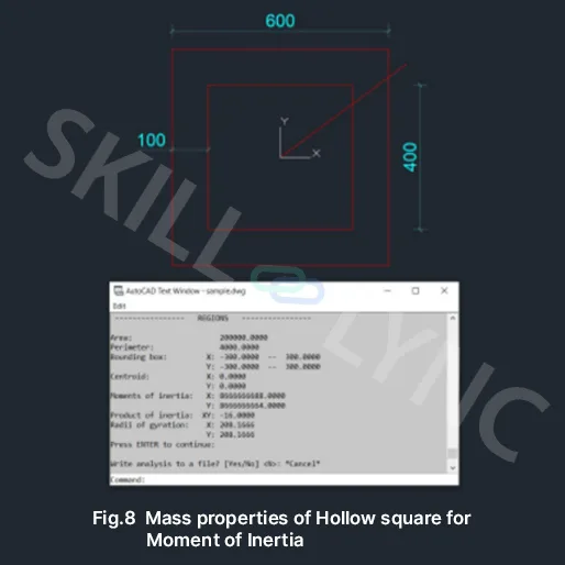
- Crosschecking the above values with the Moment of inertia online calculator.
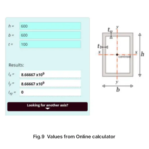
So, based on the above methods, the Moment of Inertia can be checked for analysis. Inputting the above-calculated value in Staad Pro > Properties > Definitions > General
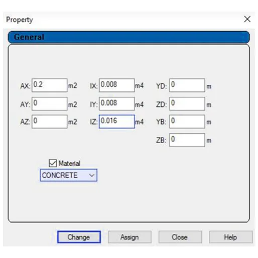
Where,
AX - Area of the section (from AutoCAD)
IX - Moment of Inertia in X direction (from AutoCAD)
IY - Moment of Inertia in Y direction (from AutoCAD)
IZ - IX + IY