Wiring harness routing & packaging Rules Week 3 Challenge
WIRING HARNESS ROUTING AND PACKAGING RULES
AIM:
The main aim of this challenge is to understand the different types of clips& clamps, backshells and corrugated tube, defining it as an electrical component from available 3D cad files by using the electrical work bench in the CATIA V5 and creating the different corrugated tubes as per given sketch for wiring harness process.
INTRODUCTION:
WIRING HARNESS:
Wiring harness is the process of systematic arrangement of all wires and cables as a single organized unit with in a bundle of insulating material. The purpose of wiring harness is to transmitting the power or electrical signals from one location to another location of device to run the operation.
In the industrial or other big applications there are many wire cables in single location for transmitting required data, in that case there need lot of cables, wires, connectors and other electrical devices. If we cannot provide proper arrangement for the wiring cable it causes the damage and hazard to the users.so that all the cables drawn through the single insulating bundle and bound together by ties, straps, cable lacing, electrical tapes etc.
CLIPS & CLAMPS:
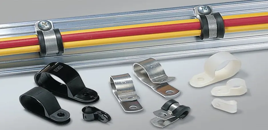
Clips are the supporting and holding elements used in the wiring harness process, it is not functioning component, only holding or fixing the cables, hoses , pipes and cable harness against the automotive bodies or surface during assembly and installations. The clamps and clips are holding the wiring harness temporarily and permanently based on the situation.it can be adjustable fixing of cable harness to easy hold and removing.
In the automotive applications the P clamp is mostly used in the practice and also stick clamp.it can hold the harness inside the clamp together in the require surface.
Design procedure:
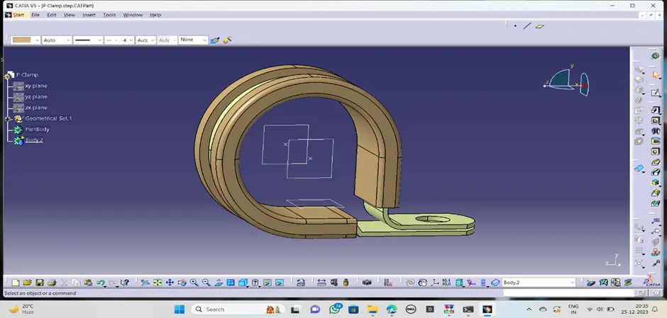
- · First create the mechanical geometrical properties to the p clamp like point, planes.
- · Create the points both sides of the clamp in center
- · Create the entry plane at one side with reference to the first point
· · Create the exit plane other side with reference to the exit point provided to it.
· Create base plane with respect to the available base surface.
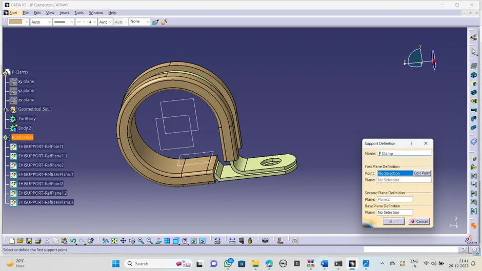
Now switched into the electrical work bench:
· Define it as a support in electrical work bench by selecting suitable definition parameters
Catalog creation:
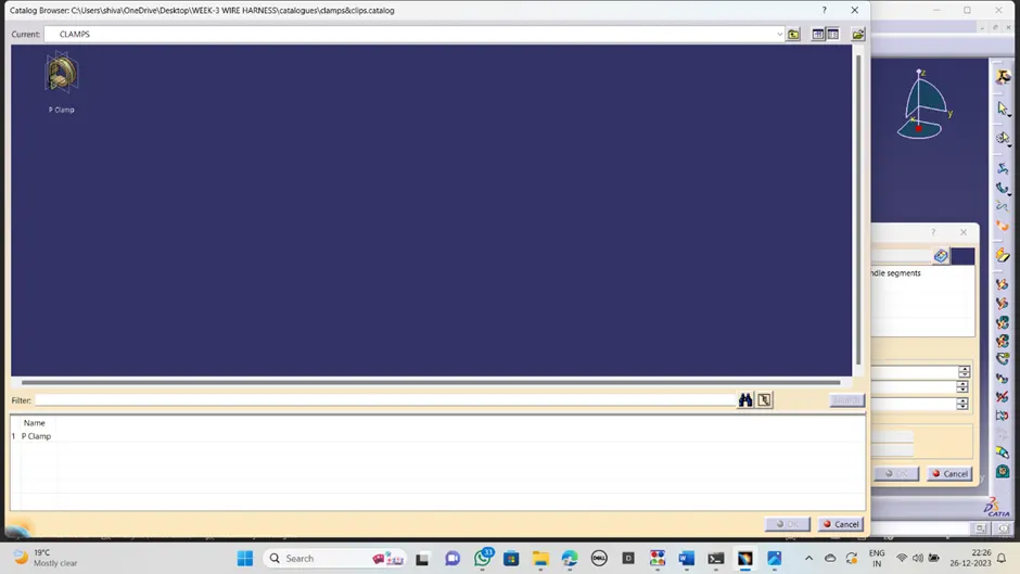
· save the all created p clamp
· created the new catalog named with p clamp, add it to part family and save it.
· Now in the same work bench available store device ,click it add part family and type.
· Save it ,now all the p clamp saved into the catalogue.
BACK SHELLS:
Back shell is the casing device with the threaded into one end of an electrical connector and provides the strain reliefs, secure and protective covering to the connector. This back shell surrounded over the connector and some cases it has provide threaded section to fit into connector end to avoid the damages from external forces.it can offering the resistance to environmental condition, wears etc.
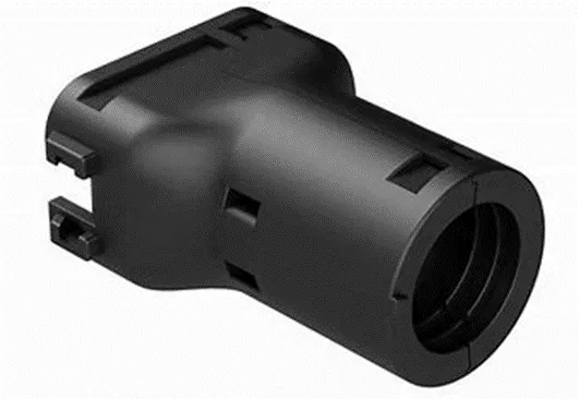
DESIGN PROCEDURE:
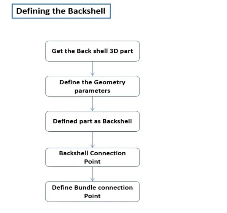
First create the mechanical geometrical parameters like;
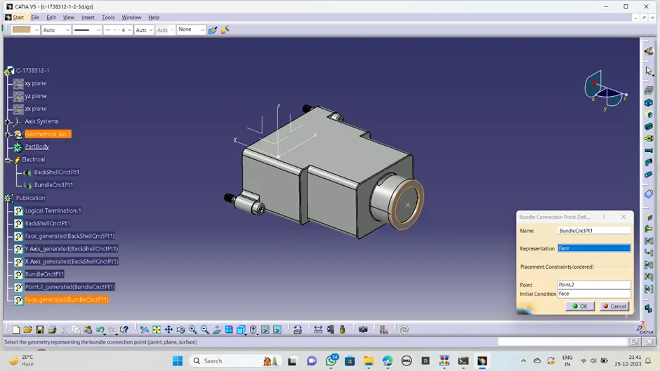
· ·Create the point for back shell connection point where the back shell entry present
· · Create the bundle connection point other side where the bundle entry is provided
· · Create the axis system for bundle connection point with suitable orientation of axis
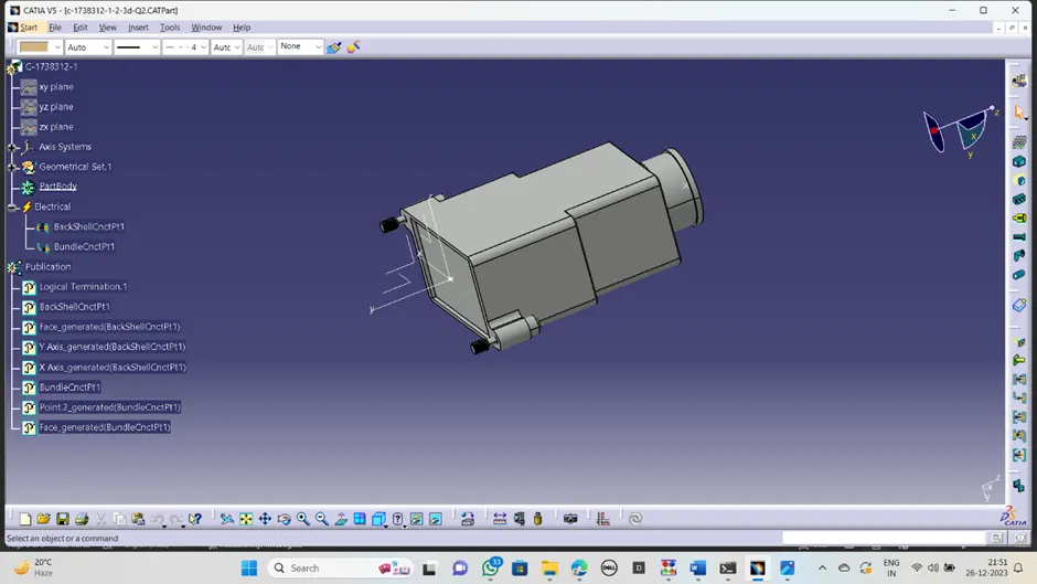
Now switched into the ELECTRICAL PART DESIGN;
· Defined this component as a electrical back shell
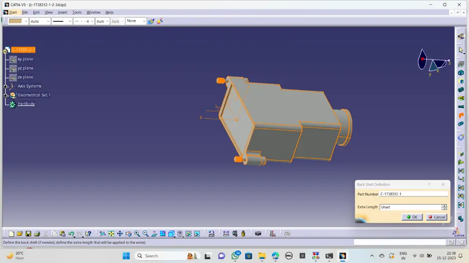
· Create the back shell connection point by selecting the point, coincidence, contact and orientation of axis
· Create the bundle connection point similar as back shell connection point in the bundle entry side
Cataloge:
· save the all created back shell
· created the new catalog named with back shell , add it to part family and save it.
· Now in the same work bench available store device ,click it add part family and type.
· Save it ,now all the back shell saved into the catalogue.
CORRUGATED TUBES:
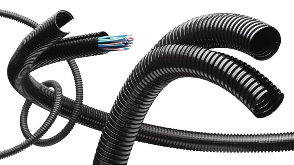
Corrugated tubes are the tube-like structure component used in the wiring harness and it is also called as conduit. The primary function of this tubes is protecting and covering the wires, cables and hoses. These tubes are very flexible to bend to very extremity, also give go protection against the high temperatures, crashing of the wires and abrasions.
These tubes are available in different sizes needed to the based-on application, it can install and remove easily.
DESIGN POCEDUR:
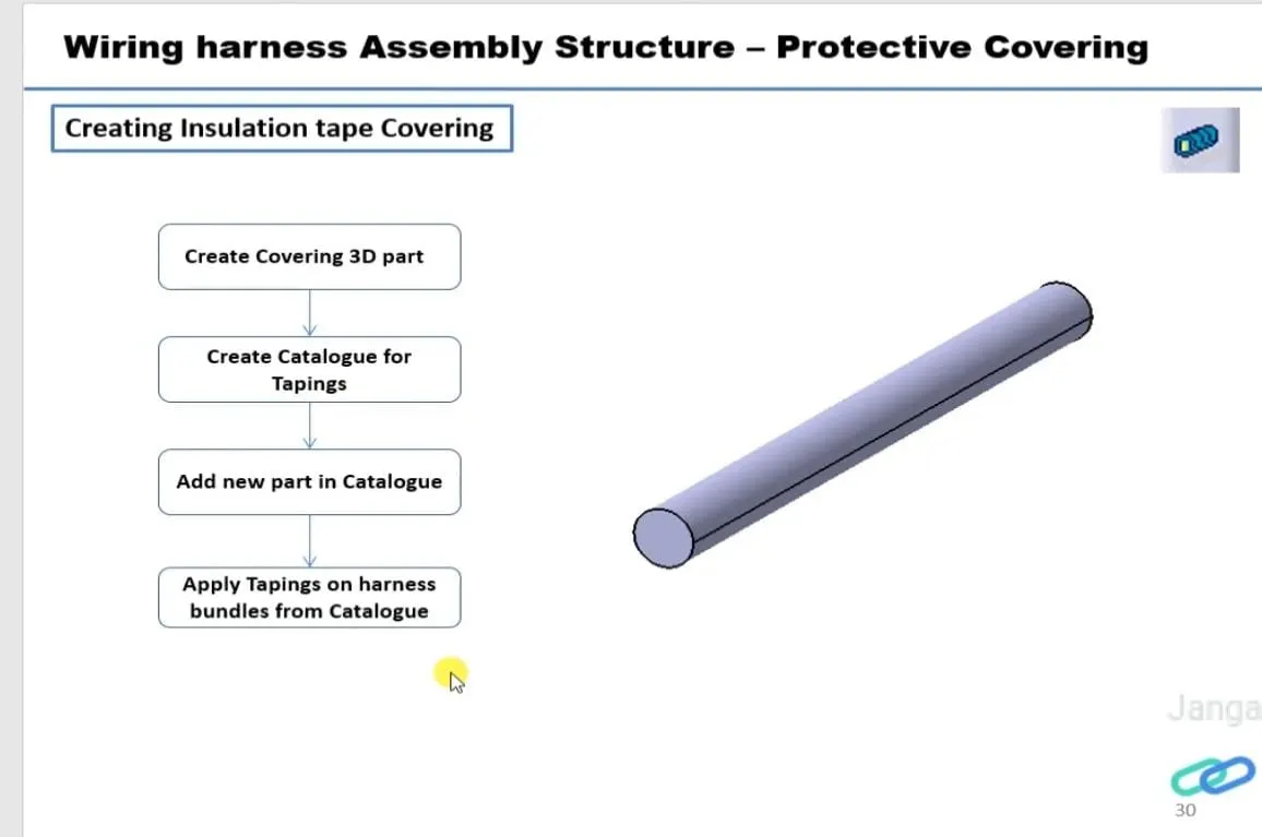
This part can be created in the electrical work bench itself.
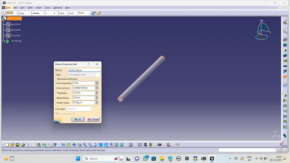
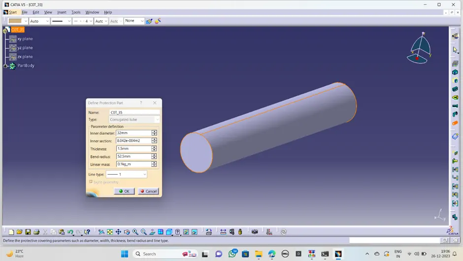
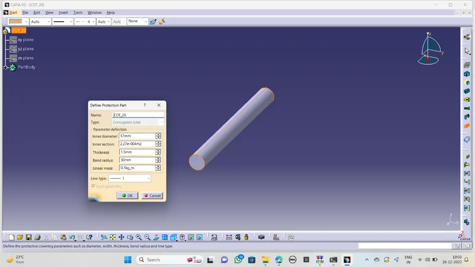
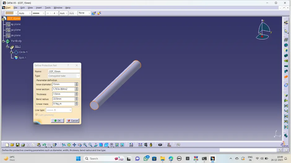
· ·Define the available file as protective part then a dialogue box opens
· ·Select name as COT_tube15mm and size
· ·Enter the inner diameter, thickness and bend radius of the cot tube as given in question box
· · Click on ok
· ·now the tube was created as per our requirement
· repeat the same procedure for the different size of cot tubes. Like 20mm,10mm,35m and 5mm.
cot_tube 10mm
cot_tube 35mm
cot_tube 20mm
cot_tube 15mm
Catalogue:
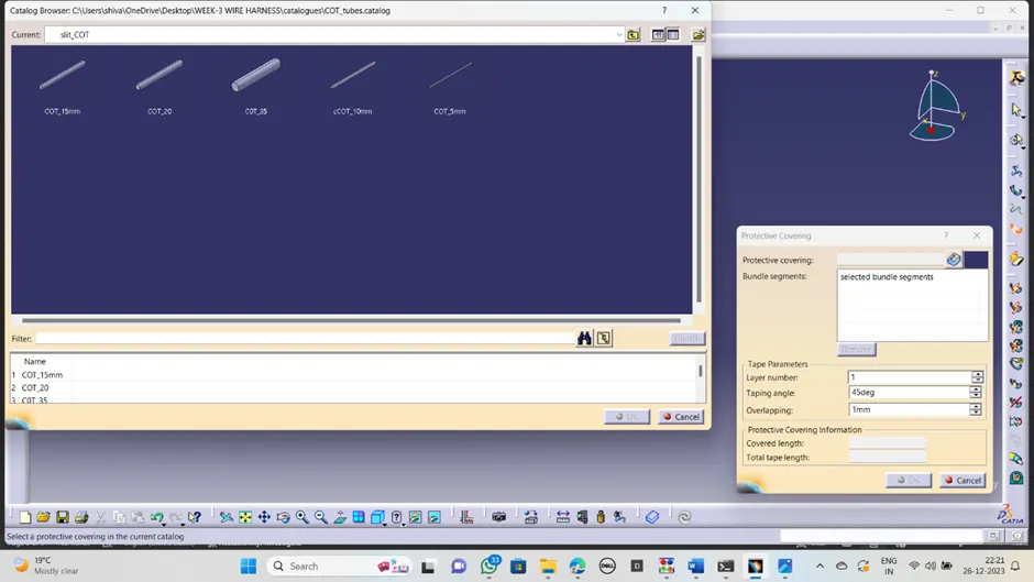
· save the all created COT_tubes
· created the new catalog named with COT_tubes , add it to part family and save it.
· Now in the same work bench available store device ,click it add part family and type.
· Save it ,now all the cot tubes saved into the catalogue.
CONCLUSION:
the given all components are defined as a elctrical components ,created cot tubes as per design and created cotologues for all types of components.