Wiring harness routing & packaging Rules Week 3 Challenge
Wiring harness routing & packaging Rules Week 3 Challenge
Q1. Download following clip cad data & define it as Electrical support using Electrical Part design Workbench. Define all the necessary properties
P-Clamps:
P-clamps are one-piece clips made from metal or plastic that mechanically fasten electrical cables, hydraulic hoses or pipes along their route.
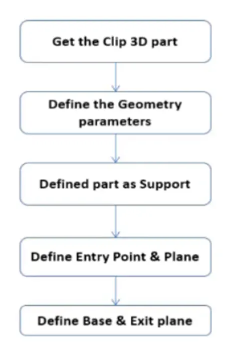
Clip Definition Flow chart:
<!--[endif]-->
Input Clamp: Hellarmann Tyton – 21160129
Process:
<!-- [if !supportLists]-->● <!--[endif]-->Given stp or igs file is converted into part model.
<!-- [if !supportLists]-->● <!--[endif]-->Geometry parameters:
-Create two points one as entry and another as exit point.
-Create planes at two points and another at base.
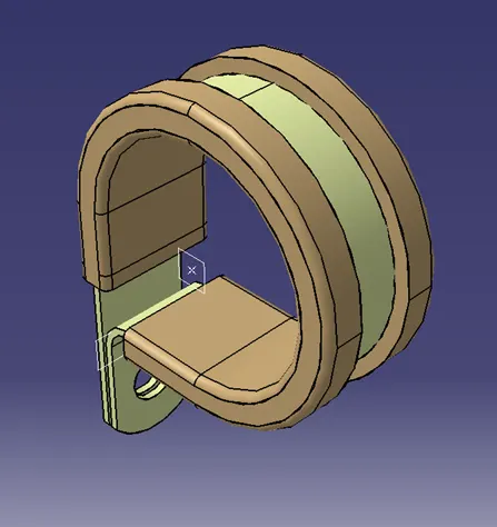 <!--[endif]-->
<!-- [if !supportLists]-->● <!--[endif]-->Switch to Electric part design
<!-- [if !supportLists]-->● <!--[endif]-->Click on support definition - select part - select entry point - select entry plane, exit and base plane.
<!-- [if !supportLists]-->● <!--[endif]-->Again, click on support definition - select part - select exit point - select exit plane and base plane as secondary plane is automatically taken.
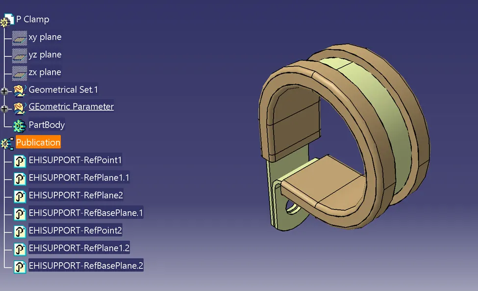 <!--[endif]-->
Q2. Download following Back shell cad data & define it as Electrical back shell using Electrical Part design Workbench. Define all the necessary properties.
Backshell:
A backshell is an accessory that mounts to the rear threads of a connector to enhance its operational characteristics. The primary function of a backshell is to provide strain relief, which minimizes stress from the cable, on the junction where the wires terminate to the contacts.
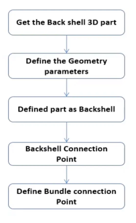
Backshell Definition Flow chart:
 <!--[endif]-->
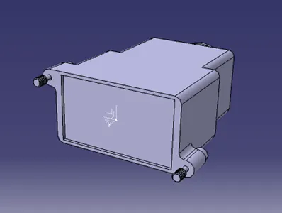
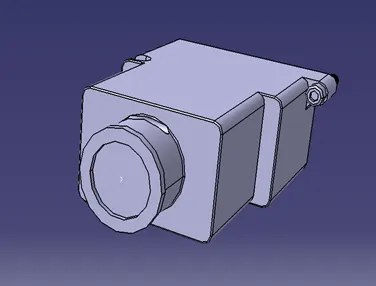
Input Clamp: Tyco 1738312-1
Process:
<!-- [if !supportLists]-->● <!--[endif]-->Given stp or igs file is converted into part model.
<!-- [if !supportLists]-->● <!--[endif]-->Geometry parameters:
-Create a Back shell entry point.
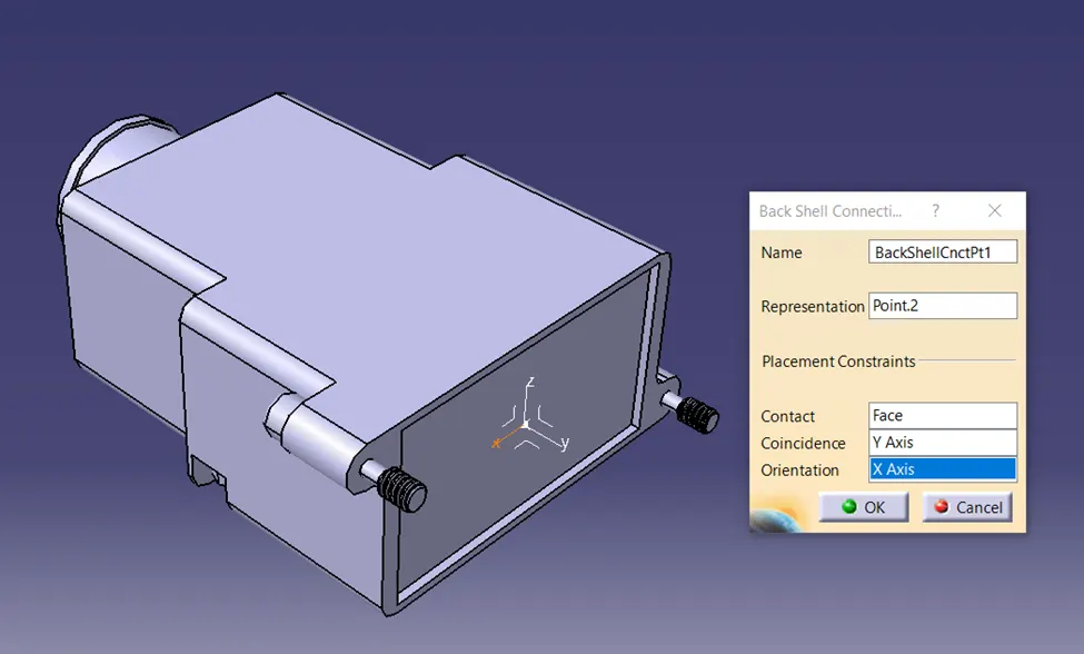
-Create an axis system for back shell connection with connector.
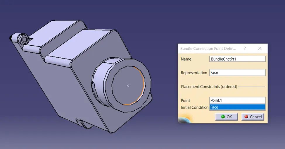
-Create a bundle connection point.
<!--[endif]-->
<!-- [if !supportLists]-->● <!--[endif]-->Switch to Electrical part design.
<!-- [if !supportLists]-->● <!--[endif]-->Define part electrically as a back shell.
<!-- [if !supportLists]-->● <!--[endif]-->Then define the Back shell connection point.<!--[endif]-->
<!-- [if !supportLists]-->● <!--[endif]-->Define bundle connection point.
 <!--[endif]-->
Q3. Create Following Corrugated tubes & Add them in Catalogue under “Slit COT” family.
|
Name |
ID (mm) |
OD (mm) |
Thickness (mm) |
|
15mm COT |
12 |
15 |
1.5 |
|
20mm COT |
17 |
20 |
1.5 |
|
35mm COT |
32 |
35 |
1.5 |
|
10mm COT |
7 |
10 |
1.5 |
|
5mm COT |
3 |
5 |
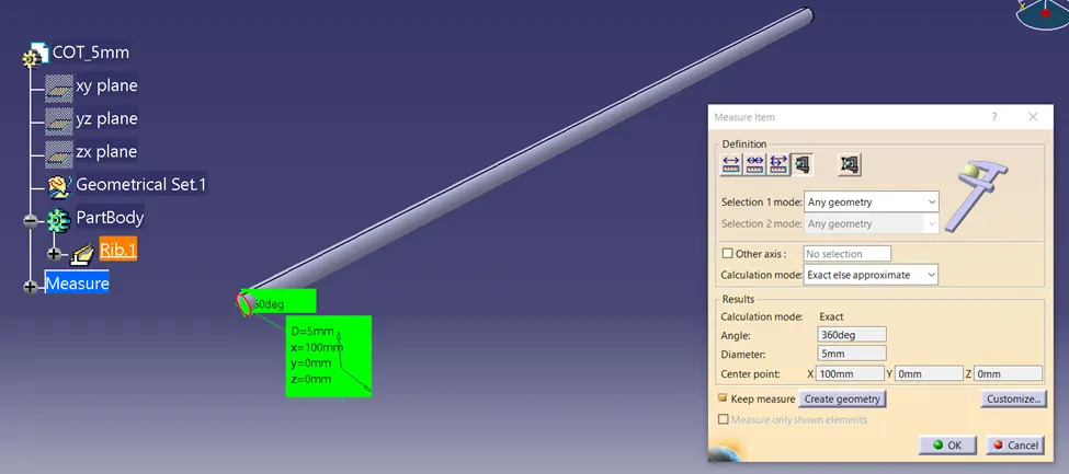
1 |
Protective covering:
The wire harness should be covered with a protective sheath or sleeve to protect it from damage. Providing an extra layer of insulation will protect your wires and cables.
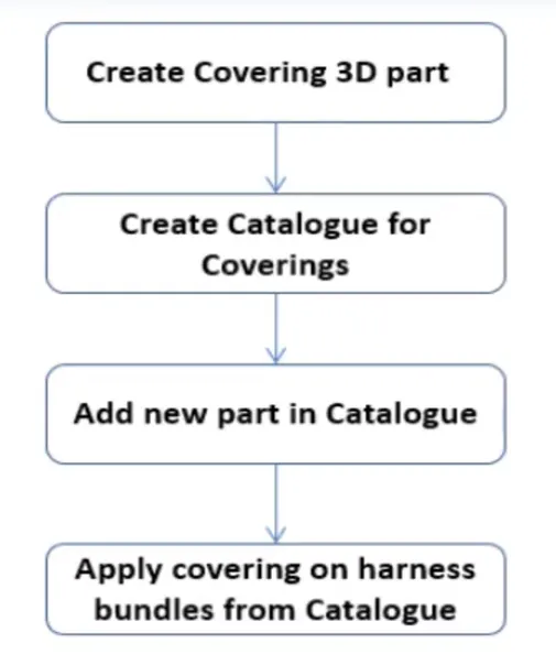
Protection Covering Creation Flow chart:
<!--[endif]-->
Process:
Creating Covering 3D Part:
<!-- [if !supportLists]-->● <!--[endif]-->Open New file
<!-- [if !supportLists]-->● <!--[endif]-->Switch to Electrical part design
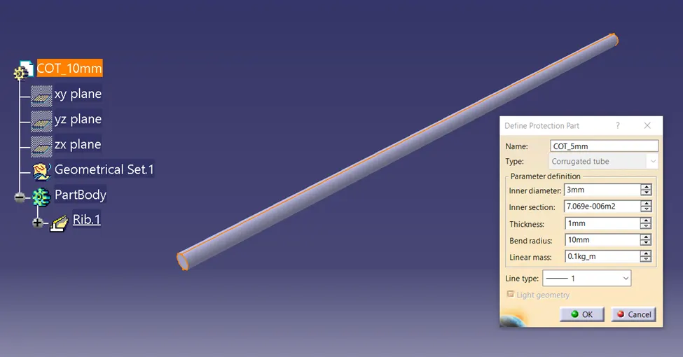
<!-- [if !supportLists]-->● <!--[endif]-->Select Define protection Part
<!-- [if !supportLists]-->● <!--[endif]-->Click on part (on file name in specification tree)
<!-- [if !supportLists]-->● <!--[endif]-->Provide given parameters and bend radius as given in the table.
Catalogue Creation:
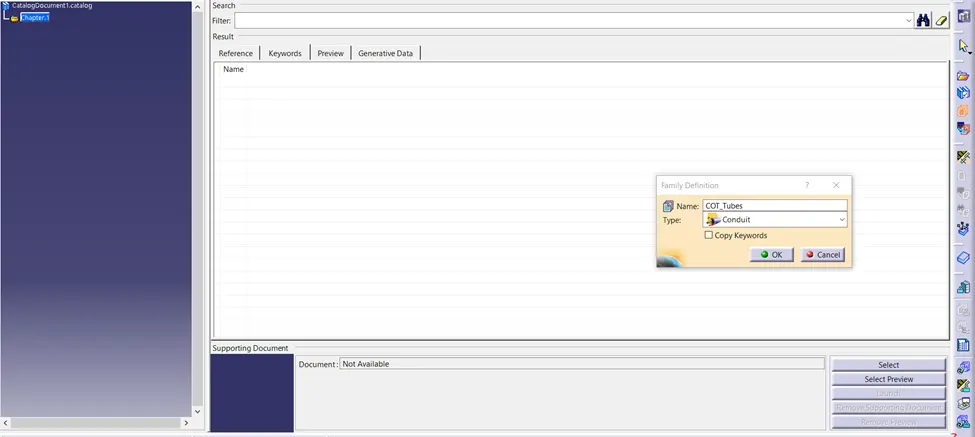
<!-- [if !supportLists]-->● <!--[endif]-->New part - catalogue document - add family - give name - type - select Conduit - save.
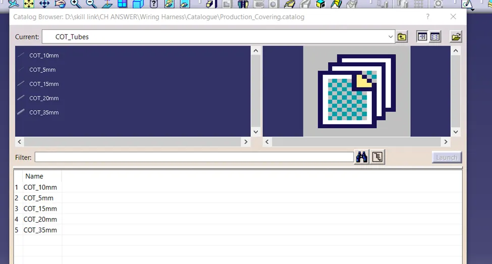
<!-- [if !supportLists]-->● <!--[endif]-->Open part to add catalogue - store device command - select catalogue - family - Slit_cot_tube - ok
COT_Tube 5mm
<!--[endif]-->
 <!--[endif]-->
COT_Tube 10mm
<!--[endif]-->
<!--[endif]-->
COT_Tube 15mm
<!--[endif]-->
<!--[endif]-->
COT_Tube 20mm
<!--[endif]-->
<!--[endif]-->
COT_Tube 35mm
<!--[endif]-->
<!--[endif]-->