Wiring harness routing & packaging Rules Week 3 Challenge
Wiring harness routing & packaging Rules Week 3 Challenge
Aim
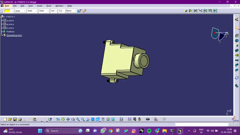
- Download following cad data & define it as Electrical support using Electrical Part design Workbench. Define all the necessary properties.
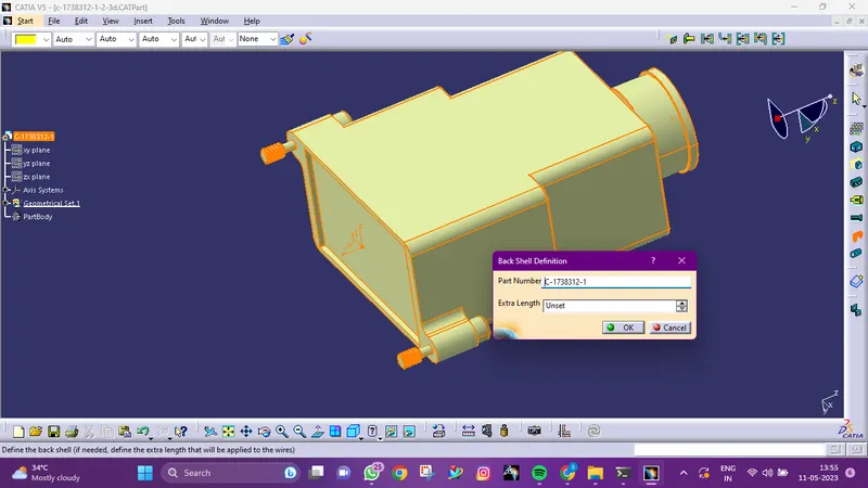
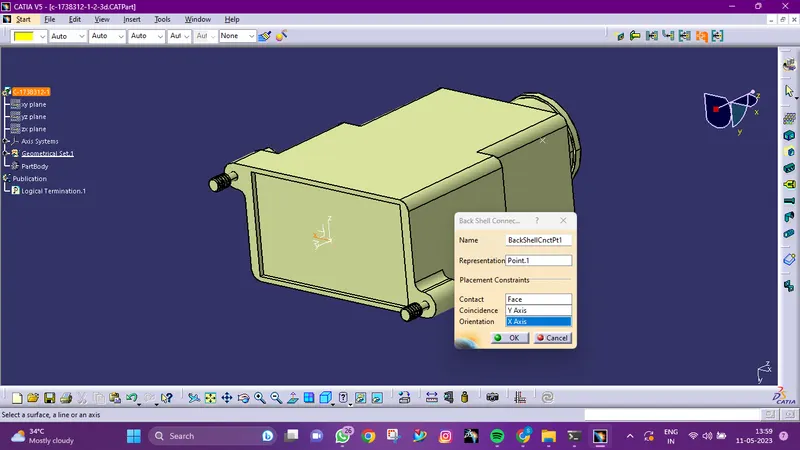
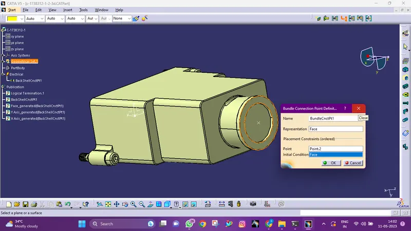
- Download following Back shell cad data & define it as Electrical back shell using Electrical Part design Workbench. Define all the necessary properties.
Tyco 1738312-1 https://www.te.com/usa-en/product-1738312-1.html
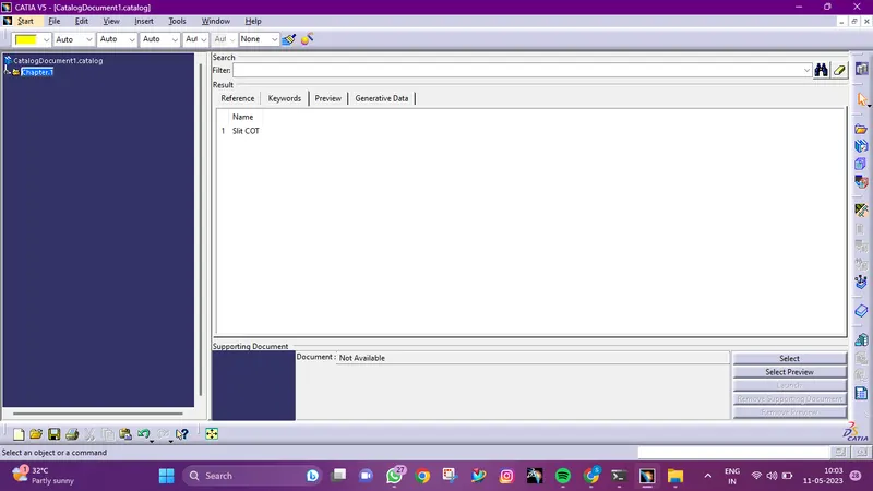
- Create Following Corrugated tubes & Add them in Catalogue under “Slit COT” family.
|
Name |
ID (mm) |
OD (mm) |
Thickness (mm) |
|
15mm COT |
12 |
15 |
1.5 |
|
20mm COT |
17 |
20 |
1.5 |
|
35mm COT |
32 |
35 |
1.5 |
|
10mm COT |
7 |
10 |
1.5 |
|
5mm COT |
3 |
5 |
1 |
INRODUCTION
Wiring Harness Assembly Structure- Clip Defenition:
In a wiring harness assembly, clips are components used to secure and route the wires or cable bundles. Clips provide support, organization, and strain relief to the wiring harness. They are typically made of plastic or metal and are designed to securely hold the wires in place.
The definition of clips in the wiring harness assembly structure involves specifying their locations and attaching them to the appropriate mounting points. Clips are strategically placed along the harness route, often attached to brackets, panels, or other structural components. They ensure that the wires are held securely in position and prevent excessive movement or strain that could lead to damage or interference.
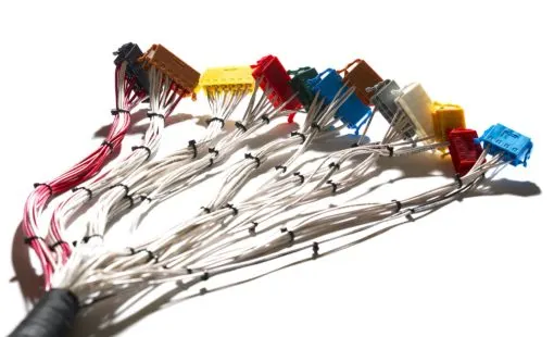
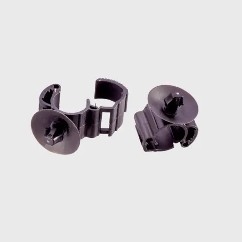
By defining clips within the wiring harness assembly structure, engineers and technicians can accurately plan and document the placement of clips during the manufacturing and installation processes. This helps ensure the proper organization and routing of wires, improving the overall functionality and reliability of the wiring harness assembly.
Wiring Harness Assembly Structure- Connector Defenition:
In a wiring harness assembly, a connector is an essential component used to establish electrical connections between wires or cable bundles and various devices or components. Connectors provide a means of joining, disconnecting, and reconnecting electrical circuits.
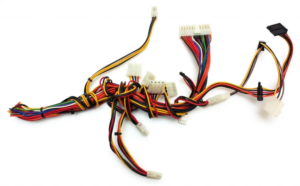
The definition of a connector in the wiring harness assembly structure involves specifying its type, characteristics, and location within the harness. Connectors come in various shapes, sizes, and configurations, depending on the specific application and requirements. They can be male or female, plug or socket, and may include pins, sockets, or terminals for electrical contact.
Connectors are typically placed at specific points along the wiring harness where connections need to be made or where the harness interfaces with external devices or components. They provide a secure and reliable connection, allowing for easy installation, maintenance, and repair of the wiring system.
Backshells:
In a wiring harness assembly, a backshell, also known as a connector backshell or connector accessory, is a protective component that is used to cover and secure the connection between a connector and the cable or wire bundle.
The primary purpose of a backshell is to provide strain relief, environmental protection, and shielding for the connection. It helps prevent excessive stress or tension on the wires near the connector, reducing the risk of damage or disconnection. Backshells also offer protection against moisture, dust, and other environmental elements that could potentially impact the electrical connection.
Corrugated Tubes:
Corrugated tubes, also known as corrugated conduits or wire loom, are protective tubes used in wiring harness assemblies. They are flexible and feature a corrugated or ribbed design, which allows them to expand and contract to accommodate varying wire sizes and bends.
The primary purpose of corrugated tubes is to protect wires and cable bundles from mechanical damage, abrasion, moisture, and other environmental factors. The tubes provide a durable outer layer that shields the wires from impact, friction, and exposure to harsh conditions.
PROCEDURE
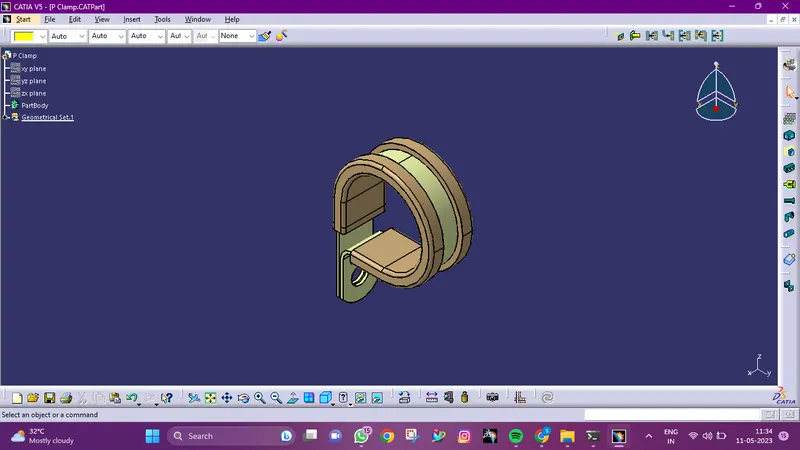
- Download following cad data & define it as Electrical support using Electrical Part design Workbench. Define all the necessary properties.
Process:
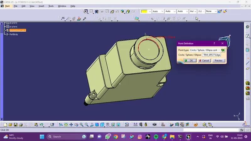
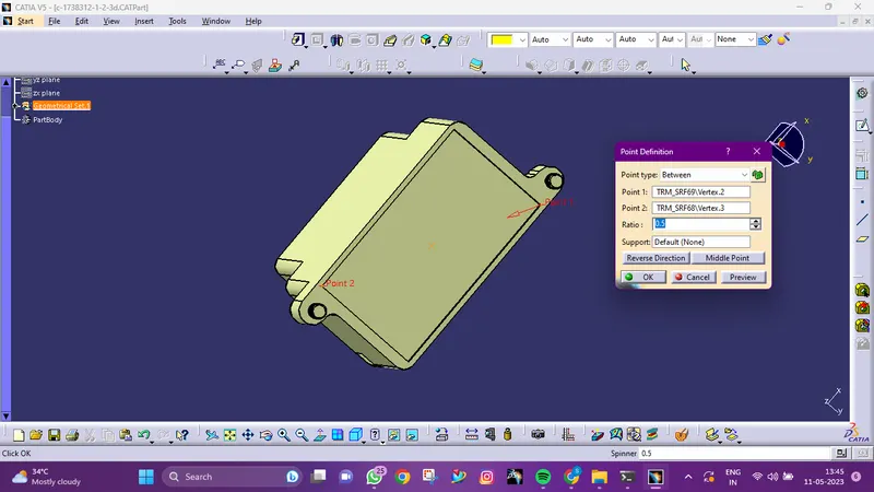
- Add two points. both as points of admission and exit.
- Create two planes, plus one at the base.
- Change the part design to electric
- Click on support definition, then part selection, entry point selection, entry plane selection, and base plane selection.
- Again Click on support definition, then select part, select exit point, select exit plane, with the base plane being automatically taken as the secondary plane.
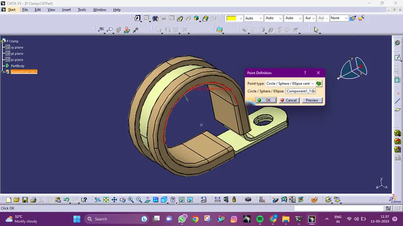
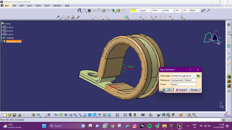
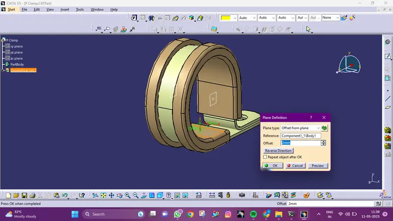
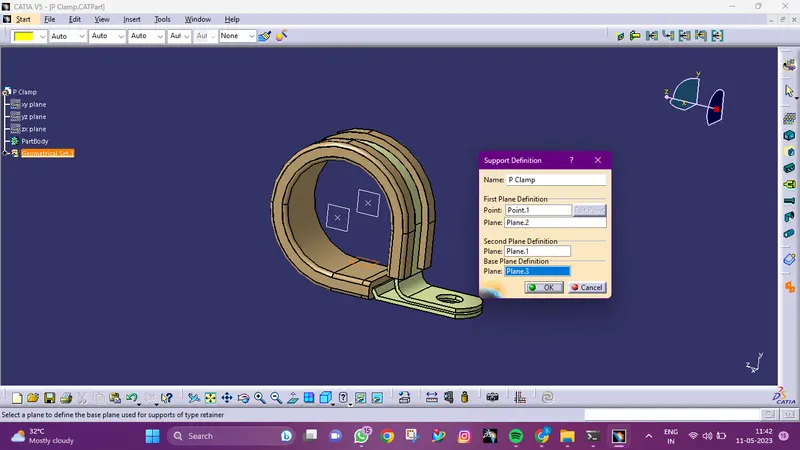
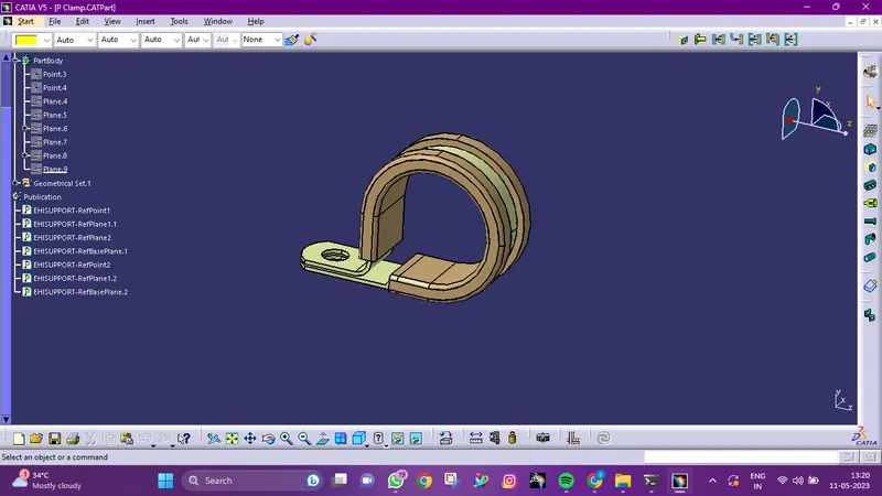
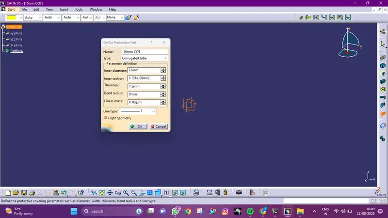
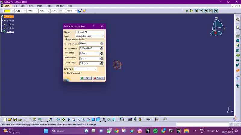
- Create Following Corrugated tubes & Add them in Catalogue under “Slit COT” family
Process:
- Change to electrical part design
- The Define protection Part option
- On the file name in the specification tree, click the part.
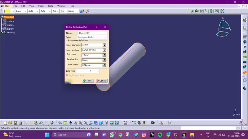
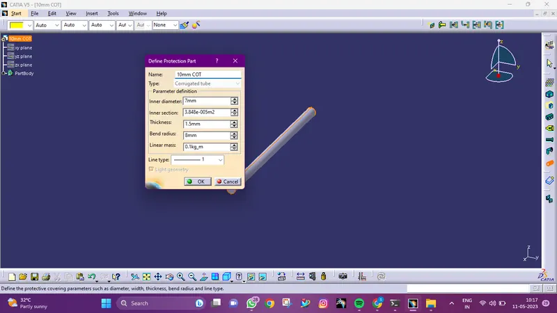
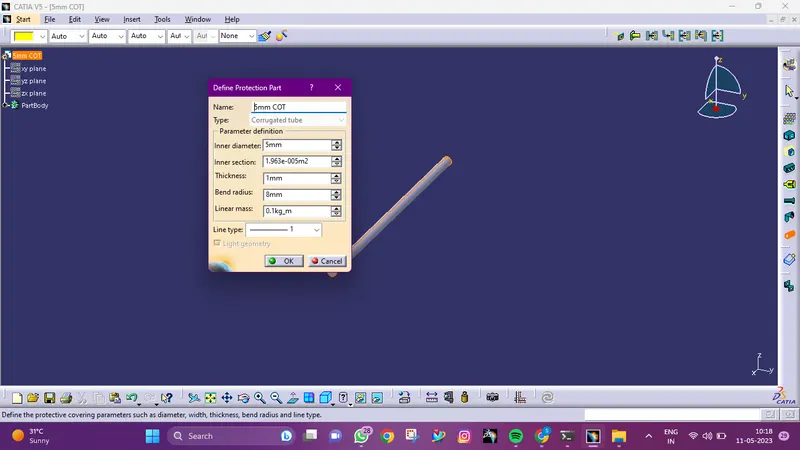
- provide the given parameters
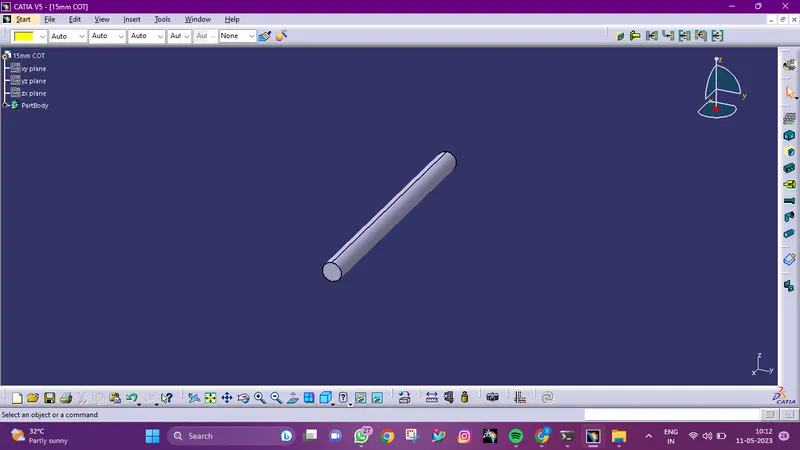
15mm COT:
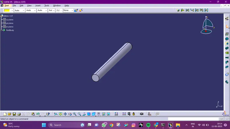
20mm COT:
35mm COT:
10mm COT:
5mm COT:
CATALOUGE CREATION:
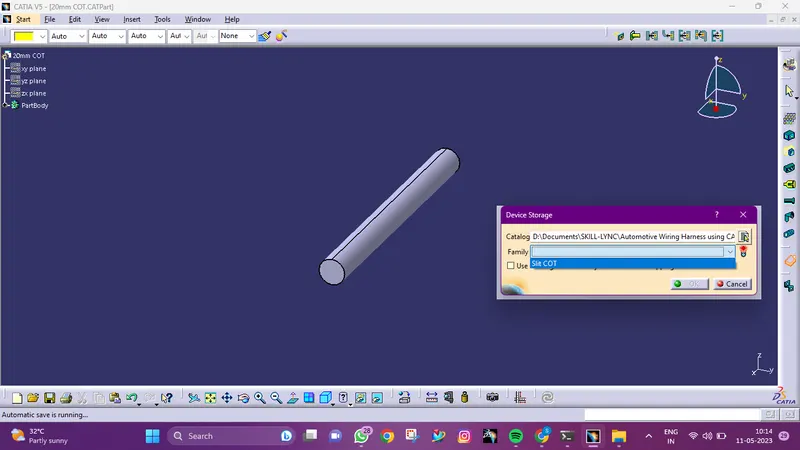
- Download following Back shell cad data & define it as Electrical back shell using Electrical Part design Workbench. Define all the necessary properties.
Tyco 1738312-1 https://www.te.com/usa-en/product-1738312-1.html
Process:
- Entrance point for the back shell, construct.
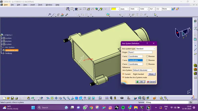
- For the back shell entrance, establish an axis system.
- Make a connecting point for a bundle.
- Change to designing electrical parts.
- Back shell is a portion electrically defined.
- The Back shell connection point is then defined.
- Bundle connection point definition.