Week 8 - Challenge 2 - Switch Bezel Design
SWITCH BEZEL DESIGN :-
Aim-
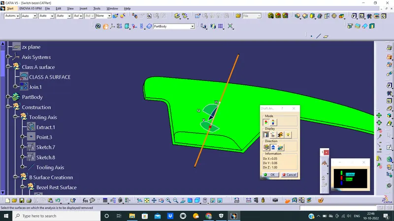
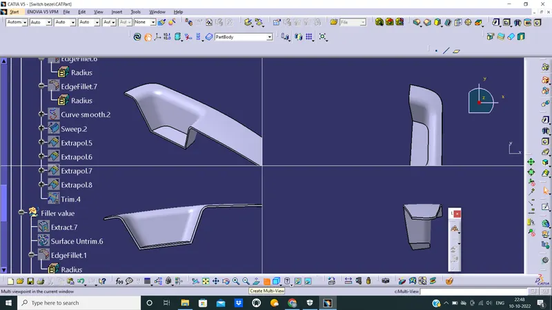
Create the Switch Bezel Plastic component through the given Class-A surface. Start with, the tooling axis for the given Class-A Surface should be created meeting the requirements of the draft angle and at the end perform the Draft analysis on the model. Thickness of the component is 2.5 mm.
Given Class A Surface-
Tooling Axis-
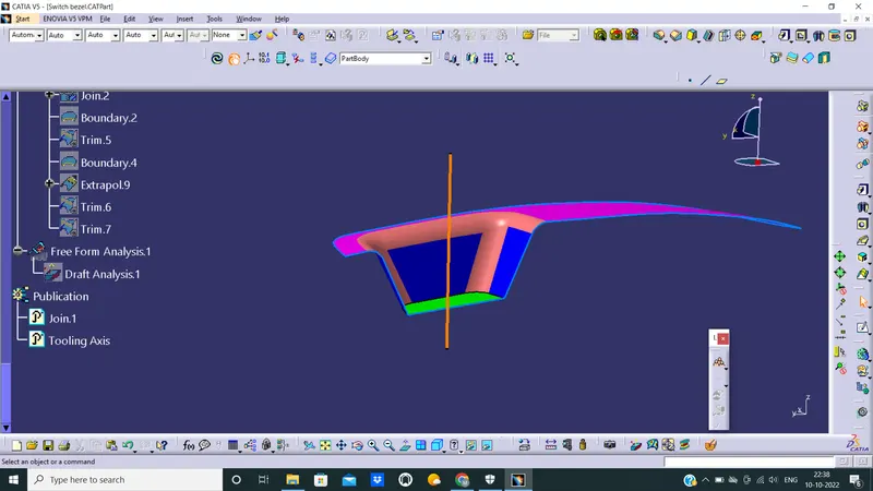
Create a intersection along Y direction. then create two line along side wall. After that create a bisecting line using that two line.
Create another intersection along X direction. then create a line along that one wall. After that create a line of 4 deg. with that line.
Then using previus bisecting line of Y axis and angled line of X axis, create another bisecting line and tht will be the tooling axis.
Class B Surface-
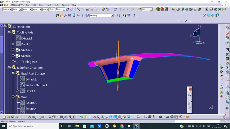
Class B usually the surface where all engineering aspects and support creations are done. The B surface Creation is performed using surface operations in CATIA which is an offset from Class A with dimension proportional to the thickness of the part. In Switch bezel the B surface is offset 2.5mm from the input which is the thickness of the part. The B surface is an extrapolated surface compared to A surface and forms the bottom skin of the part.
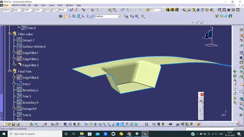
Class C Surface-
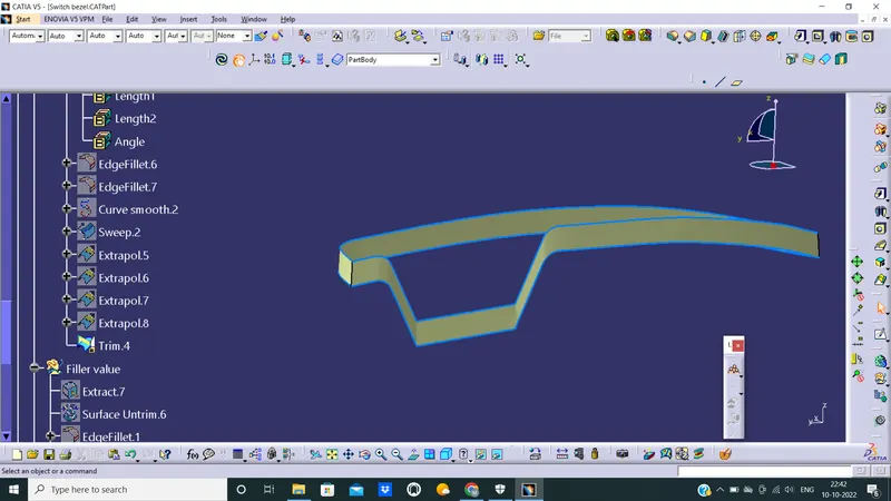
Closed Body Creation-
All 3 surface are trimed properly and joined togather. Check if there is any open edge, then close that. After that using 'Closed Surface' command make tht solid. And ensure closed body formed in a part body.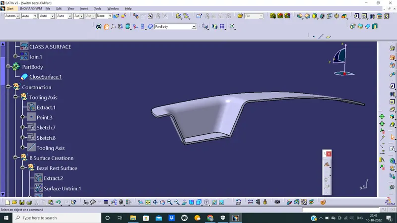
Draft Analysis:
This is very importatnt part
The Color Codes are classified and Draft Angle are applied. Then the Running point analysis is used to around the part to analyze the permissible draft angles and the analysis is saved.