Wiring harness routing & packaging Rules Week 3 Challenge
Wiring harness routing & packaging Rules week 3 Challenge
Aim:-
Q1. Download the following cad data & define it as Electrical support using the Electrical Part
Design workbench. Define all the necessary properties.
P clamp
Note: if you face any issue with point definition, or point selection, Right-click on the point
definition window and use the reset option.
Solution:-
Clip/Clamp Definition -
. Get the clip 3D part
. Define the Geometry Parameters
. Define part as support
. Define the entery point & plane
. Define the exit part & plane
Mechanical Part Design Workbench
. Define the Geometry Parameters
Points and Planes -
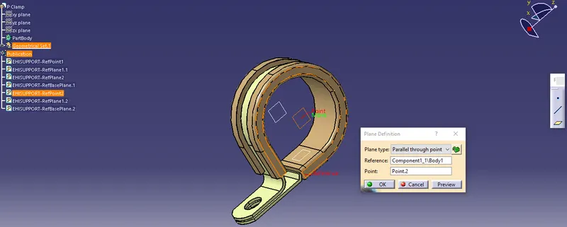
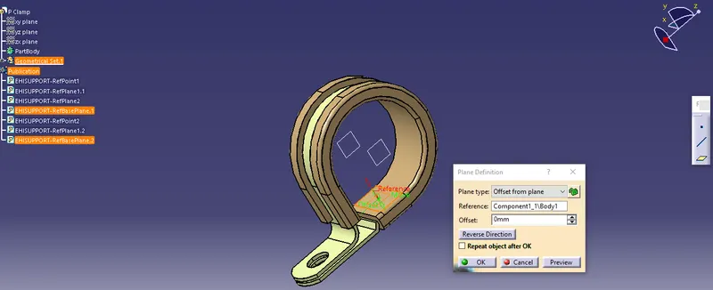
Defining the points for both sides through point definition.
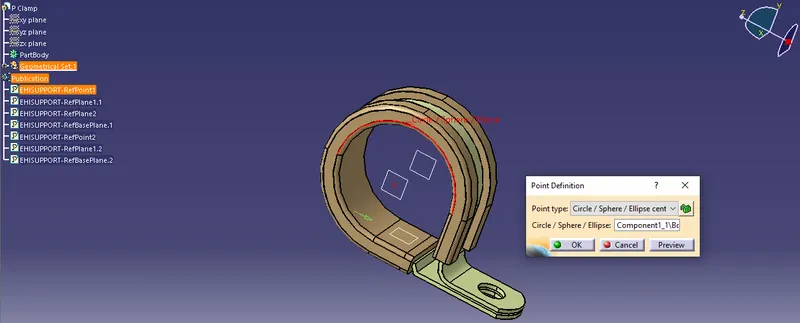
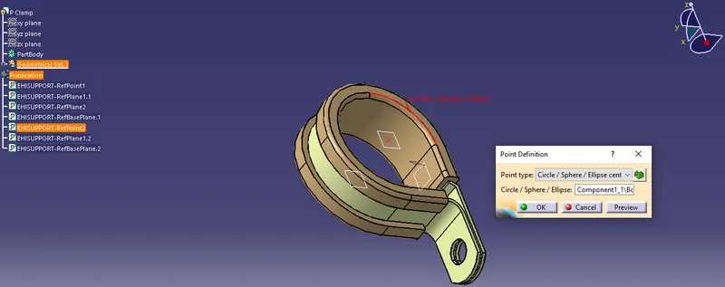
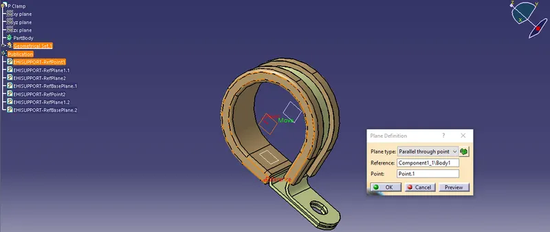
Creating entry, exit, and base planes through plane definition.
Electrical Part Design Workbench
. Define part as support
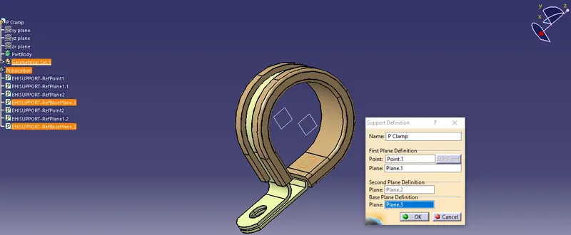
The support definition for the p clamp is defined twice to make bilateral connectivity. The point
selected for the side will be the entry side of the bundle, which is done for both sides. The entry
point & plane, Base & exit plane is defined in the support definition.
Aim:-
Q2. Download the following Back shell cad data & define it as an Electrical back shell using the Electrical
Part Design Workbench. Define all the necessary properties.
Tyco 1738312-1 https://www.te.com/usa-en/product-1738312-1.html
Solution:-
Defining the Backshell-
. Get the Backshell 3D part
. Define the Geometry Parameters
. Define part as Backshell
. Define Bundle connection point
Mechanical Part Design Workbench
. Define the Geometry Parameters
Points and Axis system
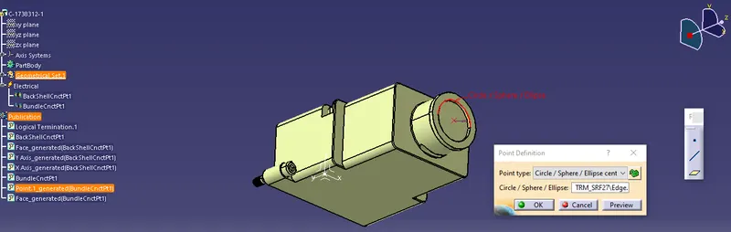
Defining the points through point definition for bundle entry and mating sides.
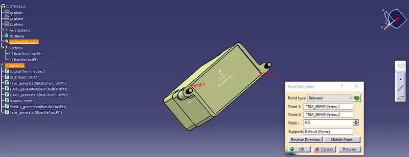
Defining the axis system for the mating side, where the y-axis is in the mating direction, the x-axis
to the side, and the z-axis is directed upward.
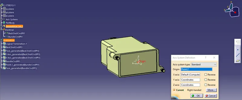
Electrical Part Design Workbench
. Define part as Backshell
Part is defined as backshell using the back shell definition command.
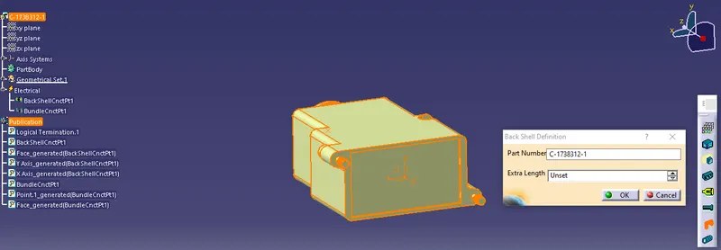
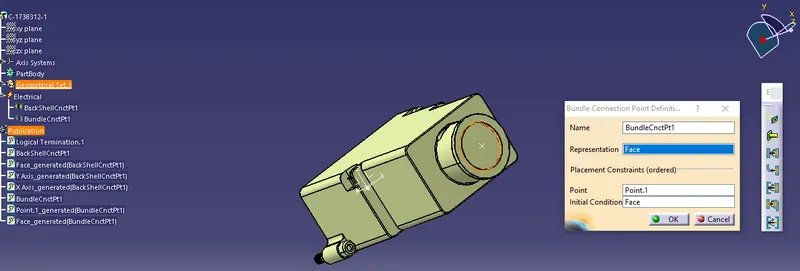
. Backshell connection point
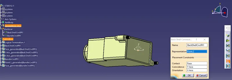
Define Bundle connection point.
Aim:-
Q3. Create Following Corrugated tubes & Add them in Catalogue under “Slit COT” family.
Name ID(mm) OD(mm) Thickness(mm)
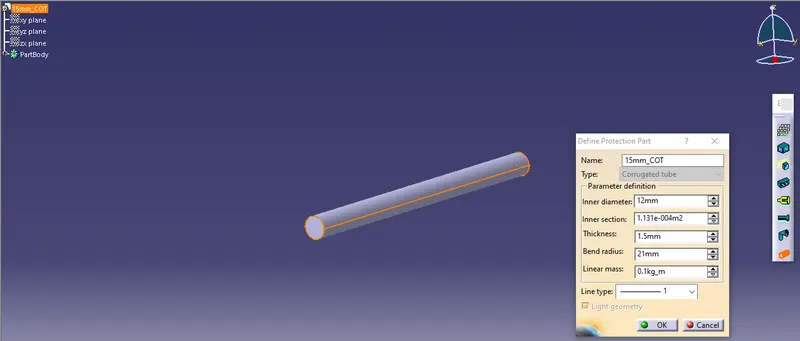
15mm COT 12 15 1.5
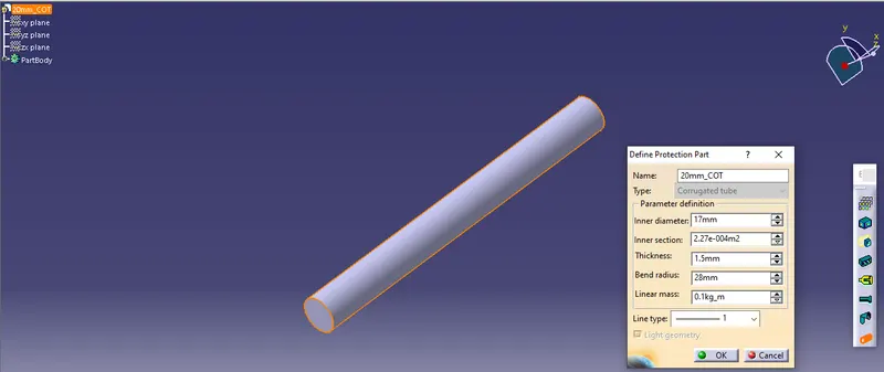
20mm COT 17 20 1.5
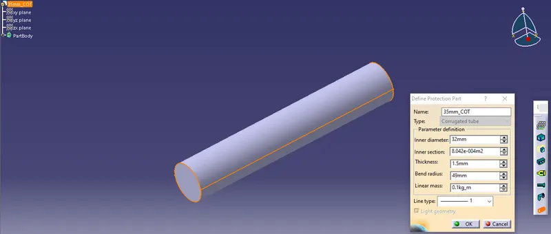
35mm COT 32 35 1.5
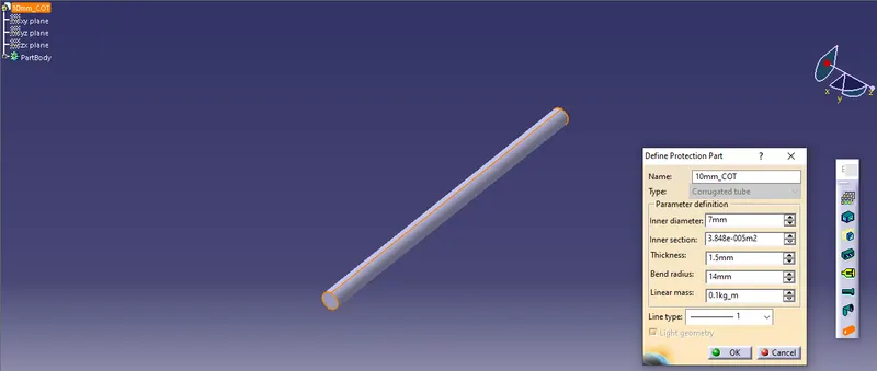
10mm COT 7 10 1.5
5mm COT 3 5 1
Solution:-
Creating Projecting Covering -
. Create a covering 3D part
. Create a catalog for coverings
. Add a new part to the catalog
. Apply covering on harness bundles from the catalog
Electrical Part Design Workbench
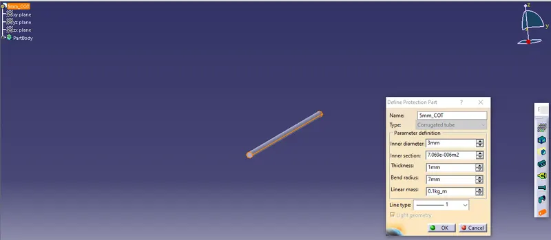
. Define the projection part
Specifying inner diameter, Thickness, and the Bend radius which is 1.4 time the outer diameter.