Wiring harness routing & packaging Rules Week 3 Challenge
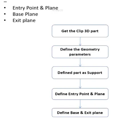
Q1. Download the following cad data & define it as Electrical support using Electrical Part design Workbench. Define all the necessary properties.
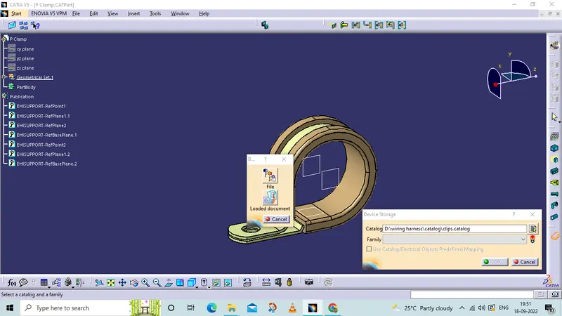
P Clamp
Tree Structure
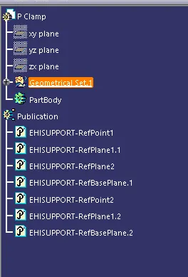
creating points and planes
In part design workbench
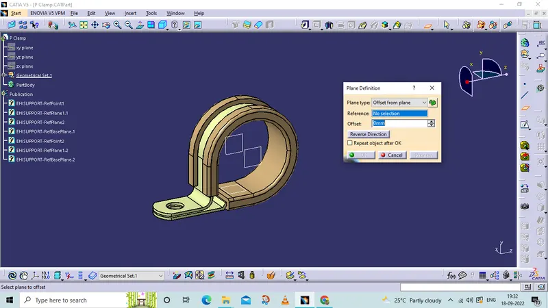
Switched to part design- electrical part design.
Define the support part in the electric part design workbench
Then define the entry and exit points to the
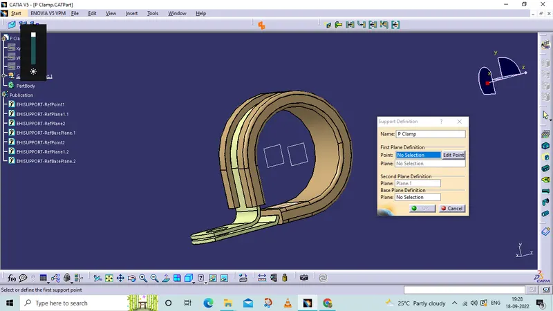
ADDED TO CATALOG OF CLIPS
Q2. Download the following Back shell cad data & define it as an Electrical back shell using an Electrical Part Design Workbench. Define all the necessary properties.
Tyco 1738312-1
Downloaded from TE website back shell
and create points and axis system to the backshell connection point. and if require a bundle connection point also define
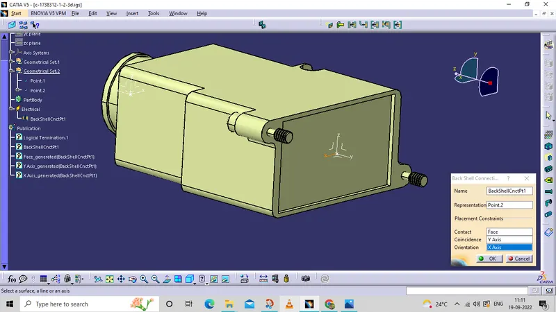
after creating the bundel connection point and axis moved to electrical part design W/B
and define as a backshell 
then define a bsckshell point
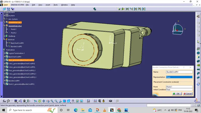
define the bundle connection point
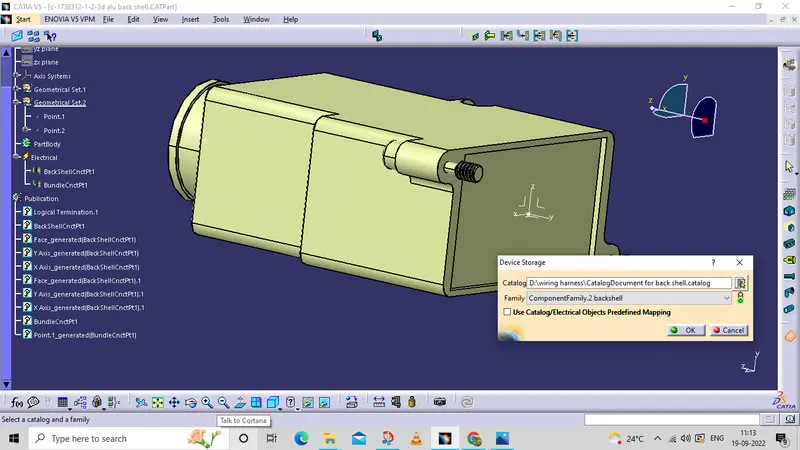
added to backshell catalog
Q3. Create Following Corrugated tubes & Add them in Catalogue under “Slit COT” family.
|
Name |
ID (mm) |
OD (mm) |
Thickness (mm) |
|
15mm COT |
12 |
15 |
1.5 |
|
20mm COT |
17 |
20 |
1.5 |
|
35mm COT |
32 |
35 |
1.5 |
|
10mm cot |
7 | 10 | 1.5 |
|
5mm COT |
3 |
5 |
1 |
1.)
|
15mm COT |
12 |
15 |
1.5 |
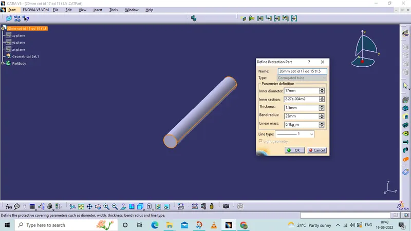
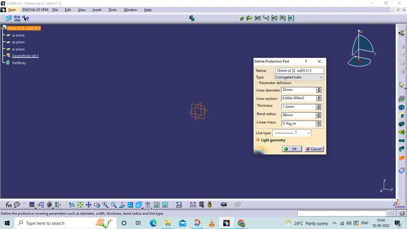
creating the cout tube with perameters:
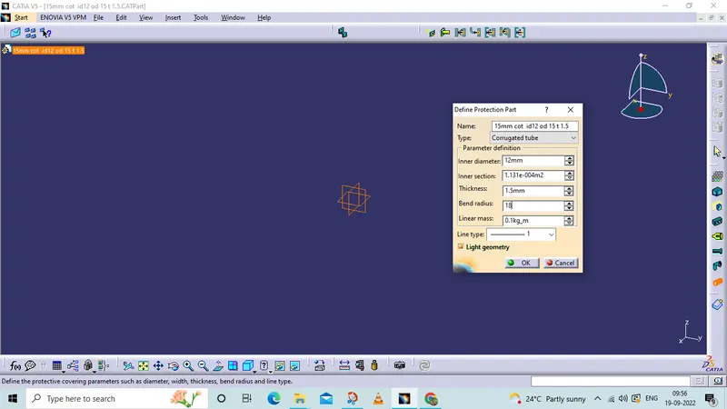
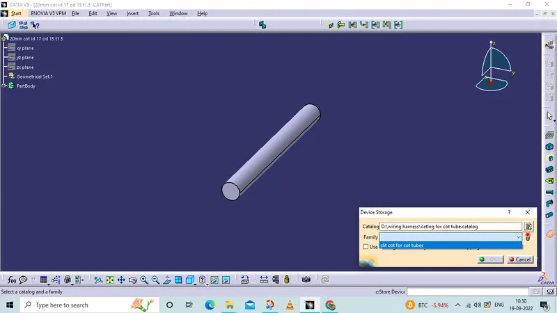
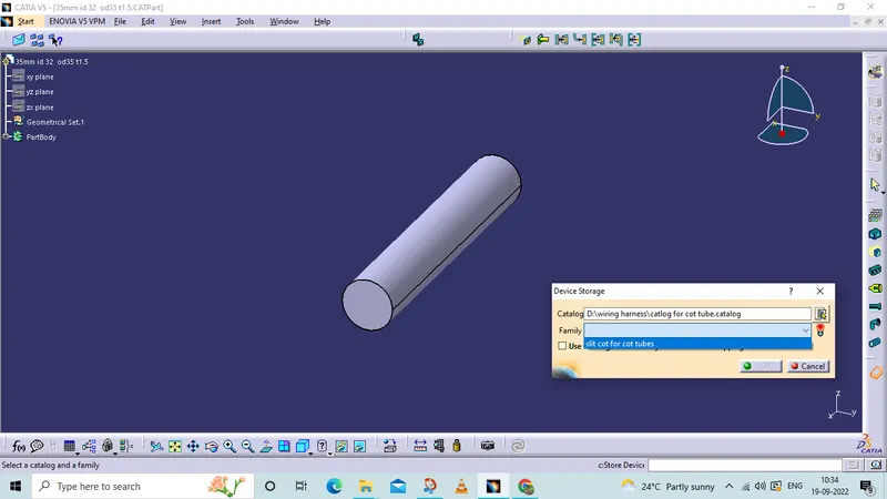
added to cataloug
2.)
|
20mm COT |
17 |
20 |
1.5 |
3.)
|
35mm COT |
32 |
35 |
1.5 |
4.)
|
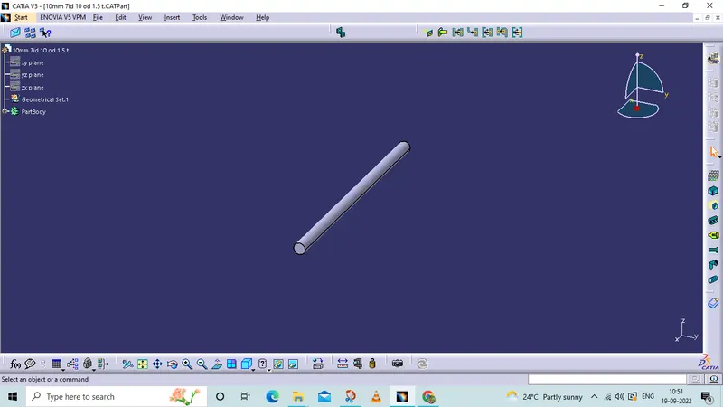
10mm cot |
7 | 10 | 1.5 |
5.)
|
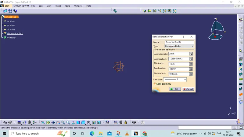
5mm COT |
3 |
5 |
1 |
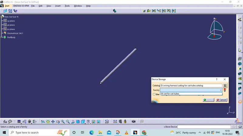
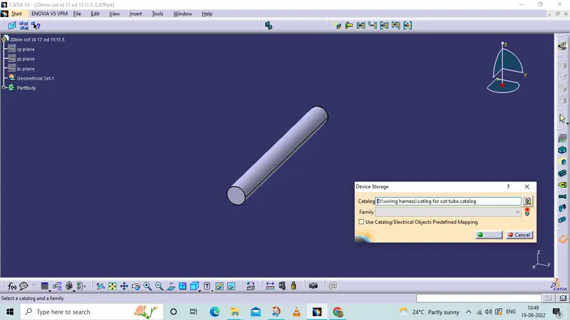
stored cout tubes
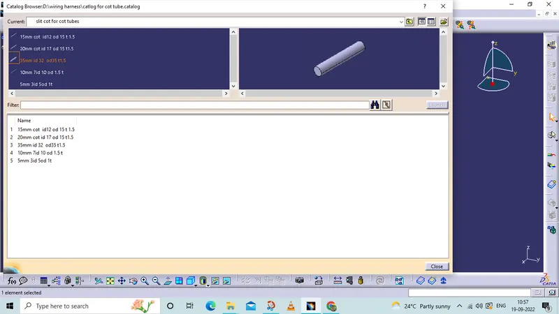
am added a zip file of created parts