Wiring harness routing & packaging Rules Week 3 Challenge
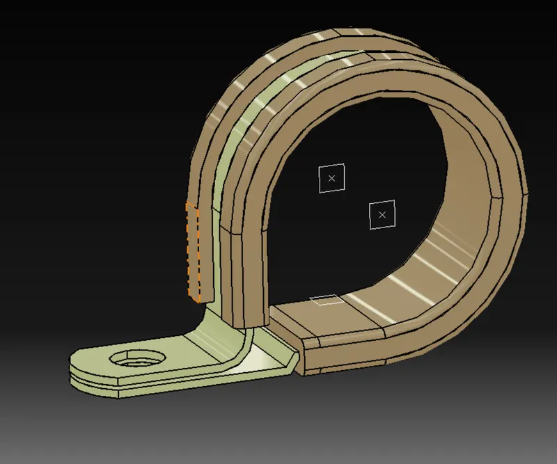
P Clamp
- The P clamp file was downloaded and opened as a Mechanical part design.
- Two points were made which were then defined as entry and exit points.
- Two planes were defined on those points which were perpendicular to the bundle entry and exit.
- A base plane was made about 2mm above the flat surface and within the clip's boundaries.
- Then in the Electrical Part Design it was defined as support part for the entry point and the points and planes were selected as the parameters.
- The same process was repeated for the exit point.
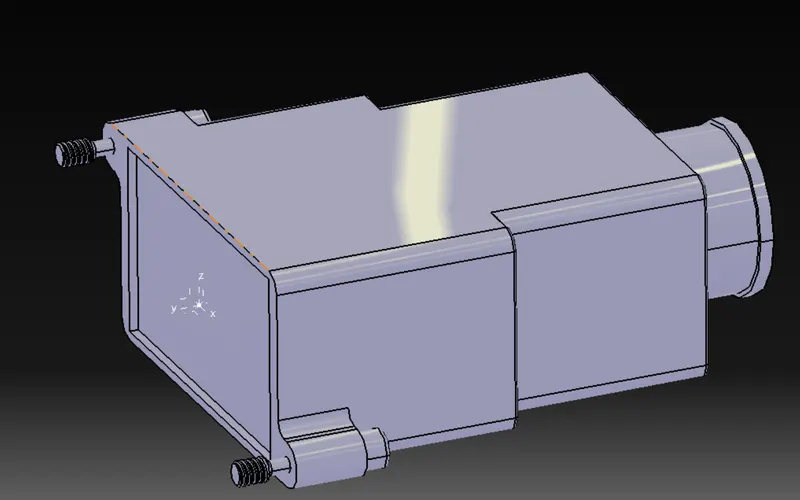
Back Shell
- The P clamp file was downloaded and opened as a Mechanical part design.
- Two points were made which were then defined as backshell connection and bundle connection points
- An axis system was made with the correct orientation was made on the bundle connection point.
- Then in the Electrical Part Design it was defined as Back Shell with appropriate parameters.
Corrugated tubes
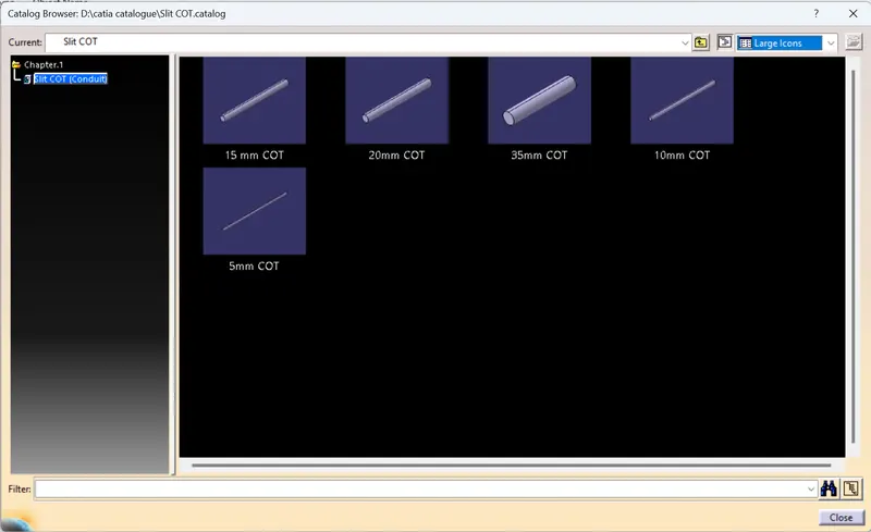
- In the Electrical Part Design --> Define Protection Part.
- The inner dia and thickness were selected.
- And then the parts were added to the catalog named Slit COT which was specially created for Corrugated tubes.