Wiring harness routing & packaging Rules Week 3 Challenge
AIM :
Define given clamp and back shell as an electrical support and electrical back shell and add their necessary properties using Electrical part design workbench in CATIA V5.
OBJECTIVE :
Objective of this project is to first download the given file from the given link and define all of them as an electrical support and back shell and give all the required electrical properties to them using the electrical part design workbench in CATIA V5.
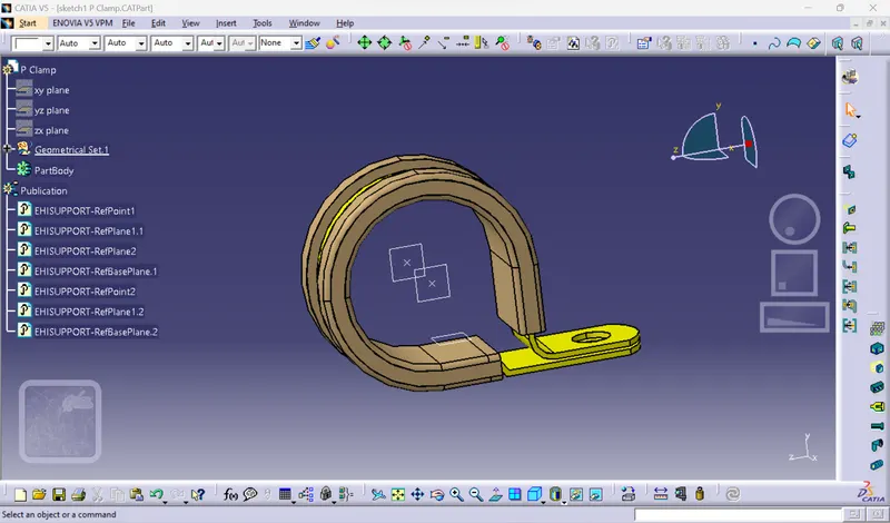
Firstly we have to download the 3D CAD model of P-Clamp from the link which is provided above. Extract the Zipper file and open it in the CATIA V5.
- Open the CATIA V5 and click on file > open > click on the extracted file of P-clamp.
- The 3D CAD model is appered on the screen. click on Start > go to Part Design.
- Click on Point > Select the Circle/Sphere/Ellipse option and click on the Cricle, a point is created in th center of the clamp.
- Click on Plane Define and create a plan at the entry side and the exit side by selecting the option Parllel through point, Referance will be the component of the body and point will be the point1 which was created earlier and repeat the same process to other side point will be point2 by selecting the same options.
- Again click on Plane Define and select the offset from plane option. Select the Face as Referance and type 2 in the offset, click ok.
- Same repeate the process at the other side of the clamp. Give the point at the middle of the clamp with the help of Circle/Sphere/Ellipse option.
- Click on Plane Define and create a plan at the entry side and the exit side by selecting the option Parllel through point, Referance will be the component of the body and point will be the point1 which was created earlier and repeat the same process to other side point will be point2 by selecting the same options.
- Again click on Plane Define and select the offset from plane option. Select the Face as Referance and type 2 in the offset, click ok.
- Go to Start > click on Electrical Part Design
- Click on Support Definition > click on the 3D design(it is converted intpo electrical component), it appears automatically the Name as P Clamp. In First Plane Definition Point will be Point1(We have to click on the initial point) and Plane will be Plane1(we have to click on the plane) > In Second Plane Defination Plane will be Plane2(click on the Second plane wich is opposite to our first plane) > In Base Plane Defination the Plane will be Plane3(click on the base plane wich is created by using offest option).
- Again click on Support Definition > click on the Clamp > In First Plane Definition, it will not take the point. So we have to right click on the option and click on Reset option, now it is available to select the point and the plane. The point will bw Point2 and plane will be Plane2. In Second Plane Defination Plane will be Plane2, it is inbuilt(it can't be changed). In Base Plane Defination the Plane will be Plane3
- All the Electrical Parts are defind.
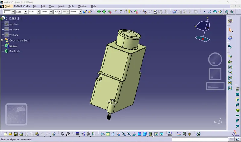
- A2. We have to download the CAD 3D Back Shell from the above link and extract it and open the file in the CATIA V5.
- Open the CATIA V5, go to file > open> click on the extracted file > Go to Start > Click on Part Design.
- Click on Point > Select the Circle/Sphere/Ellipes option > Click on the Cirlce to create a middle point and It is created.
- Again create a point at the another side of the back shell > Click on Point > Select the Between option > Click on two ends to create a point in the Middle > Click on Middle Point option.
- Click on Axis System Definition > Click on Point (The origine will be point2), 'X-axis ' should be facing towards locking mechanism (if it is facing in another direction click on right click > select Rotation option > type 90, it wiil rotate in 90 degrees), 'Y-axis' should be facing towards Normal to the Plane, 'Z-axis' can be facing either upside or downside. Axis is created.
- Go to Start > Electrical Part Design > Click on Back Shell Definition > click on the CAD 3D Design and it is now converted into Electrical Component. Extra length be unset.
- Click on Back Shell Connection Definition > Representaion will be the point(Click on the point2) > Contact will be the Face(Click on the face) > Coincidence will be the 'Y axis' > Orientation will be 'X axis' > Click Ok.
- Click on Bundle Connection Point Definition > Representation will be Face(Click on the face) > Point will be the Point1(Click on the point) > Initial Condition will be again the face(Click on the face) > Click ok.
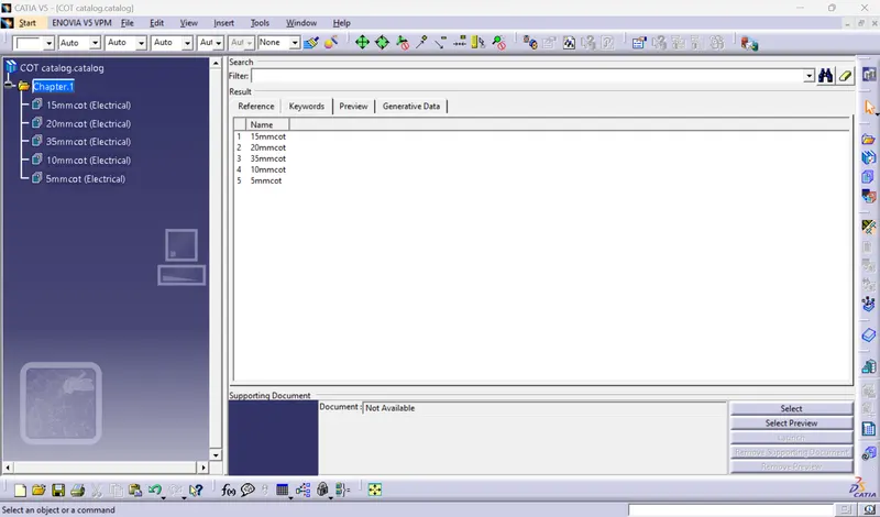
Create Following Corrugated tubes & Add them in Catalogue under “Slit COT” family.
|
Name |
ID (mm) |
OD (mm) |
Thickness (mm) |
|
15mm COT |
12 |
15 |
1.5 |
|
20mm COT |
17 |
20 |
1.5 |
|
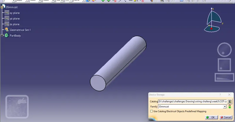
35mm COT |
32 |
35 |
1.5 |
|
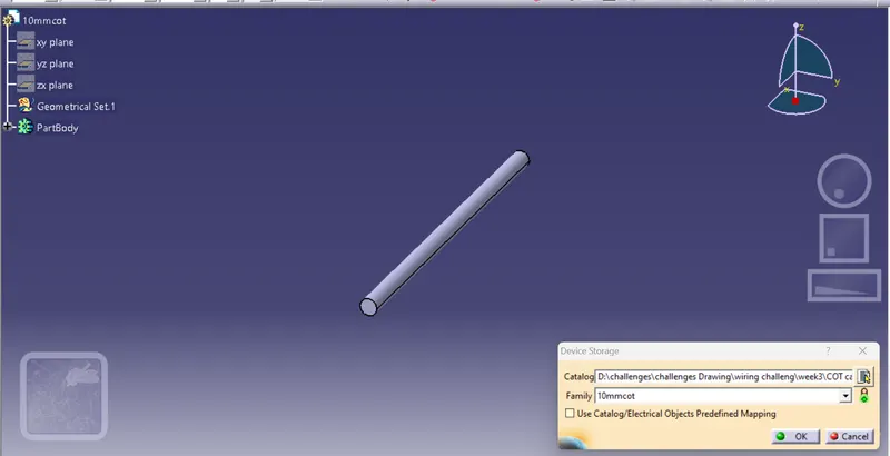
10mm COT |
7 |
10 |
1.5 |
|
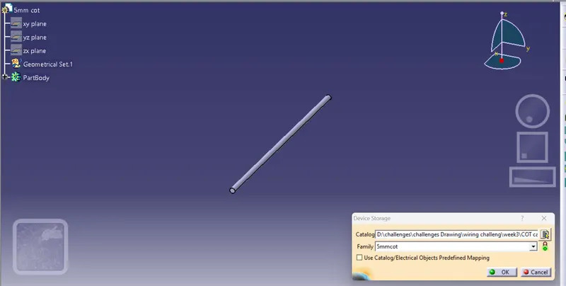
5mm COT |
3 |
5 |
1 |
15 mm COT TUBE: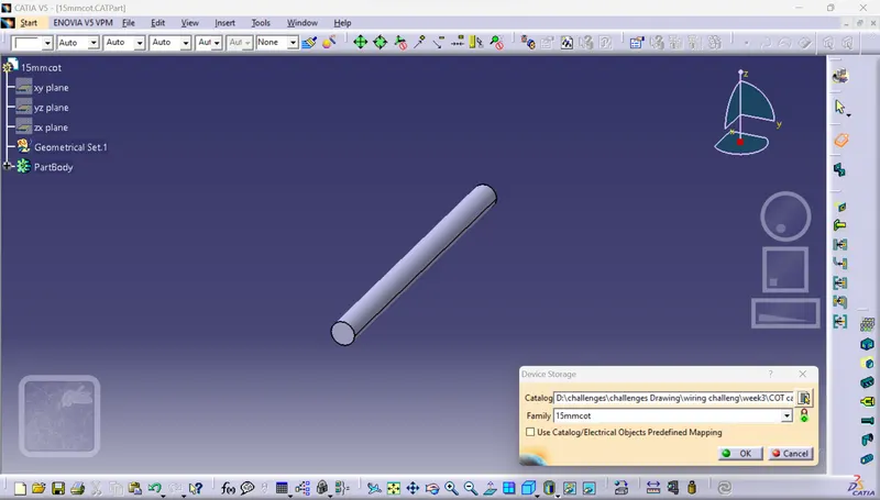
20 mm COT TUBE: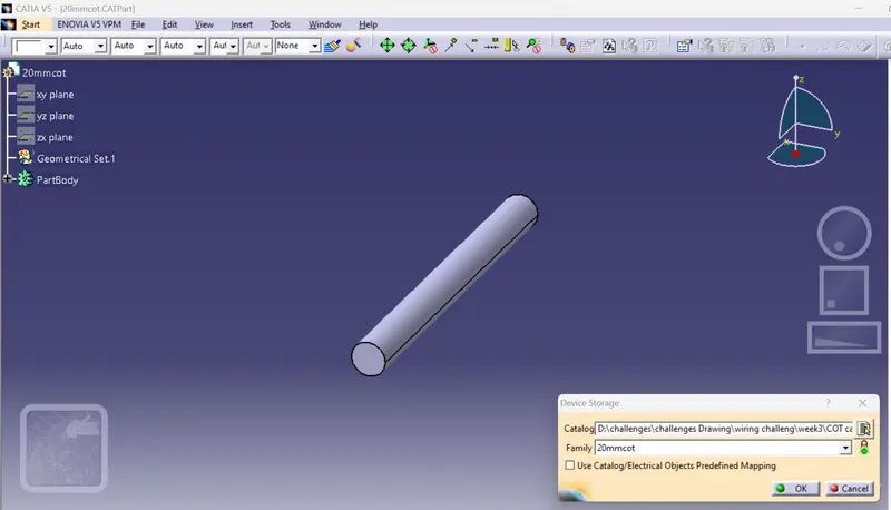
35 mm COT TUBE:
10 mm COT TUBE:
5 mm COT TUBE:
CATALOG
CONCLUSION:
- From the above assignment we learnt how to define the Electrical support for a P-Clamp and also define its Electrical properties.
- We also learnt how to Electrical Backshell for a Backshell component and also define its Electrical properties.
- We also learnt how to make Corrugated Tubes of different diameters and also save them in the respective families in the Corrugated Tubes catalogues.