Challenge

Wiring harness routing & packaging Rules Week 3 Challenge

Wiring harness routing & packaging Rules

1. Download following cad data & define it as Electrical support using Electrical Part design Workbench. Define all the necessary properties.

p clamp if you face any issue with point definition, point selection, Right-click on the point definition window and use the reset option.

2. Download following Back shell cad data & define it as Electrical back shell using Electrical Part design Workbench. Define all the necessary properties.

Tyco 1738312-1

3. Create Following Corrugated tubes & Add them in Catalogue under “Slit COT” family.

Name

ID (mm)

OD (mm)

Thickness (mm)

15mm COT

12

15

1.5

20mm COT

17

20

1.5

35mm COT

32

35

1.5

10mm COT

7

10

1.5

5mm COT

3

5

1

DESIGN AND ASSIGING ELECTRICAL PROPERTIES TO CLIPS, BACKSHELL, CORRUGATED TUBES AND INSULATION TAPES IN CATIA V5

AIM:

  • To solve the above assignment questions and define the necessary electrical properties in the respective workbench.

OBJECTIVE:

  • To download the P-Clamp CAD data and define it as Electrical Support in the Electrical Part design workbench and also define the necessary electrical properties.
  • To download the Backshell CAD data and define it as Electrical Back shell in the Electrical Part design workbench and also define the necessary electrical properties.
  • To create Following Corrugated tubes and add them in Catalogue under “Slit COT” family.

INTRODUCTION

CLIPS:

This is the important component of the wiring harness which would be defined before wiring harness routing. Clips accumulate the bundle in the amended position. The main points and planes in the clip are:

1) Entry point and plane

2) Base plane

3) Exit plane

There will be two entry and two exits for the clip, so the wire can accommodate in any of the directions.
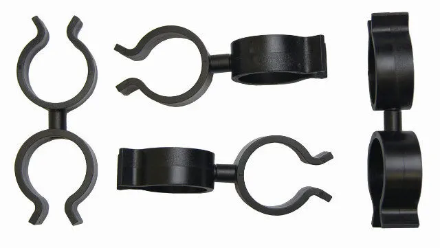
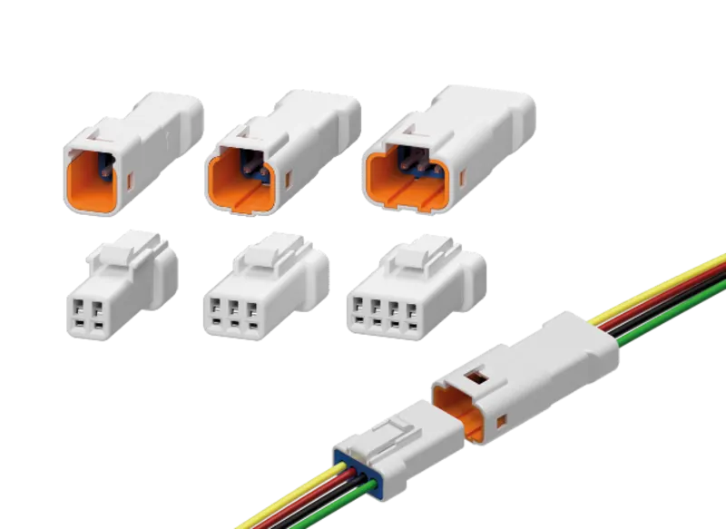
BACKSHELL: These are the extra protecting parts for the bundle and connectors. These are not exactly required. There will be only one entry and one exit point.
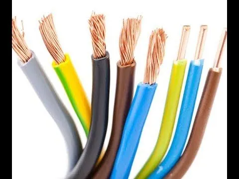
CORRUGATED TUBES & INSULATION TAPES: These are protective covering for bundles. The color of the COT tubes defines the electrical component as specified by the customer.
ASSIGN ELECTRICAL PROPERTIES

CLIP:

1) Download the required part file from the te.com

2) In the part design create points and planes at the entry, exit and base.

3) Switch to Electrical part design, Select the DEFINE SUPPORT PART

4) Give the entry point and plane as first plane, exit as second plane and base as third plane.

5) Repeat the step 3 and 4, this time give opposite end as entry.

6) Clip electrical properties are assigned.
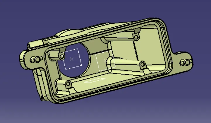
BACK SHELL:

1) Download the back shell from te.com

2) Create point and axis at the bundle entry point (where connector comes into contact).

Y-axis: In the direction of bundle

X and Z – any direction.

3) Switch to Electrical part design. Click on DEFINE BACKSHELL. Select the part body, keep the type as uncut.

4) Now click on DEFINE BACKSHELL CONNECTION POINT. Give the representation as centre point, Coincidence as Y-axis and Orientation as X/Z axis.

5) Electrical properties to back shell are assigned.
CORRUGATED TUBES & INSULATION TAPES:

1) Create a new part in electrical part design.

2) Select DEFINE PROTECTION PART

3) select the axis system.

4) Give the inner diameter, outer diameter and save the cot tube in separate catalogue created for corrugated tubes and insulation tapes.

5) Repeat the same steps for creating all corrugated tubes

6) Repeat the same procedure but this time select tapes in the protective part type and save the part in tapes catalogue.

7) Electrical properties are assigned to corrugated tubes and insulation tapes.

SOLUTION METHODOLOGY:

1. P - CLAMP:

  • P-Clamp is an Electrical Support equipment which provides support to the wire bundle to remain fixed to the automobile or any components or parts.The wire bundle can enter and exit from any side as it is a bi-directional equipment.So, we need to specify the Entry and Exit points from both the sides.To define the P-Clamp as Electrical Support equipment we need to follow the below steps:

Step - 1:

  • First download the CAD part and open it using the CATIA V5 software.

Step - 2:

  • Now we have to define the geometry parameters.
  • In order to define the geometry parameters, we need to navigate to the Part Workbench.
  • Then we need to create points and plains at the entry and exit points.

Step - 3:

  • Now in order to define the P-Clamp as a Electrical support we have to navigate to the Electrical Part design Workbench.
  • Now using the 'Define support part' option we can define the P-Clamp Entry and Exit points.
  • As the P-Clamp is Bi-directional so we need to define the support two times.

TREE STRUCTURE:

2. BACKSHELL

  • A backshell is an accessory that mounts to the rear threads of a connector to enhance its operational characteristics. The primary function of a backshell is to provide strain relief, which minimizes stress from the cable, on the junction where the wires terminate to the contacts.
  • Backshells come in a variety of finishes, materials, and angle configurations. For material compatibility and aesthetics, backshells and connectors should have a matching material and finish. And to provide simple cable management, most backshells may be ordered in 45º and 90º angles.
  • To define the Electrical properties of the backshell we need to follow the below steps:

Step - 1:

  • First download the 3-D CAD part of the backshell and open it using the CATIA V5 software.

Step - 2:

  • Identify from which side the bundle will enter and the side which will mate with the connector.

Bundle Entry Side:

Connector mating side:

Step - 3:

  • Create mid-point at the bundle entry side.
  • Create mid-point at the connector mating side.

Bundle entry side:

Connector mating side:

Step - 4:

  • Create an Axis system at the Connector mating side.
  • The axis system should be created at the center of the mating surface.
  • The axis must be defined as defined for the connectors show that it will connect easily.
    • Y- axis: Normal to the mating surface
    • X-axis: Normal to the locking side

Step - 5:

  • To define the Electrical properties, we need to navigate to the Electrical Part design workbench.
  • There we need to define the component as the 'Backshell'.

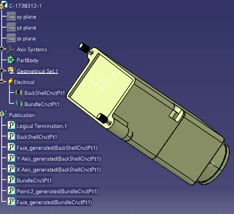
Step - 6:

  • Define the Backshell connection point.
  • Then define the Bundle connection point.

Backshell Connection Point:

Bundle Connection Point:

TREE STRUCTURE:

3. CORRUGATED TUBES:

  • Corrugated Tubes are used as protection coverings for the wire bundle from any type of damages.
  • Create a Catalogue document and adding Slit COT as a family and saving the document in our desired folder.
  • Creating the following corrugated tubes as per the dimensions given in the table and storing in the Slit COT family catalogue document.

Name

ID (mm)

OD (mm)

Thickness (mm)

15mm COT

12

15

1.5

20mm COT

17

20

1.5

35mm COT

32

35

1.5

10mm COT

7

10

1.5

5mm COT

3

5

1

1. 15 mm COT TUBE:

2. 20 mm COT TUBE:

3. 35 mm COT TUBE:

4. 10 mm COT TUBE:

5. 5 mm COT TUBE:

CORRUGATED TUBE CATALOGUE:

CONCLUSION:

  • From the above assignment we learnt how to define the Electrical support for a P-Clamp and also define its Electrical properties.
  • We also learnt how to Electrical Backshell for a Backshell component and also define its Electrical properties.
  • We also learnt how to make Corrugated Tubes of different diameters and also save them in the respective families in the Corrugated Tubes catalogues.
  • The required clips, backshells, corrugated tubes, and insulation tapes are defined electrically in CATIA V5 and are stored in the respective catalogs
Your portfolio, next

Ship work like this
in your own course.

Talk to a career counsellor

Free 20-minute call. We'll map the right course to where you want to work.

By submitting you agree to our Terms and Privacy Policy.