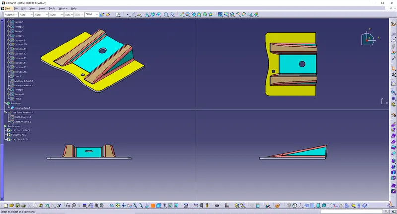
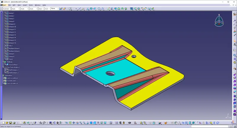
Week 8 - Challenge 1 - Base Bracket Design
Aim :
Create the Base Bracket Plastic component through the given Class-A surface. To begin with, the tooling axis for the given Class-A Surface should be created meeting the requirements of the draft angle and at the end perform the Draft analysis on the model.
Tooling Axis:
The dummy tooling axis is created to creat the main tooling axis.Take the intersection of the bracket body and make the lines in the deficult area in the bracket.Then Bisect the lines to create the tooling axis.
Class A surface:
It is the visible aesthetic surface which have curvature and tangency alignment to ideal aesthetical reflection quality of any automotive component. Class A surface refers to those surfaces which are visible It is a required where aesthetics has a significant contribution.
Class B surface:
It is a surface which is offset below a certain thickness from the class A surface. All the features of the product are to be performed on the class B surface with respect to class A surface
Class C surface:
class c surface is the surface which is used to join both the Class A and Class B. This surface connects both A and B surfaces along the Tooling Axis. It contains the draft as per the design. It is basically the thickened surface between both A and B surface
DRAFTING:
When developing parts for plastic injection molding, applying draft (or a taper) to the faces of the part is critical to improving the moldability of your part. Without it, parts run the risk of poor cosmetic finishes, and may bend, break, or warp due to molding stresses caused by the plastic cooling. Equally important, an absence of draft may prevent parts from ejecting from the mold, damaging not only the parts, but possibly the mold itself—a costly and time-consuming detour.
DRAFTING ANALYSIS:
The Draft Analysis command enables you to detect if the part you drafted will be easily removed. This type of analysis is performed based on color ranges identifying zones on the analyzed element where the deviation from the draft direction at any point, corresponds to specified values.
PROCEDURE:
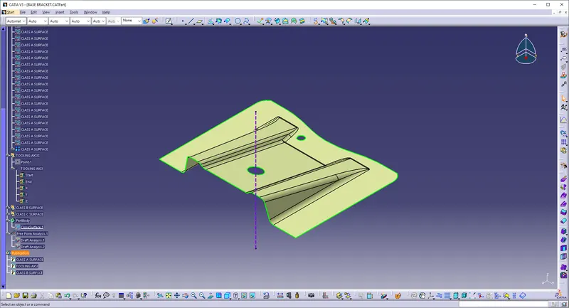
Selecting z axis as our tool axis we get the following :
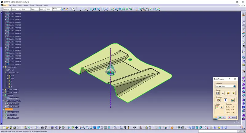
Creating the dummy tool axis we get the following :
Taking the intersection we get the following :
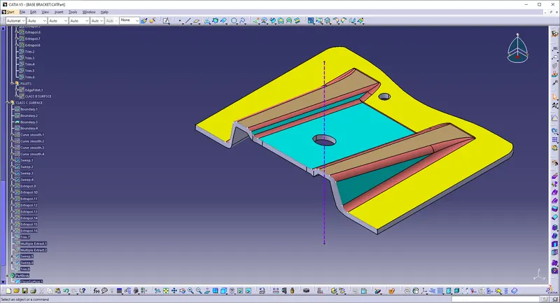
After using draft analysis we get the following :
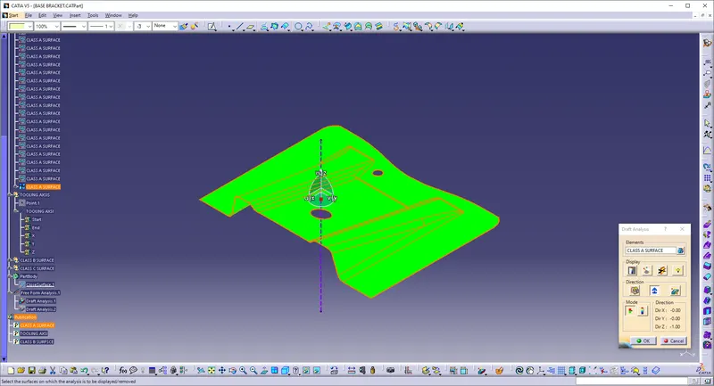
As you can see the draft analysis shows that the draft at certain areas is 43 -15 degrees which is more than the required draft degree.
Creation of Class B surface :
1.Creation of Ribs we get :
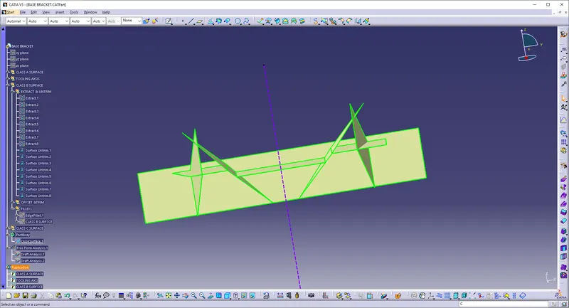
Using the extract command with no propagation we get the following :
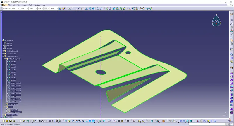
Using the untrim commamd we get :
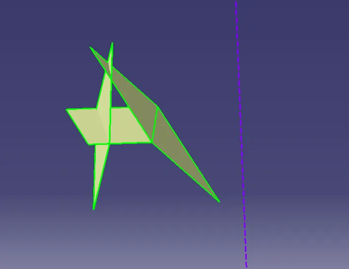
Using the untrim command we get the following :
After the trimming we get :
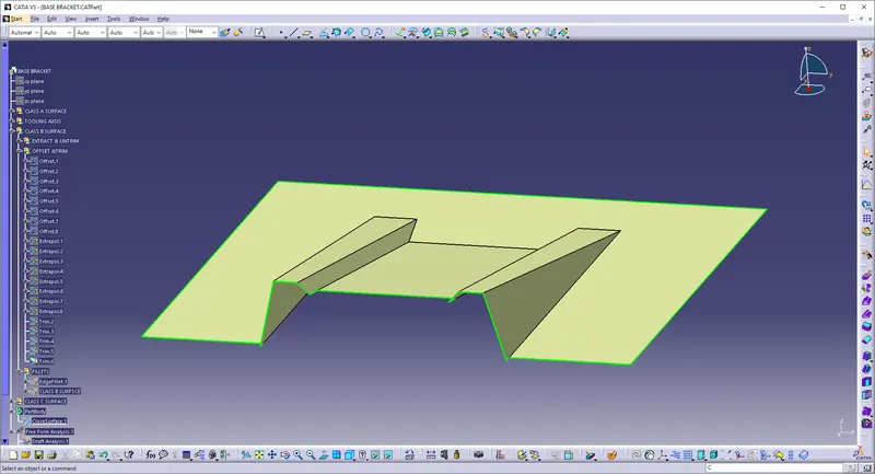
In the same manner we have created rib 2 using the above procedure.
Creation of Base Surface :
Now we have extracted the base surface from the class A surface and after that used untrim command as shown below :
After this we have used extrapolate and extract surfaces and got more surfaces from the Class A surface as shown below :
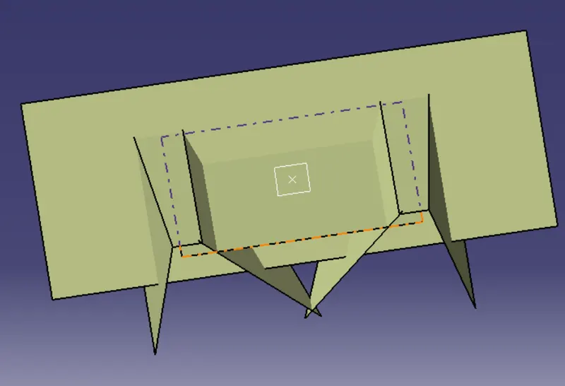
Now we will use trim to get the following as shown below :
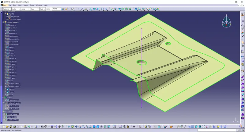
After this we add the fillet which is the sum of thickness of the component and the fillet value :
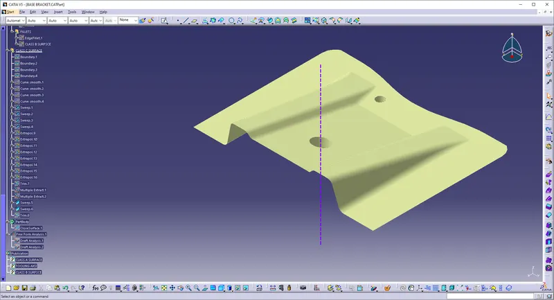
Creation of C Surface :
We have created boundary surface as shown below :
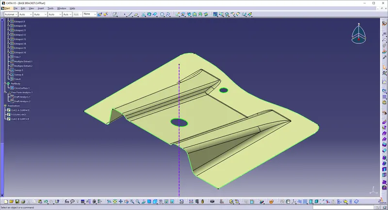
After giving draft we get the following :
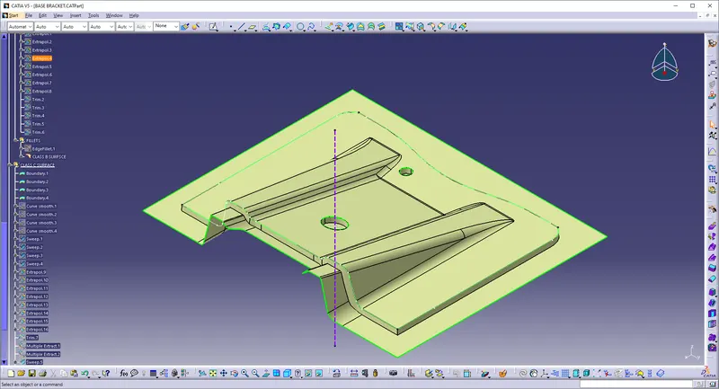
After using commands such as trim ,join and sweep we have created the following body using close surface :