Wiring harness routing & packaging Rules Week 3 Challenge
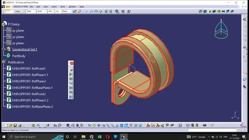
The P-clip acts as a support part for the wire bundle. Here in electrical part design workbench it is defined as a support part. It has one entry and exit point.
The direction of entry and exit can be either of the two points.
Firstly the geometrical set is defined.
Then the part is defined as support part. There after, bundle entry pont, exit point and bundle base is also defined. Now the part can be used for further assembly.
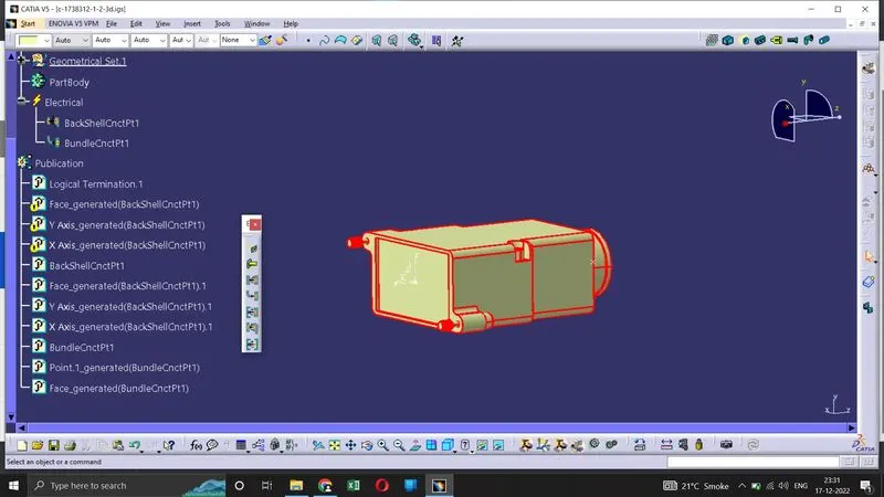
Backshells are also support part. These are plastic moulded part used at the wire entry side of the connectors. Including a backshell is not mandatory.
Backshells are defined as electrical part in the following way :
1. Geometrical sets is defined on the part
2. Backshell is defined, and at this stage we can also give extra length.
3. Backshell connection point is defined
4. Bundle connection point is defined.
On the connector, it is also necessary to define the backshell connection point in order to assemble it to the mating backshell.
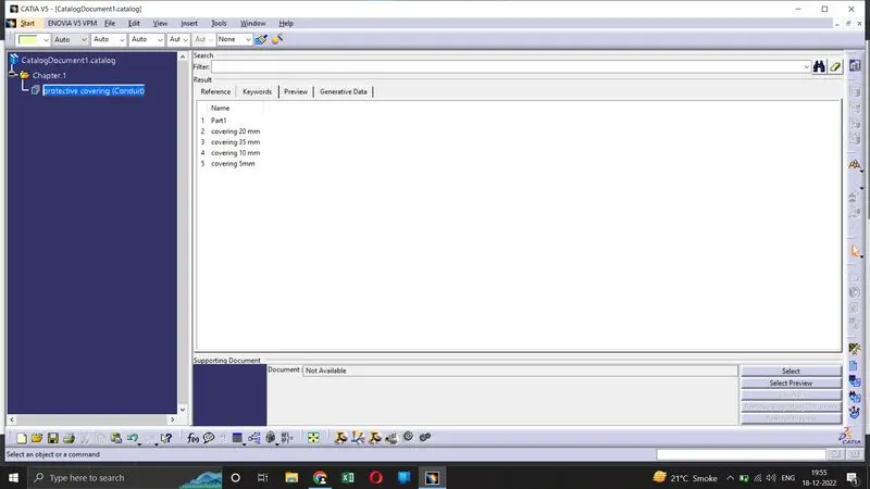
Next, we create protective covering. We need to create visual representation in catia using the command "protective covering" in the Electrical design workbench.
First, select the part body. Then add the desired dimensions of the protective tube.
We need to give inner and outer diameter dimensions as well as bend radius. The bend radius followed is usually 1.5 times the OD.
After the part is created, it is added to required catlogue family for future use.