Wiring harness routing & packaging Rules Week 3 Challenge
REPORT
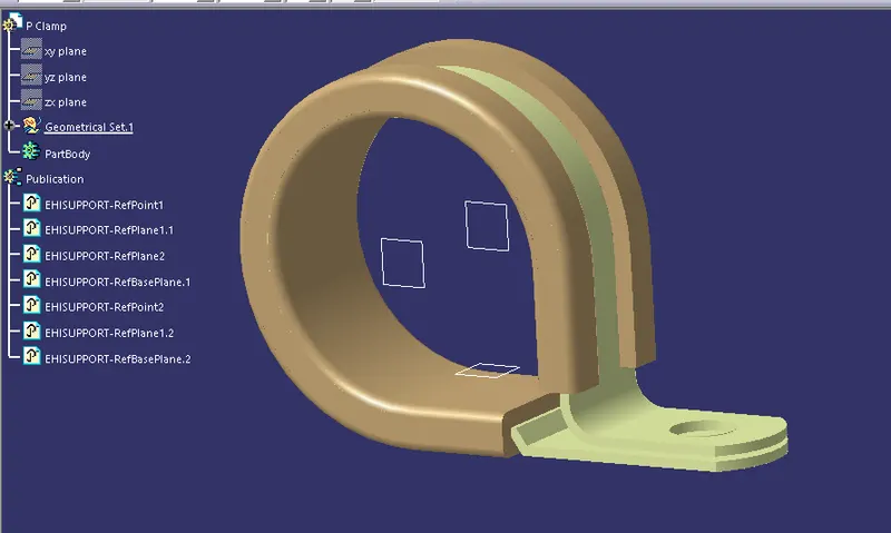
Defining P Clamp.
The following steps are being followed:
- The given CAD file is downloaded and opened in CATIAV5 Software
- While defining the P Clamp, 2 entry sides and a base should be given
- Using part design workbench the points at the 2 sides are created using centre of circle definition
- Planes parallel to their respective sides are created at these point as reference
- And a base plane is being created as shown in below Snip
- Now the part is being defined as Support part using Define Support Part workbench in Electrical part design workbench
- The inputs are given as First Point and Plane, Second Point and Plane and a Base Plane
- This process is repeated once again as we need to consider both side entry provision
- But this time we need to select the First point which is selected as second point previously
- The second point will be selected by default, which was the first point in earlier case
- And also the base plane is selected and Say ok
- Finally Saving the Part, and also in the Standard Catalogue using Store Device Tool
- This Completes the Process
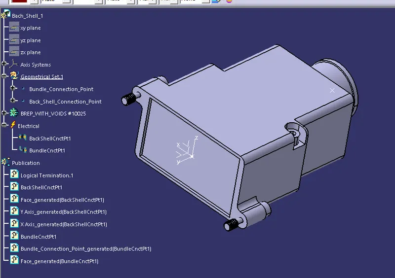
Defining Back Shell.
The following steps are being followed:
- The Given CAD Files is being downloaded and Renamed as Back_Shell_1
- The given back shell was straight type,
- It should have 1 bundle entry point and one Back shell connection point
- The two points as above using part workbench in CATIAV5 Software is being created
- The axis system for the same is also being created
- Now the part is electrically defined as Back shell using define back shell tool in Electrical part design workbench
- Now the Bundle connection Point and Back Shell Connection Point is Defined respectively
- For Back shell Connection Point Face is given as Contact reference, X axis as Orientation and Y axis as direction of Coincidence
- Finally Saving the Part, and also in the Standard Catalogue using Store Device Tool
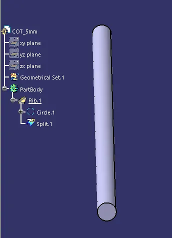
Creation of COT Tubes.
The following steps are being followed:
- The new part file is opened,
- In Electrical Part design workbench, Used Define Protection Part tool
- Now clicking on Part name it pops up a tab
- The data are filled that includes Inner Diameter, Thickness and Bend Radius
- Bend Radius will be generally around 1.5 times the outer diameter
- Save the name as COT_X mm
- Save the part
- Here entry points or planes are not necessary
- Store it in new catalogue named as “SlitCOT”
- Similarly created all other 4 Cot Tubes and being stored in the same catalogue