Wiring harness routing & packaging Rules Week 3 Challenge
1. Defining Hellarmann Tyton – 21160129
- The clip data is downloaded from 'Hellermann Tyton's' official website
In Part Design workbench
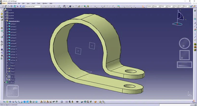
- Three planes are made such that
- One plane is on the side of the clip with a point in the center of the curve and the reference plane as the face normal to wire-entry/exit
- Second plane on the opposite side of the clip with a point in the center of the curve and the reference plane as the face normal to wire-entry/exit
- Third plane at 2mm from the bottom inner plane
In Electrical Part Design workbench
- Click on the 'Support Part' icon and then click on the part
- Then the support is defined with:
- Name: Hellarmann Tyton – 21160129
- First Plane definition
- Point: Point.1 (The point made on the plane for the wire entry/exit)
- Plane: Plane.1 (The corresponding plane for the chosen point)
- Second Plane Definition
- Plane: Plane.2 (The plane opposite to the chosen first plane)
- Third Plane Definition
- Plane: Plane.3 (The base plane)
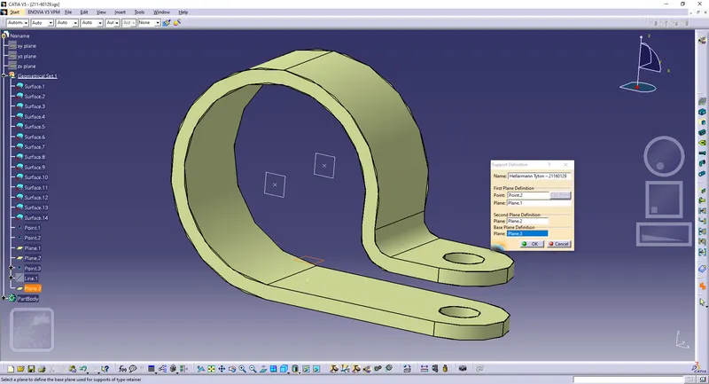
- The support is defined again for the other side by clicking on the 'Support Part' icon and then clicking on the part
- Then the support is defined with:
- Name: Hellarmann Tyton – 21160129
- First Plane definition
- Point: Point.2 (The point made on the opposite plane for the wire entry/exit)
- Plane: Plane.2 (The corresponding plane for the chosen point)
- Second Plane Definition
- Plane: Plane.2 (This plane is already chosen by default because of our previous definition)
- Third Plane Definition
- Plane: Plane.3 (The base plane is also already chosen by default because of our previous definition)
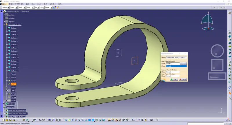
For Catalog Entry
- Click on 'store device' on the electrical part design workbench and choose the catalog and their respective family
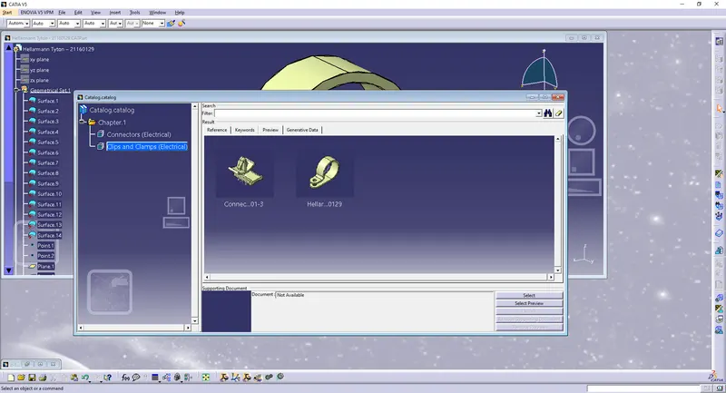
2. Defining Tyco 1738312-1
- The Backshell is downloaded from the given link
In Part Design Work Bench:
- The Backshell Connection Point and the Bundle Entry Point are defined on their respective mating faces
- The required axis system is defined for the Backshell Connection Point
- Then the Work Bench is changed to 'Electrical Part Design'
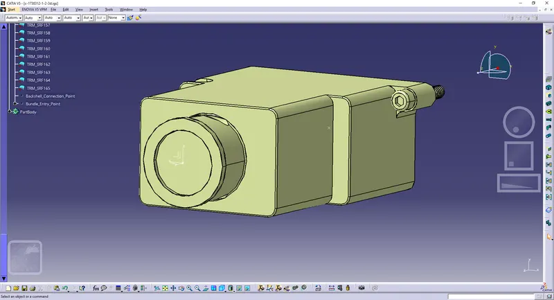
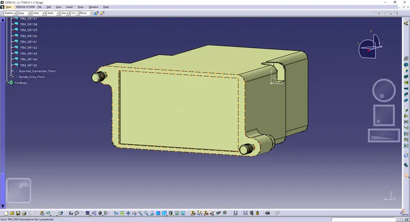
In Electrical Part Design Work Bench:
- The 'Define Backshell' icon is selected and the part is selected and the Backshell is defined as:
- Part Number: C-1738312-1
- Extra Length: Unset
- Then the Backshell Connection Point is defined with
- Representation: Backshell_Connection_Point
- Contact: Mating Face
- Coincidence: Y-Axis
- Orientation: X-Axis
- Then the Bundle Entry Point is defined with
- Representation: Mating Face
- Point: Bundle_Entry_Point
- Initial Condition: Mating Face
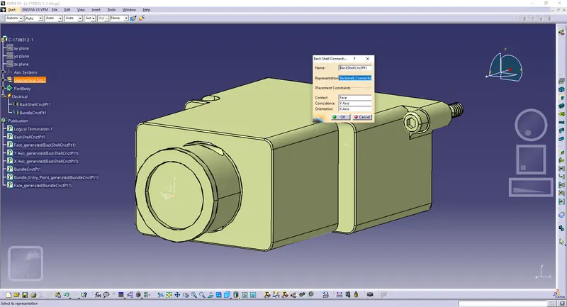
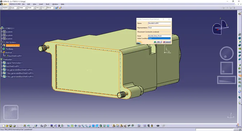
For Catalog Entry
- Click on 'store device' on the electrical part design workbench and choose the catalog and their respective family
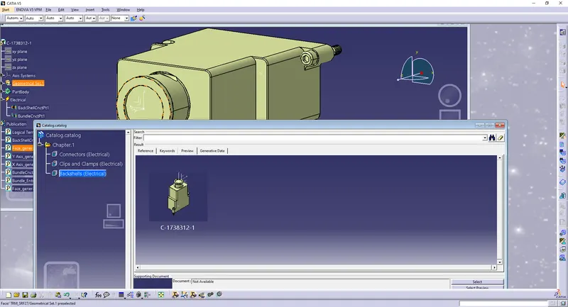
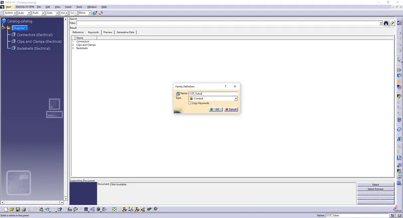
3. Creating Corrugated Tubes and their Catalogue:
Creation of 15mm COT tube with 1.5mm thickness:
- Click on File>New>Part
- Name: COT_15mm and click on OK
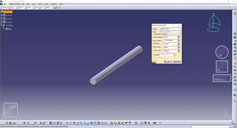
- Click on the 'Define Protection Part' icon
- Click on the part name in the feature tree
- Define Protection Part:
- Name: COT_15mm
- Type: Corrugated tube
- Parameter definition
- Inner Diameter: 12mm
- Inner Section: Automatically Calculated
- Thickness: 1.5mm
- Bend Radius: 18mm (1.5 times the inner diameter)
- Linear mass: default
- Line type: 1
- Light geometry: enabled
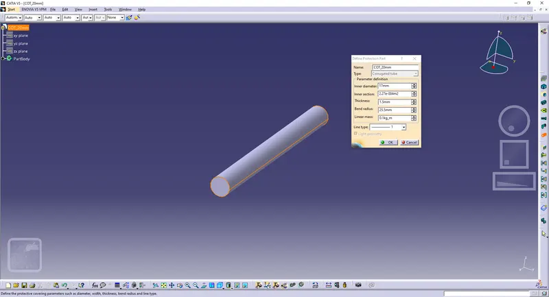
Creation of 20mm COT tube with 1.5mm thickness:
- Click on File>New>Part
- Name: COT_20mm and click on OK
- Click on the 'Define Protection Part' icon
- Click on the part name in the feature tree
- Define Protection Part:
- Name: COT_20mm
- Type: Corrugated tube
- Parameter definition
- Inner Diameter: 17mm
- Inner Section: Automatically Calculated
- Thickness: 1.5mm
- Bend Radius: 25.5mm (1.5 times the inner diameter)
- Linear mass: default
- Line type: 1
- Light geometry: enabled
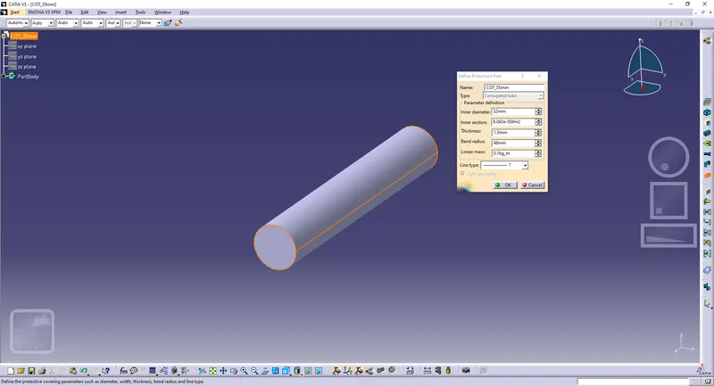
Creation of 35mm COT tube with 1.5mm thickness:
- Click on File>New>Part
- Name: COT_35mm and click on OK
- Click on the 'Define Protection Part' icon
- Click on the part name in the feature tree
- Define Protection Part:
- Name: COT_35mm
- Type: Corrugated tube
- Parameter definition
- Inner Diameter: 32mm
- Inner Section: Automatically Calculated
- Thickness: 1.5mm
- Bend Radius: 48mm (1.5 times the inner diameter)
- Linear mass: default
- Line type: 1
- Light geometry: enabled
Creation of 10mm COT tube with 1.5mm thickness:
- Click on File>New>Part
- Name: COT_10mm and click on OK
- Click on the 'Define Protection Part' icon
- Click on the part name in the feature tree
- Define Protection Part:
- Name: COT_10mm
- Type: Corrugated tube
- Parameter definition
- Inner Diameter: 7mm
- Inner Section: Automatically Calculated
- Thickness: 1.5mm
- Bend Radius: 10.5mm (1.5 times the inner diameter)
- Linear mass: default
- Line type: 1
- Light geometry: enabled

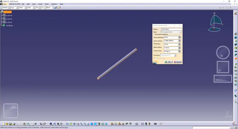
Creation of 5mm COT tube with 1mm thickness:
- Click on File>New>Part
- Name: COT_5mm and click on OK
- Click on the 'Define Protection Part' icon
- Click on the part name in the feature tree
- Define Protection Part:
- Name: COT_5mm
- Type: Corrugated tube
- Parameter definition
- Inner Diameter: 3mm
- Inner Section: Automatically Calculated
- Thickness: 1mm
- Bend Radius: 7.5mm (1.5 times the inner diameter)
- Linear mass: default
- Line type: 1
- Light geometry: enabled