Wiring harness design in CATIA V5 - 3D modeling Week 2 Challlenge
1.Defining Deutsch DT06 – 08SA:
- The connector is downloaded from the given link
In Part Design Work Bench:
- The Connector Connection Point and the Bundle Entry Point is defined on the mating face
- The required axis system is defined for the connector connection point
- Then the Work Bench is changed to 'Electrical Part Design'
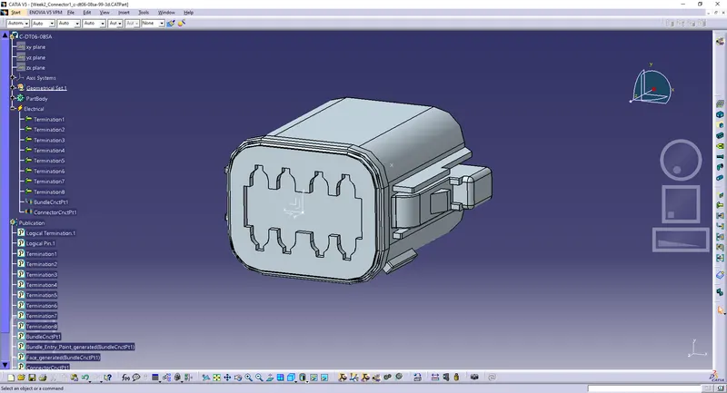
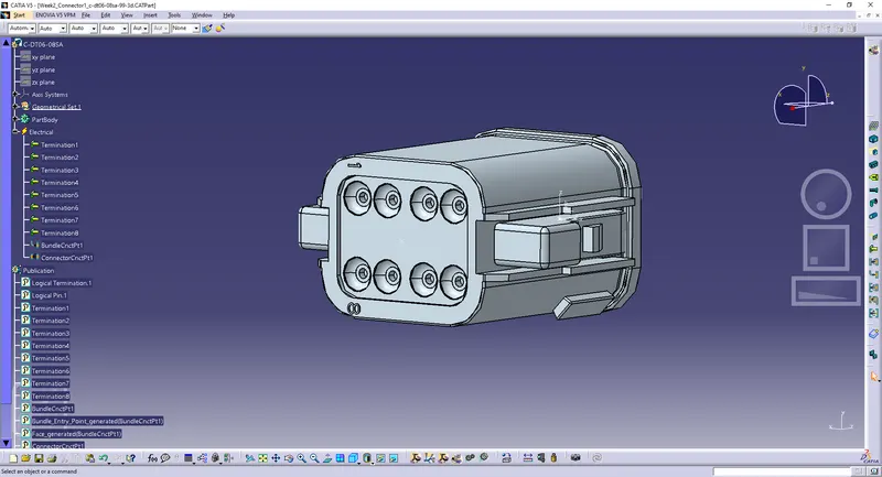
In Electrical Part Design Work Bench:
- The connector is defined as a connector
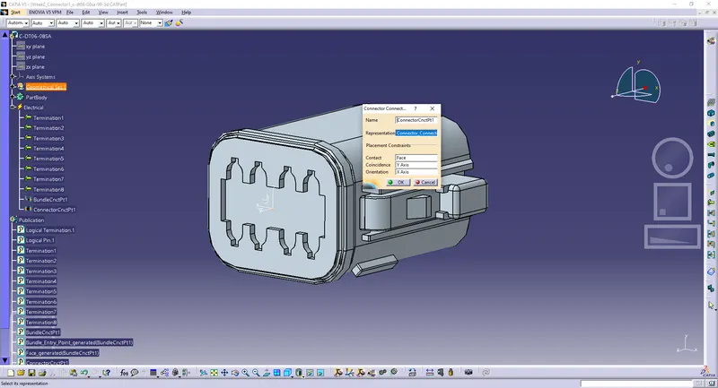
- Then the connector connection point is defined with
- Representation: Connector_Connection_Point
- Contact: Mating Face
- Coincidence: Y-Axis
- Orientation: X-Axis
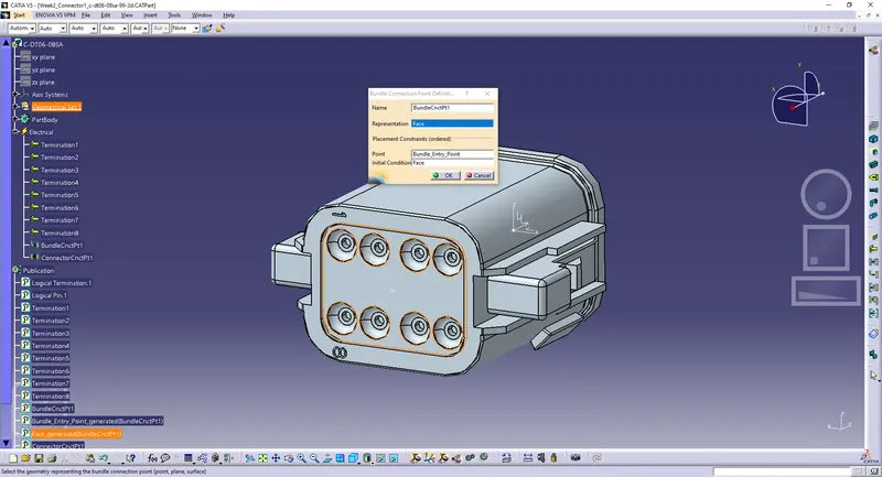
- Then the Bundle Entry Point is defined with
- Representation: Mating Face
- Point: Bundle_Entry_Point
- Initial Condition: Mating Face
2. Defining Tyco 174357-2:
- The connector is downloaded from the given link
In Part Design Work Bench:
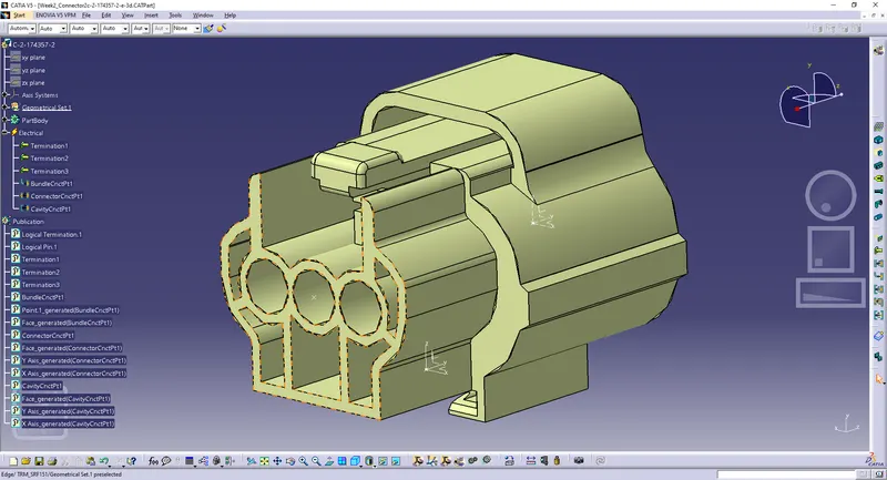
- The Connector Connection Point and the Bundle Entry Point is defined on the mating face
- The required axis system is defined for the connector connection point
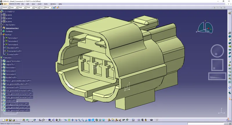
- The Cavity Connection Point is defined on its respective mating face
- The required axis system is defined for the Cavity Connection Point such that it matches the one defined for the Connector Connection Point
- Then the Work Bench is changed to 'Electrical Part Design'
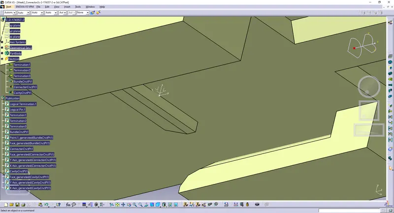
In Electrical Part Design Work Bench:
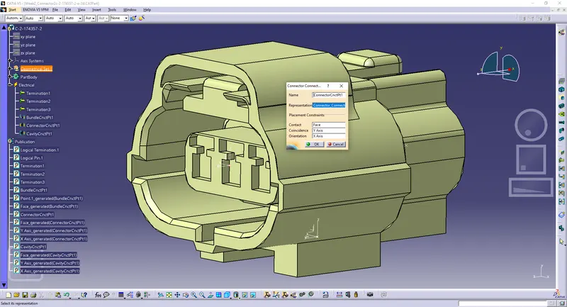
- The connector is defined as a connector
- The connector connection point is defined with
- Representation: Connector_Connection_Point
- Contact: Mating Face
- Coincidence: Y-Axis
- Orientation: X-Axis
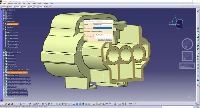
- The Bundle Entry Point is defined with
- Representation: Mating Face
- Point: Bundle_Entry_Point
- Initial Condition: Mating Face
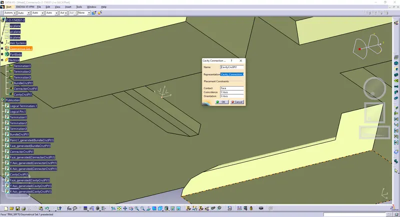
- The Cavity Connection Point is defined with
- Representation: Cavity_Connection_Point
- Contact: Mating Face
- Coincidence: Y-Axis
- Orientation: X-Axis
3. Defining Tyco 85229-1:
- The connector clip is downloaded from the given link
In Part Design Work Bench:
- The Cavity Connection Point is defined on its respective mating face
- The required axis system is defined for the Cavity Connection Point such that it matches the one defined for its respective connector
- Then the Work Bench is changed to 'Electrical Part Design'
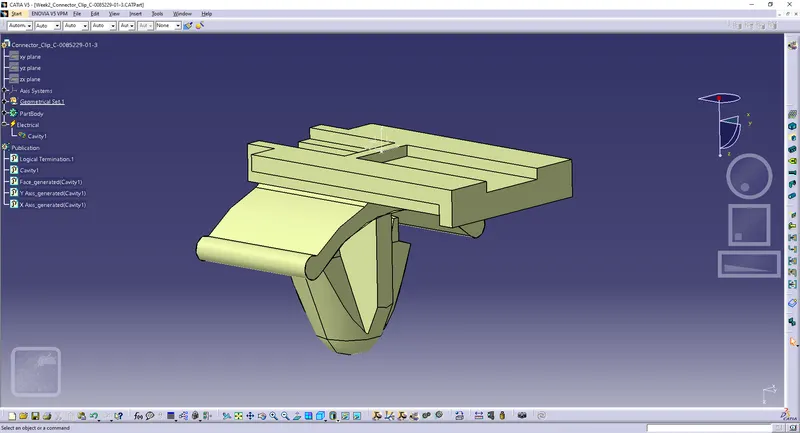
In Electrical Part Design Work Bench:
- The connector clip is defined as a 'Mounting Equipment'
- Then the part is defined as cavity with
- Representation: Point.1
- Contact: Mating Face
- Coincidence: Y-Axis
- Orientation: X-Axis
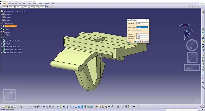
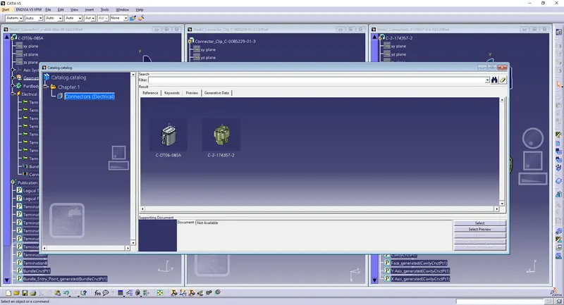
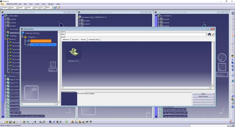
Creating a Catalogue and adding these models to them:
- Click on File>New>Catalog Document>Ok
- Click on Add Family icon
- Name: Connectors
- Type: Electrical
- Click on Add Family icon
- Name: Clips and Clamps
- Type: Electrical
- Click on File>Save>Enter Catalog Name>Save
- Go to each connector and clip and click on 'store device' on the electrical part design workbench and choose the catalog and their respective family